HME Clear-Com FreeSpeak Edge User manual

User Guide
FreeSpeak Edge™ Base Station
User Guide
Part Number: PUB-00113 Revision A
June 24, 2021

Document reference
FreeSpeak Edge Base Station User Guide
Part Number: PUB-00113 Revision A
Legal disclaimers
Copyright © 2021 HME Clear-Com Ltd
All rights reserved
Clear-Com, the Clear-Com logo, and Clear-Com Concert are trademarks or registered
trademarks of HM Electronics, Inc.
The software described in this document is furnished under a license agreement and may be used
only in accordance with the terms of the agreement.
The product described in this document is distributed under licenses restricting its use, copying,
distribution, and decompilation / reverse engineering. No part of this document may be
reproduced in any form by any means without prior written authorization of Clear-Com, an HME
Company.
Clear-Com Offices are located in California, USA; Cambridge, UK; Dubai, UAE; Montreal,
Canada; and Beijing, China. Specific addresses and contact information can be found on Clear-
Com’s corporate website: www.clearcom.com
Clear-Com contacts:
Americas and Asia-Pacific Headquarters
California, United States
Tel: +1 510 337 6600
Email: [email protected]
Europe, Middle East, and Africa Headquarters
Cambridge, United Kingdom
Tel: +44 1223 815000
Email: [email protected]
China Office
Beijing Representative Office
Beijing, P.R. China
Tel: +8610 59000198/59002608
Email: [email protected]
Page 2

Table of contents
1 Introduction 6
1.1 Product Features 7
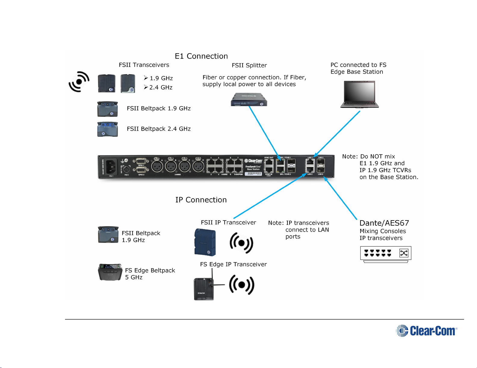
1.2 FreeSpeak Edge Base Station Interconnections 8
2 Installing FreeSpeak Edge Base Station 9
2.1 Front Panel Connectors, Controls and Indicators 10
2.2 Intercom Touchscreens 12
2.3 Rear Panel Connectors and Indicators 14
2.4 System Powering 15
2.5 Clear-Com Ethernet Cable Recommendations 16
2.6 Stage Announce and Program Feed 17
2.7 Setting the Management IP Address 17
2.8 Saving and Restoring System Configuration 20
2.9 Resetting to Default 21
3 Core Configuration Manager (CCM) Walkthrough 22
3.1 Accessing the CCM 24
3.2 Changing the CCM Password 25
3.3 Hardware Page Overview 26
3.4 Configuration Page Overview 27
3.5 Status Page 31
4 Example Applications 32
4.1 Fast and Easy Setup: E1 33
4.2 Using E1 With Six Transceivers 35
4.3 Using IP Transceivers with the Base Station 37
4.4 Split Frequency Setup (5, 2.4 and 1.9 GHz System) 39
5 Connecting Transceivers 40
5.1 Overview of Transceivers 41
5.2 Connecting Transceivers Over E1 42
5.3 Connecting Transceivers Over IP 46
6 Network Setup 47
6.1 Network Setup for IP Transceivers 48
6.2 FreeSpeak Edge Base Station LAN Configuration Rules 53
7 Connecting to other systems 54
7.1 Connecting 2-Wire Systems 55
Page 3

7.2 Connecting 4-Wire Systems 58
7.3 Connecting to Dante-Enabled Devices 62
8 Configuring from the CCM 65
8.1 Configuring Station Settings 66
8.2 Adding IP Transceivers (FS Edge, FS II 1.9) 71
8.3 Registering Beltpacks 72
8.4 Channels and Groups 74
8.5 Managing Channels 76
8.6 Managing Groups 80
8.7 Creating and Editing Roles 86
8.8 Setting up GPIOs and Logic Events 91
8.9 Monitoring System Status 94
9 Security 101
9.1 Warning 102
9.2 Introduction 102
9.3 Using Security Certificates 103
9.4 Forcing HTTPS 104
10 Configuring from the Front Panel 106
10.1 Introduction to Configuring from the Front Panel 107
10.2 Front Panel Menus 108
10.3 Passwords, Addresses and Reset to Default Settings 112
11 Upgrading 114
11.1 Introduction 115
11.2 Upgrading using the CCM 115
11.3 Upgrading using a USB stick 115
12 Spare parts 117
13 Front Panel Menu Reference Tables 118
13.1 Audio Settings 119
13.2 Host Settings 119
13.3 2 W Audio (A/B) (C/D) 120
13.4 Discovery 120
13.5 Transceiver 121
13.6 Networking 122
13.7 Administration 123
14 Specifications 125
Page 4

14.1 FreeSpeak Edge Base 126
14.2 Capacity 129
14.3 Frequency Response - Base to Beltpack 129
14.4 Front Panel Headset Microphone 130
14.5 Network Specifications 131
15 Pinouts 133
15.1 GPIO pinouts 134
15.2 2-Wire Pinouts 135
15.3 4-Wire Pinouts 136
15.4 DECT Sync 136
16 Regulatory Compliance 137
16.1 FCC Notice 137
16.2 FCC/IC/EC RF Exposure Warning 138
16.3 Industry Canada Compliance Statement 138
16.4 Korean Notice 138
16.5 European Union (CE mark) 139
16.6 United Kingdom (UKCA Mark) 139
16.7 Electrical and Electronic Equipment (WEEE) Waste 140
Page 5

User Guide | FreeSpeak Edge Base Station
1.1 Product Features
FreeSpeak Edge Base Station is a low-latency intercom platform that interconnects with wired
and wireless intercom systems.
FreeSpeak Edge Base Station supports:
lSix IP transceivers (any combination up to a total of six of FreeSpeak II and FreeSpeak
Edge TCVRs)
l10 E1 transceivers (any combination up to a total of 10 of FreeSpeak II 1.9 and 2.4
TCVRs)
l16 wireless beltpacks (any combination up to a total of 16 of FreeSpeak II and FreeSpeak
Edge beltpacks
lEight Dante channels
lEight 4-wire ports
lPort 8 is dedicated to program feed and stage announce
lFour 2-wire ports (Clear-Com or RTS)
The secure browser-based Core Configuration Manager (CCM) offers intuitive configuration
and you also have the option of using the touch-sensitive front-panel screens.
You can connect the FreeSpeak Edge Base Station to:
lWireless transceivers:
l1.9 GHz - E1 or IP connection
l2.4 GHz - E1 only
l5 GHz - IP only
l2-wire and digital partyline systems such and Encore
lDante compliant systems
System limits:
l100 channels
l100 groups
l200 roles
Page 7

User Guide | FreeSpeak Edge Base Station
1.2 FreeSpeak Edge Base Station Interconnections
The following graphic shows an overview of how the FreeSpeak Edge Base Station can interconnect with other intercom components.
Page 8

User Guide | FreeSpeak Edge Base Station
2 Installing FreeSpeak Edge Base Station
This chapter describes the front and rear panels, power supplies and cabling recommendations.
It also describes network setup and illustrates example applications. It contains the following
sections:
2.1 Front Panel Connectors, Controls and Indicators 10
2.2 Intercom Touchscreens 12
2.3 Rear Panel Connectors and Indicators 14
2.4 System Powering 15
2.5 Clear-Com Ethernet Cable Recommendations 16
2.6 Stage Announce and Program Feed 17
2.7 Setting the Management IP Address 17
2.8 Saving and Restoring System Configuration 20
2.9 Resetting to Default 21
Page 9

User Guide | FreeSpeak Edge Base Station
2.1 Front Panel Connectors, Controls and Indicators
Page 10

User Guide | FreeSpeak Edge Base Station
The FreeSpeak Edge front panel connectors, controls and indicators are listed below.
Item Description
A Headset connector (4-pin XLR female)
BMicrophone key
Menu key
CRotary Controllers. Use these to control channel volume, mute or unmute
audio, or to navigate through the menu system.
D Main Volume Control
E
Main Volume Level LEDs:
lRed - high volume level
lAmber - medium volume level
lGreen - low volume level
F
Base Station status LED
lOff - the device is off or initializing.
lOn (solid green) - All ok with the device.
lFlashing green (slow, 2 Hz) - there are warning(s) with the device.
lFlashing green (fast, 4 Hz) - there are error(s) with the device.
G Color touchscreen displays
H Pin reset
I Power Input LEDs
J
USB A connector.
Use to:
lRegister beltpacks
lUpgrade the Base Station
lSave/Restore system settings
lObtain detailed logs for diagnostic purposes
Page 11

User Guide | FreeSpeak Edge Base Station
2.2 Intercom Touchscreens
The Base Station has two intercom control touchscreens, available when the front panel
screens are not in menu mode. Each touchscreen provides access to two keys which can be
configured for channels, groups or point to point communications channels.
2.2.1 Left Intercom Touchscreen
Item Description
A Listen activation indicator.
BVolume level indicator. Control the volume with the rotary
controller next to the channel/audio source.
C Talk button.
D Call button. Use this to send a call signal.
E
Menu button. Touch to see:
lStage Announce
lAll talk
lRemote mic kill (RMK)
Page 12

User Guide | FreeSpeak Edge Base Station
2.2.2 Right Intercom Touchscreen
Item Description
AChannel indication. Audio routes can be point-to-point or
channels.
B
Notification bar
lBeltpack registration
lProgress of upgrades
lSupport information gathering
lResoration of configuration progress
CReply button. Use CLEAR to clear the currently visible
entry (does not clear the entire key stack).
Page 13

User Guide | FreeSpeak Edge Base Station
2.3 Rear Panel Connectors and Indicators
The rear connectors and indicators are listed below.
Item Description
A Internal power connector. Mains power lead with internal power supply.
B Grounding screw.
C
General Purpose Input/Output connectors x2 (DB-9F).
lGPIO 1 contains GPI1 and GPO1 & 2
lGPIO 2 contains GPI2 and GPO 3 & 4.
D XLR 2-wire Partyline connectors (standard microphone cable)
E
RJ45 4-wire audio and data connectors. Port 8 is dedicated to Program Feed (PGM)
and Stage Announce (SA), to be used with the split XLR cable connector that is
supplied with the Base Station.
F Dect Sync RJ45 connectors, IN, OUT.
G E1 RJ45 connectors to splitter/transceiver. Do not connect IP transceivers here.
H
SFP cage for E1 fiber connection to splitter/transceiver (Either single-mode or multi-
mode fiber modules. Modules must match existing cabling). Do not connect IP
transceivers here.
IRJ45 LAN connectors. IP transceivers, the configuration PC and Dante are
connected here. Capacity 1GB.
J SFP cage for fiber LAN connectors. Capacity 2.5 GB.
K SA/PGM
LExternal power supply connector (12V DC). CAUTION: Before using, see System
Powering on page 15.
Page 14

User Guide | FreeSpeak Edge Base Station
2.4 System Powering
There are two power supplies:
lMains power connector (IEC) internal power supply
lDC connector. External AC/DC power adapter
12V DC, 12A
Use one power connector, or both to guard against one failing.
2.4.1 Using the External DC Power Connector
CAUTION: YOU MUST CONNECT THE EXTERNAL DC POWER SUPPLY IN THE ORDER
DESCRIBED AND ILLUSTRATED BELOW:
1. Connect the external power
supply 12V cable connector (A) to
the rear chassis 12V input
connector of the Station.
Note: When connecting the power
cable, be sure to push until the
connector locks into the device.
2. Connect External Power Supply
mains cord (B) to the AC input
source.
Page 15

User Guide | FreeSpeak Edge Base Station
2.5 Clear-Com Ethernet Cable Recommendations
Cable recommendations
Category (Cat) Higher Cat numbers will support a higher
bandwidth. Therefore, by using a higher Cat
number you are future proofing your system
to some extent.Example:
lCat 5e : up to 1 GB
lCat 6: up to 10 GB
Use Cat 5e or higher.
American Wire Gauge (AWG) The lower the AWG number, the less
temperature rise there wil be in the cable
when using PoE. This is particularly important
for bundles. Local building regulations may
rule out the use of 26 AWG or higher,
depending on the installation. Check with your
local building regulations.Use AWG 24 or
lower.
Shielded Twisted Pair (STP) or Foiled
Twisted Pair (FTP)
Using shielded cable means less problems
with interference from other sources. This
means that your installation will be more
robust if you use shielded cables.
Note: Overall recommendation: Use Cat 6a, 23 AWG STP cable.
Page 16

User Guide | FreeSpeak Edge Base Station
2.6 Stage Announce and Program Feed
Your FreeSpeak Edge Base Station is supplied with an RJ45 connector that uses a splitter
cable to split into two XLR connectors. If you wish to use an external Stage Announce (SA) and
Program Feed (PGM), you must connect this to the RJ45 port labeled SA/PGM (port 8) on the
rear of your device, and connect your input (PGM) and output (SA) to these connectors.
Navigate to Configuration > Channels in the CCM and click the add button next to the
PGM and SA ports to put them into channels as required. These audio resources can be routed
to Channels,Groups,Roles and Logic events (GPIOs).
Note: These resource are unidirectional (simplex, not duplex).
2.7 Setting the Management IP Address
By default your Base Station works with DHCP IP addressing. However, you can set a static IP
address for any of the station IP ports (with the exception of Dante audio that is defined by the
Audinate Dante Controller).
The Management IP address can be set:
lFrom the Base Station front panel menus
lFrom the Core Configuration Manager (CCM)
Page 17

User Guide | FreeSpeak Edge Base Station
2.7.1 Setting the Management IP Address from the Front Panel Menus
1. Press the MENU button.
2. Using the far left rotary controller, navigate to Networking.
3. Select (Management.
4. Navigate to DHCP and select DISABLED. Push to select menu item.
5. A numerical touchscreen keypad appears in the screen.
6. Using the touchscreen, press Clr to clear the IP address field.
7. Enter the new IP address using the touchscreen.
8. Press OK.
9. Edit the subnet if required.
10. Press OK.
11. The Management IP address has been changed.
2.7.2 Setting the Management IP Address from the CCM
To access the CCM, see Core Configuration Manager (CCM) Walkthrough on page 22.
1. In the CCM, navigate to Hardware > Resources.
2. Click anywhere on the Base Station panel under Hosts.
3. In the Network tab, click Management.
4. Select Static.
5. Enter the required IP address and press the [Enter] key.
Page 18

User Guide | FreeSpeak Edge Base Station
2.8 Saving and Restoring System Configuration
Clear-Com recommends that you make a backup of your system configuration using the Save
option that is available in the CCM and the front panel menu system.
2.8.1 Saving System Configuration in the CCM
The Save and Restore options are available in the CCM top navigation bar.
When you click Save, all system configuration; channels, roles and network details are saved to
a file (.cca) on your computer.
2.8.2 Saving System Setup in the Front Panel Menus
1. Insert a USB drive into the USB connector on the front of the Base.
2. Press the Menu button.
3. Using the rotary controllers, navigate to Administration > Settings > Save.
4. Push the 4th rotary controller. System setting are saved to the USB drive. The progress of
this Save is shown in the notification bar on the front panel.
2.8.3 Restoring System Configuration
Your system configuration can be restored to the Base Station at any time using the Restore
button in the CCM and also from the front panel menu system.
On restore, the saved configuration is reapplied to the Base Station. The following aspects of
the configuration are optionally restored:
lNetwork settings (IP addresses)
lOver The Air system ID.
You do not get these options when restoring by USB directly to the Base Station. If you want to
restore system settings taken from different Stations, you must use the CCM Restore option, as
restoring directly from the Base Station in this situation would restore network and OTA system
ID and IP and could cause wireless ID conflicts.
Page 20
Other manuals for Clear-Com FreeSpeak Edge
1
Table of contents
Other HME Accessories manuals
Popular Accessories manuals by other brands

Campbell
Campbell SkyVUE Pro product manual

Intermec
Intermec RM91501X04 quick start guide

TOPPOINT
TOPPOINT LT91273 user manual

Benchmark Scientific
Benchmark Scientific Incu-Shaker Mini Operation manual

GOLDENSEA UV
GOLDENSEA UV UVT72 quick start guide

Balluff
Balluff BOD 26K Series Mounting and operating instructions