isobar fs mont uk / Senest udskrevet den 15-08-01 11:01 / MW.
English
Installation Guide IsoBar
2-65, 3-65, 2-70, 3-70, 2-72, 3-72, 4-60
This installation guide gives basic instructions which
are to be observed during installation, operation and
maintenance of the pump. It is therefore imperative
that this manual is read by the responsible
person/operator prior to the installation and should
always be kept available at the site.
It is not only the general safety instructions under this
main heading "Safety" that are to be observed but also
the specific information provided under the other main
headings.
Serial No: See nameplate
Application
The IsoBarcirculating pumps are used in all types
of heating systems. Via an internal speed Control, the
pump maintains predetermined differential heads at
varying flows (see control details under the heading
"Duty control"). This design concept gives electrical
and thermal savings together with reduced noise level
in the installation.
Pump medium
Clean, thin, nonaggressive and nonexplosive fluids
without any solids or fibres.
Antifreeze without any mineral oil (special model
available upon request).
Kinematic viscosity: Max. 10mm2/s
Please note: If any liquid other than water is being
pumped, were commend that you contact
T. Smedegaard A/S or their representative as the
pump characteristics may change.
Technical data
Electricai data: See nameplate
Max. working pressure: 10 bar (1000 kPa)
Min. static head at 82°C: 4 - 5 m depending upon
model
Min. static head at 95°C: 5 - 7 m depending upon
model
IsoBar type Water temp.
Range max. [C°]
Max. ambient
temp. [C°]
2/3-65, 2/3-70, 110 30
2/3-72, 4-60 90 40
Safety
-The surface temperature might be hot.
-When venting the pump (see fig. 3), it
could result in a slight escape of hot water
or steam!
-Pump should be wired in line with the
existing regulations.
-The mains electrical supply must be
isolated before any work is carried out
on the pump. The IsoBar pump must be
earthed.
Personnel qualification and training
Personnel responsible for operation, maintenance,
inspection and installation of the pump must be
adequately qualified.
The person responsible for the complete installation
must ensure that the contents of this manual are fully
understood by any personnel working on the system.
Airborne sound pressure level
IsoBar 2-65 to IsoBar 4-75: Max. 33 dB(A)
According to EN 12639
Installation
1) The pump should always be installed with the
pump shaft horizontal (see fig. 1). Direction of
flow through the pump casing is indicated by an
arrow.
2) If terminal box is to be repositioned by rotating
head, care must be taken to ensure the casing "0"
ring is correctly positioned.
3) Ensure pipwork alignment and the pump and
pipework are adequately supported. Sharp bends
should be avoided adjacent to the pump.
4) If pump is mounted in vertical pipework, flow
should be upwards. If flow is downwards, an air-
vent must be fitted at the highest point before
pump suction.
5) Pump should never be allowed to operate for a
long period in a closed valve condition.
6) To avoid accumulation of impurities in the pump,
make sure that it is not mounted at the lowest
point in a system.
7) It is recommended that isolating valves are fitted
on either side of the pump.
8) System should be thoroughly flushed out to clear
any solder, steel wool, plaster or any other foreign
matter that may be lodged in the pump.
Electrical connection
Electrical data is shown on the nameplate and a wiring
diagram is located in the terminal box (see figs. 2a).
The pump needs no external protection but must be
earthed.
The IsoBar circulating pumps, with the exception of
the IsoBar 2-65, 3-65 are fitted with a potential free
status relay, (open at alarm) which opens under a fault
condition or by disconnection of mains. The relay is
using terminals 1 and 2 (see figs. 2b). Maximum
load: - 250V AC /1A, 30V DC/5A
Venting
Once the system has been filled and pressurised, vent
the pump before start-up. Venting can be achieved by
removing the plug positioned in centre of nameplate
(see fig. 3) This process should be repeated
periodically until all air held in suspension in the
system water has been removed.
Duty Control
Please note: IsoBar 2-65, 3-65 can not be controlled
by external input.
Without external input
There are two modes for controlling the pumps.
Mode 1: Controlled to follow a works pre-set system
characteristic (orange LED).
Mode 2: Controlled to follow a specific defined
differential head at different flows (green
LED).
Mode change is achieved by simultaneously pushing
the two control buttons located on the terminal box
(see fig. 4a).
Mode 2 adjustment: Push + button - set point
increases.
Push - button - set point decreases. Indication
of set point - red flash LED according to the
following:
Min set point 1 flash with an interval of 1
sec.
Max. set point 10 flashes with an interval of
1 sec.
With extemal input
The pumps can also be controlled by external input.
There are three functions of control.
1) Control by integrated analog input, terminals 4
and 5 to be used (see fig. 2c).
Terminal 4: 2,5-10 VDC & 4-20mA
Terminal 5: Common (1)
Integration time from minimum to maximum
duty, approximately 60 sec.
2) Night-setback, terminals 3, 4 and 5 to be used
(see fig. 2d).
Terminal 3: 10 VDC & 10mA
Terminal 5: Common
3) External stop of pump, terminals 3 and 5 to be
used (see fig. 2e).
Terminal 3 and 4: 10 VDC & 30mA
Terminal 5: Common
When controlled by external input, it will be indicated
by Green flash LED.
In the case of the function being inactive, the pump
will revert to the Mode last chosen (see under
Without external input).
Note: The pump is works supplied set in mode 1.
General
In all IsoBar pumps, Pressure Loss Compensation
(P.L.C.) is included in the control, which means that
the pump does not follow a constant differential head
but takes into account the decreasing pressure needs at
decreasing flow (see fig. 5b).
Signals
The IsoBarpumps have one or two LED's on the
terminal box for external fault indication (see fig. 5a).
When indicating fault the pump is stopped. Reset is
carried out by switching the mains supply off for 5
sec. and then on.
IsoBar 2-65, 3-65, 2-70, 3-70, 3-72 and 4-60
Signal LED Description
No light Main supply switched off
Orange Running in Mode 1.(see under
heading "Duty control")
Green Running in Mode 2. (see under
heading "Duty control")
Green flash Controlled by external input
Red Blocked / too hot motor
Service/Maintenance
Smedegaard's IsoBar range of glandless pumps are
virtually maintenance free and in a well designed
system should give many years of operation. If motor
shaft is seized as a result of pump standing for a long
period without use or by a limited accumulation of
magnetite or other impurities, it should be freed. Insert
a screwdriver through vent plug hole into the slot in
the end of the shaft and rotate (see fig. 3).
Please note: Any repairs required to the internal
electrical parts of the pump/terminal box, except
points mentioned under the heading "Electrical
connection", are to be carried out by a Service
Department approved by T. Smedegaard A/S.
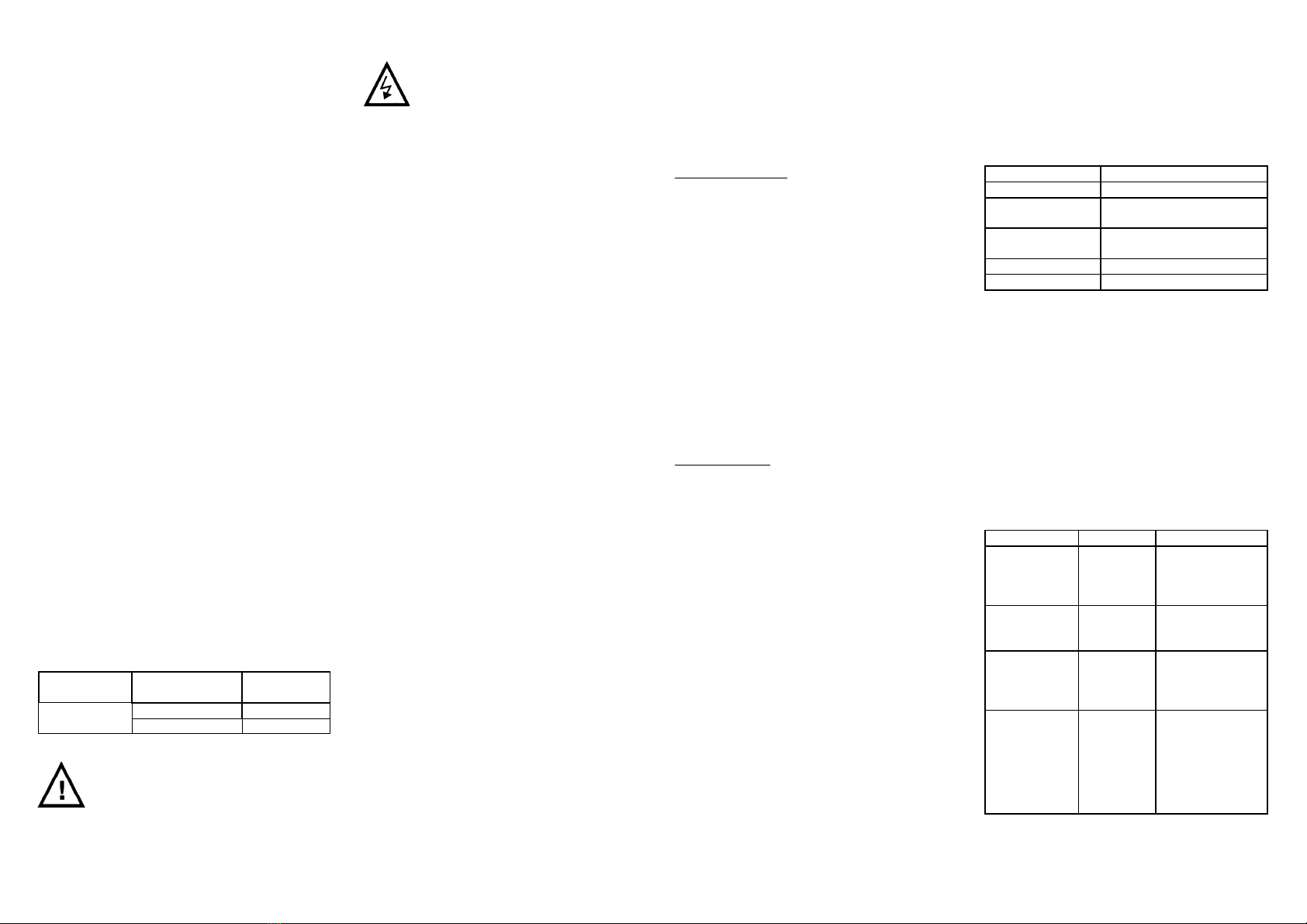
Fault finding
Fault Cause Action
The pump is not
running.
See under
heading
"Signals"
Reset fault
indication.
Check main supply
and fuses.
Pump will not
start / is running
irregular.
Impurities in
the pump.
See under heading
“Service/
Maintenance".
The pump is
running but no
flow.
Air in the
system.
Closed
valve.
Vent pump and
system.
Open valve.
Pump noisy. Pump speed
too high.
Static head
too low.
Air in
system.
Decrease set point
of control. Increase
inlet pressure.
Vent pump and
system.


