Smeg PU64 User manual

Important Safety Instruction
3
IMPORTANT SAFETY INSTRUCTIONS
READ AND SAVE THESE INSTRUCTIONS – Your Safety And the Safety of Others Are Very Important.
We have provided many important safety messages throughout this manual and on your appliance.
Read all instructions before using your appliance and always obey all safety messages.
RECOGNIZE SAFETY INFORMATION
This is a safety alert symbol. This symbol alerts you to potential hazards that can kill or hurt you and
others.
UNDERSTAND SIGNAL WORDS
A signal word – DANGER, WARNING, or CAUTION – is used with the safety-alert symbol. DANGER
identifies the most serious hazards. It means you can be killed or seriously injured if you do not
immediately follow instructions. WARNING means you can be killed or seriously injured if you do not
follow instructions. CAUTION indicates a potentially hazardous situation which, if not avoided, may
result in minor or moderate injury.
All safety messages will inform you as to potential hazards, inform you on how to reduce the risk of
injury and as to what can occur if the instructions are not followed.
IMPORTANT: Observe all government codes and ordinances.
WARNING: For your safety, the information in this manual must be followed to minimize the risk
of fire or explosion, or to prevent property damage, personal injury or death.
- This conversion kit must be installed by a qualified service agency in accordance with the
manufacturer's instructions and all applicable codes and requirements of the authority
having jurisdiction.
- The qualified service agency is responsible for the proper installation of this kit.
- The installation shall not be considered to be correct and completed until the operation of the
converted appliance is checked as specified in the manufacturer's instructions supplied with
this kit.
WARNING
FIRE HAZARD
Securely tighten all gas connections. If connected to LP, have a qualified
person ensure that the gas pressure does not exceed 14" water column.
Examples of a qualified person include licensed heating personnel,
authorized gas company personnel, and authorized service personnel.
FAILURE TO DO SO CAN RESULT IN DEATH, EXPLOSION, OR FIRE.

Conversion Kit
4
1)
Check that the main gas supply line to the range is shut off and that the
power supply cord is disconnected.
2)
Remove access cap “A” by using a screwdriver or a quarter, turning the access cap anti-clockwise.
The gas pressure regulator has two settings which are indicated on two sides of the cap. Turn the cap
and reinstall it in the regulator with "LP" visible from the outside of the regulator.
The regulator must be checked at
a minimum water column of 1 inch
(2.5 cm) above the set pressure.
The inlet pressure to the regulator
should be as follows for operation
and checking the regulator
setting: - NATURAL GAS: Set
pressure at 6” (15.2 cm). Supply
pressure of 7-14” (17.8 cm to 35.5
cm) maximum; - LP GAS:
Minimum pressure of 10” (25.4
cm). Supply pressure of 14” (35.5
cm).
The cooktop must be isolated from the gas supply piping system by closing the respective manual shut-
off valve during any pressure testing of the gas supply piping system at test pressures equal to or
greater than 1/2 psig (3.5 kPa).

Conversion Kit
5
3)
Remove all the burner components following the numerical sequence shown in the figure:
- remove all the knobs (1) by pulling them upward
- remove the grids (2), lifting up one of the two horizontal spokes
- remove the burner caps (3) and flame caps (4)
- with wrench A (available from authorized service centers), open the bayonet clamps on the burner
rings by levering on guides B
After having removed all of the above-described components, lift the surface to gain access to the
burners and gas taps.

Conversion Kit
6
4) To adjust the cooktop for LP gas or to return to Natural Gas use, refer to the tables here below.
PU 64 - Natural gas PU 64 - LP
Qt Injector Qr Qt Injector Qr Qr
BTU Ø mm BTU BTU Ø mm BTU BTU
Front Right 3800 0.82 1500 Front Right 4000 0.60 1500 0.40
Front Left 5200 0.95 1800 Front Left 5400 0.67 1800 0.40
Rear Right 10000 1.30 4000 Rear Right 10300 0.95 4000 0.58
Rear Left 7200 1.13 3000 Rear Left 7300 0.78 3000 0.50
PU 75 - Natural gas PU 75 - LP
Qt Injector Qr Qt Injector Qr Qr
BTU Ø mm BTU BTU Ø mm BTU BTU
Front Right 3800 0.82 1500 Front Right 4000 0.60 1500 0.40
Front Left 3800 0.82 1500 Front Left 4000 0.60 1500 0.40
Central A12000 1.30 4000 Central A11500 0.87 4000 0.58
B0.71 B0.48
Rear right 5200 0.95 1800 Rear right 5400 0.67 1800 0.40
Rear left 7200 1.13 3000 Front Left 7300 0.78 3000 0.50
PU 75 - Natural gas PU 75 - LP
Qt Injector Qr Qt Injector Qr Qr
BTU Ø mm BTU BTU Ø mm BTU BTU
Central
right
A12000 1.30 4000 Central
right
A11500 0.87 4000 0.58
B0.71 B0.48
Central
left
A12000 1.30 4000 Central
left
A11500 0.87 4000 0.58
B0.71 B0.48
Front Right 3800 0.82 1500 Front Right 4000 0.60 1500 0.40
Front Left 3800 0.82 1500 Front Left 4000 0.60 1500 0.40
Rear Right 7200 1.13 3000 Rear Right 7300 0.78 3000 0.50
Rear Left 5200 0.95 1800 Rear Left 5400 0.67 1800 0.40
NOTE: For reference parameters Aand Bon the central left and the
central right burners, see drawings on the right.

Conversion Kit
7
5)
Loosen screw C and push air regulator D to the bottom.
With a 7-mm wrench, remove nozzle E and replace it with the proper one
(follow the instructions on the reference tables for the type of gas to be used).
The torque wrench setting for the nozzle must not exceed 3 Nm.
Regulate the air by sliding regulator D until reaching distance “X” as
described in paragraph 6.
Lock regulator D by tightening screw C.
6)
Referred to distance “X” in mm.
PU 64 – Natural gas PU 64 – LP
Air Shutter Air Shutter
Front right 2/10” - 5 mm Front right 3/8” - 10 mm
Front left 3/16 “ - 4.5 mm Front left 1/10” - 2.5 mm
Rear right 1/8“ - 3 mm Rear right 1/10” - 2.5 mm
Rear left 5/32 “ - 3.5 mm Rear left 1/8“ - 3 mm
PU 75 – Natural gas PU 75– LP
Air Shutter Air Shutter
Front right 2/10” - 5 mm Front right 3/8” - 10 mm
Front left 2/10” - 5 mm Front left 3/8” - 10 mm
Central A1/2” - 13 mm Central A9/16” - 14 mm
B1/2” - 13 m B9/16” - 14 mm
Rear right 3/16 “ - 4.5 mm Rear right 1/10” - 2.5 mm
Rear left 5/32 “ - 3.5 mm Rear left 1/8“ - 3 mm
PU 106 – Natural gas PU 106 – LP
Air Shutter Air Shutter
Front right 2/10” - 5 mm Front right 3/8” - 10 mm
Front left 2/10” - 5 mm Front left 3/8” - 10 mm
Central
left-right
A1/2” - 13 m Central
left-right
A9/16” - 14 mm
B5/8“ - 15 mm B9/16” - 14 mm
Rear right 5/32 “ - 3.5 mm Rear right 1/8“ - 3 mm
Rear left 3/16 “ - 4.5 mm Rear left 1/10” - 2.5 mm

Conversion Kit
8
7)
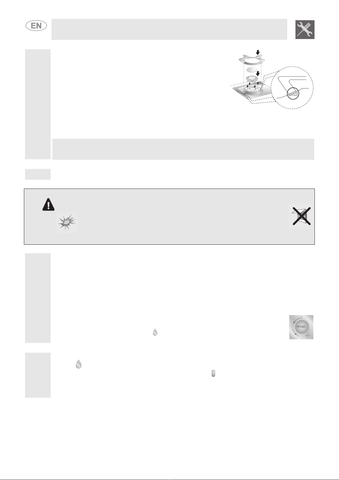
Refit the crowns, flame caps and grids on the cooktop in the following
order:
1 Fit the crowns, ensuring that they are perfectly locked into their
housing on the cooktop.
2 Fit the flame caps on the crowns, ensuring that the edges match
perfectly.
3 Fit the grids, making sure to fasten the side spokes in the special
“A” seats found on the cooktop.
These procedures must be repeated for each burner on the cooktop.
Caution: refit all flame caps in the same points from which they were removed. In fact, it is not possible to
change the flame cap positions. After refitting them, ensure that they are perfectly in place and that there
is no clearance between the cooktop and the flame caps.
8) Complete steps 3, 5 and 6 for each burner on the cooktop.
WARNING
FIRE HAZARD
- Use a soapy solution to check for proper tightness.
- Never test for gas leaks with a match or other flames.
- Failure to follow this instruction can result in death or fire
9)
Leak testing of the appliance must be conducted according to the following instructions:
Use a brush and liquid detergent to test all gas connections for leaks. Bubbles around connections
indicate a leak. If a leak appears, shut off gas valve controls and adjust connections.
Then check the connections again.
NEVER TEST FOR GAS LEAKS WITH A MATCH OR OTHER FLAMES.
Remove all of the detergent solution from the cooktop.
Electronic Ignition System - initial lighting
Cooktop burners use electronic igniters rather than standing pilots. When the cooktop control
knob is pushed in and turned to the " " position, the system lights a spark to ignite the
burner. This sparking continues until the control knob is turned to the desired setting.
10)
Check the operation of the cooktop burners. Push in and turn each control knob to the maximum flame
position ( ). The flame should light within 4 seconds.
If the burners do not light properly, turn the control knob to the position. Ensure that the burner cap is
in the proper position. Ensure that the power supply cord is plugged in and that the circuit breaker or
house fuse has not blown. Ensure that the shut-off valve is on the "ON" position. Check operation again.
If a burner does not light at this point, contact your SMEG dealer for assistance.

Conversion Kit
9
11)
Replace the components on the burner and turn the knobs on the gas tap pins.
Light the burner and set it at minimum .
Remove the knob and turn the regulation screw inside or next to the gas tap pin
(depending on the model) until you obtain a suitable minimum flame.
Replace the knob and check flame stability by rapidly turning the knob from
maximum to minimum. The flame should not go out.
If the flame appears as shown in the diagram after air setting:
the following adjustments must be made:
A: the flame is noisy and unstable and blows away from the burner, the primary air intake is open too far.
B: the flame is cloudy and dull or has yellow dots and wraps round the burner, the primary air intake is
closed too far.
C: the flame is blue, clear and stable and does not blow away from or wrap around the burner, the air is
set correctly.
12) Check flame at the maximum flame position ( ) for a blue color. It should be clean and soft in character.
No blowing or lifting of flame should occur. Occasional orange flashes are normal and reflect different
elements in the air or gas.
13) Completely fill out conversion label (part no. XXXXXXX) and attach the label to the bottom of the
cooktop beside the rating tag. Do not cover the rating tag with the conversion label.
14) At higher altitudes, no further adjustments are necessary. Derating the burners is also unnecessary.
15) Save the orifices removed from the unit along with these instructions for possible future use.
NATURAL GAS:
To convert back to Natural Gas: Follow steps 3 through 11 and replace orifices in the order in which they
were removed.
Other manuals for PU64
3
This manual suits for next models
6
Table of contents
Other Smeg Cooktop manuals

Smeg
Smeg SNZ61MFX User manual

Smeg
Smeg A3SX User manual

Smeg
Smeg SUK81MBL5 User manual

Smeg
Smeg Freestanding Gas Range C6GGXU User manual

Smeg
Smeg Dolce Stil Novo PV664LCNXAU User manual

Smeg
Smeg Portofino User manual

Smeg
Smeg Gas Cooktop PA106SX User manual

Smeg
Smeg SIHP263B User manual

Smeg
Smeg SUK61CPX5 User manual

Smeg
Smeg PGA75F-4 User manual
Popular Cooktop manuals by other brands

Bompani
Bompani BO217MA/N Instructions for the installation and use

LG
LG Studio LSCE365ST Service manual

Dacor
Dacor Distinctive DCT365 installation instructions

Whirlpool
Whirlpool SC8720ED installation instructions

Electrolux
Electrolux EI24EC15KS installation instructions

Euromaid
Euromaid IMZ96 user manual