Smeg S863VG3 User manual

IT
ISTRUZIONI PER L'INSTALLAZIONE
E L'USO DEL PIANO DI COTTURA
CRISTALLO A GAS
GB
INSTRUCTIONS FOR THE
INSTALLATION AND USE OF GLASS
GAS COOK-TOPS

10
GENERAL NOTICE
We invite you to read this instruction booklet carefully, before installing and using the equipment.
It is very important that you keep this booklet together with the equipment for any future
consultation.
If this equipment should be sold or transferred to another person, make sure that the new
user receives the booklet, so that he can learn how to operate the appliance and read the
corresponding notice.
This is a Class 3 appliance.
This appliance complies with the following Directives:
EEC 90/396 (Gas) EEC 2004/108/CE (Electromagnetic Compatibility)
2006/95/CE (Low Voltage) EEC 89/109 (Contact with foods)
The installation must be carried out by experienced and qualified personnel, in conformity with the-
regulations in force.
This appliance is not intended for use by person (including children) with reduced physical, sensory or-
mental capabilities, or lack of experience and knowledge, unless they have been given supervision or
instruction cencerning use of the appliance by a person responsible for their safety.
Children should be supervised to ensure that they do not play with the appliance.-
While the appliance is running, watch the children and make sure they neither stay near the equipment,-
nor touch the surfaces that have not cooled down completely.
Before powering the equipment, check that it is properly adjusted for the type of gas at disposal (see the-
“installation” paragraph).
Before carrying out the maintenance or cleaning the equipment, cut power supply off and make it cool-
down.
Make sure that air circulates around the gas equipment. Insufficient ventilation produces a lack of oxygen.-
In case of an intense or prolonged use of the equipment, it may be necessary to improve aeration, for-
example by opening a window or increasing the mechanical suction power, if it exists.
The products of combustion must be discharged outside through a suction hood or an electric fan (see the-
“installation” paragraph).
For any possible operation or modification, apply to an authorized Technical Assistance Centre and-
demand original spare parts.
WARNING:
If the appliance is equipped with a glass cover, the latter may shatter if heated. Turn off all the
burners and wait a few minutes before closing the cover.
The product label, with the serial number, is sticked under the hob.
The manufacturer refuses all responsibility for possible damages to things or people, resulting
from a wrong installation or from an improper, incorrect or unreasonable use of this equipment
GB

11
DESCRIPTION
MOD. S863VG3
2 Semi-rapid burner 1650 W
4 Wok burner 4000 W
7 Battery housing
8 Control knob for burner

12
IT IS NECESSARY THAT ALL THE OPERATIONS REGARDING THE INSTALLATION, ADJUSTMENT AND
ADAPTATION TO THE TYPE OF GAS AVAILABLE ARE CARRIED OUT BY QUALIFIED PERSONNEL, IN
CONFORMITY WITH THE REGULATIONS IN FORCE.
THE SPECIFIC INSTRUCTIONS ARE DESCRIBED IN THE BOOKLET SECTION
INTENDED FOR THE INSTALLER
INSTRUCTIONS FOR THE USER
USING THE BURNERS
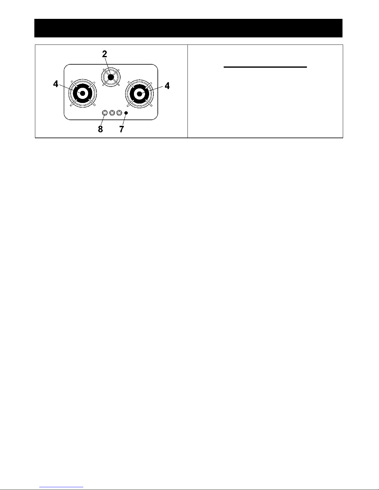
The symbols silk-screen printed on the side of the
knob indicate the correspondence between the
knob and the burner.
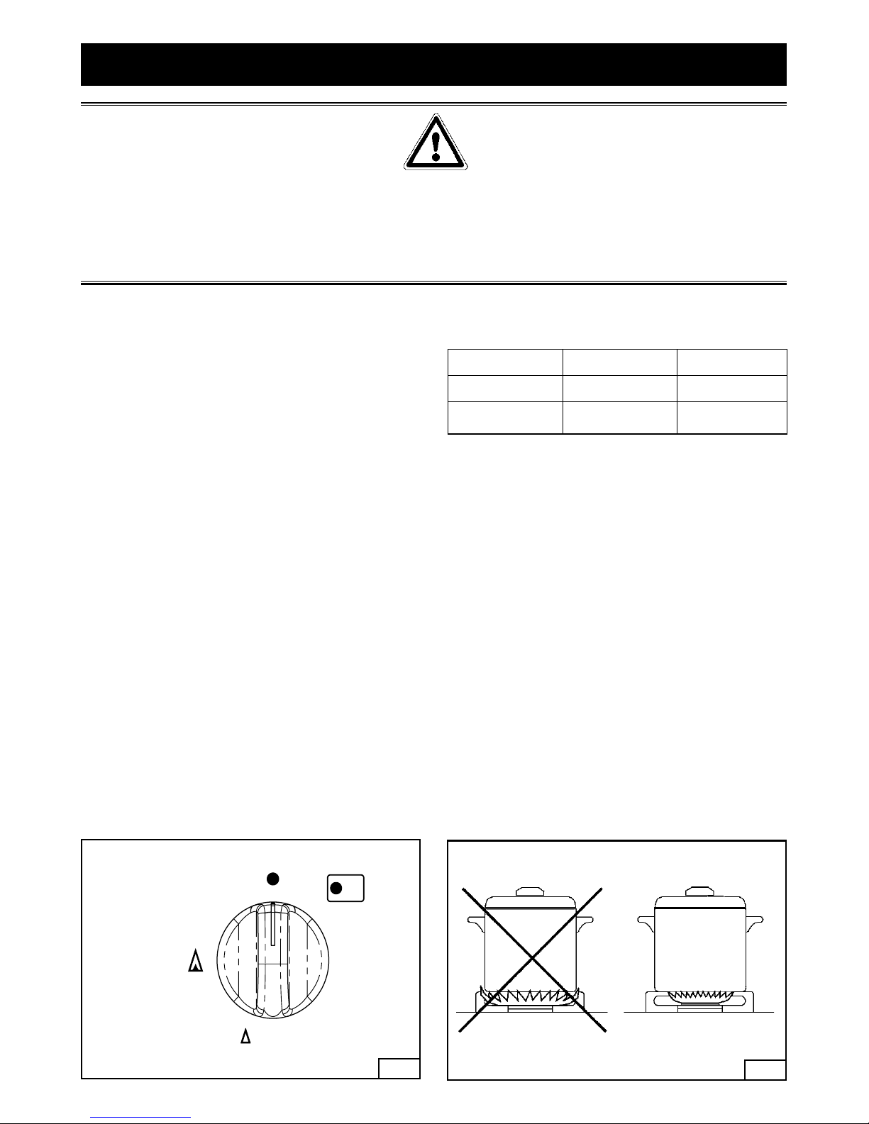
Automatic start-up with valves
Turn the corresponding knob anticlockwise up
to the maximum position (large flame, fig.1) and
press the knob.
Once the burner has been started up, keep the
knob pressed for about 6 seconds.
Using the burners
In order to obtain the maximum yield without waste
of gas, it is important that the diameter of the pot is
suitable for the burner potential (see the following
table), so as to avoid that the flame goes out of the
pot bottom (fig.2).
Use the maximum capacity to quickly make the
liquids reach the boiling temperature, and the
reduced capacity to heat food or maintain boiling.
All of the operating positions must be chosen
between the maximum and the minimum ones,
never between the minimum position and the
closing point.
The gas supply can be interrupted by turning the
knob clockwise up to the closing position.
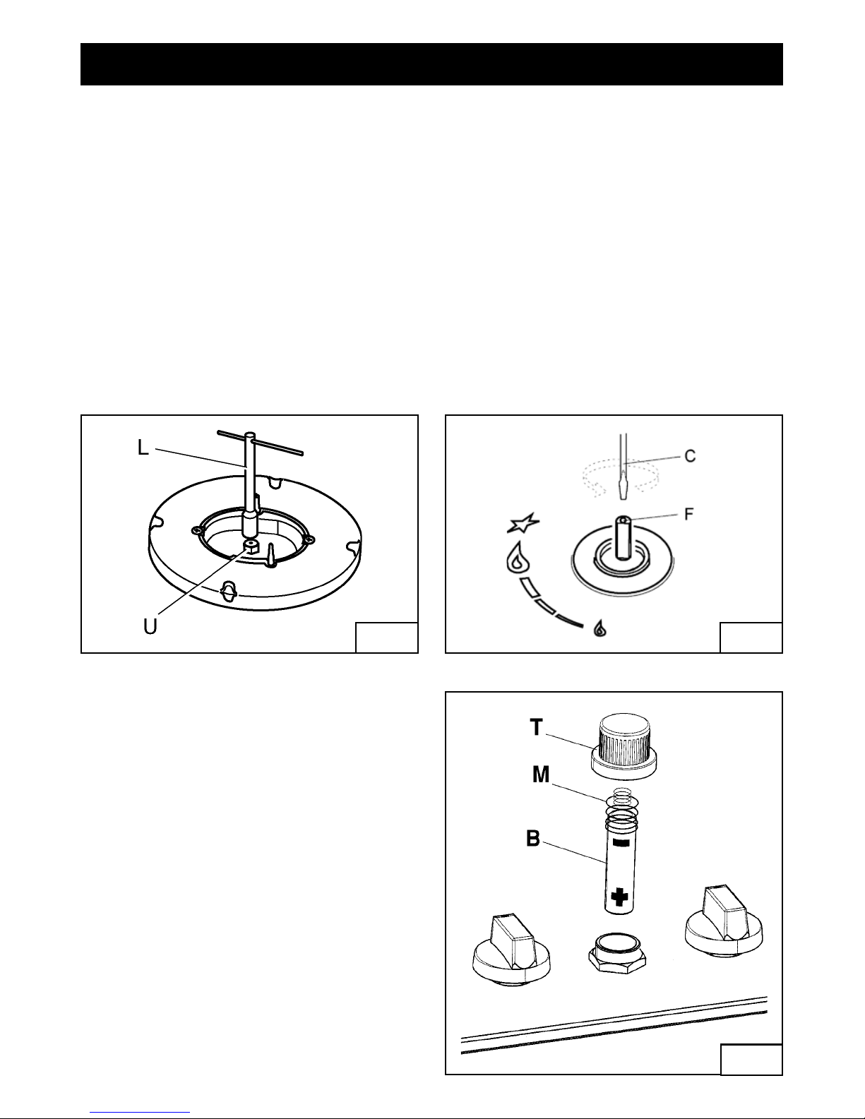
If there is no power supply, it is possible to light the
burners with matches, setting the knob to the start-
up point (large flame).
BURNERS Power W Ø of pots
Semi-rapid 1650 16 - 18 cm
Wok 4000 24 - 26 cm
Notice
When the equ- ipment is not working, always check
that the knobs are in the closing position (see
fig.1).
With the models with the safety valve, if the flame-
should blow out accidentally, the safety valve will
automatically stop the gas supply, after a few
seconds. To restore operation, set the knob to the
lighting point (large flame, fig.1).
While cooking with fat or oil, pay the utmost-
attention as these substances can catch fire when
overheated.
Do not use sprays near the appliance in operation.-
Do not place unstable or deformed pots on the-
burner, so as to prevent them from overturning or
overflowing.
Make sure that pot handles are placed properly.-
When the burner is started up, check that the-
flame is regular and, before taking pots away,
always lower the flame or put it out.
12
closing position
minimum position
maximum
position

13
13
INSTRUCTIONS FOR THE USER
CLEANING
Don't use a steam cleaner for the cleaning the
hob.
It is advisable to clean the appliance when it is
cold.
Glass platform and enamelled parts
The glass platform and all of the enamelled parts
must be washed with a sponge and soapy water
or with a light detergent.
Do not use abrasive or corrosive products.
Do not leave substances, such as lemon or tomato
juice, salt water, vinegar, coffee and milk on the
enamelled surfaces for a long time.
Burners and racks
These parts can be removed to make cleaning
easier.
The burners must be washed with a sponge and
soapy water or with a light detergent, wiped well
and placed in their housing perfectly. Make sure
that the flame-dividing ducts are not clogged.
Check that the feeler of the safety valve and the
start-up electrode are always perfectly cleaned, so
as to ensure an optimum operation.
The racks can be washed in the dishwasher.
Gas taps
The possible lubrication of the taps must be carried
out by specialized personnel, exclusively.
In case of hardening or malfunctions in the gas
taps, apply to the Customer Service.

14
IMPORTANT NOTICE
THE OPERATIONS INDICATED BELOW MUST BE FOLLOWED BY QUALIFIED PERSONNEL
EXCLUSIVELY, IN CONFORMITY WITH THE REGULATIONS IN FORCE.
THE MANUFACTURING FIRM REFUSES ALL RESPONSIBILITY FOR DAMAGES TO PEOPLE,
ANIMALS OR THINGS, RESULTING FROM THE FAILURE TO COMPLY WITH SUCH PROVISIONS.
INSTRUCTIONS FOR THE INSTALLER
INSTALLATION
Installing the top
The appliance is designed to be embedded into
heat-resistant pieces of furniture.
The walls of the pieces of furniture must resist a
temperature of 65°C besides the room one.
The equipment must not be installed near
inflammable materials, such as curtains, cloths,
etc.
Make a hole in the top of the piece of furniture, with
the dimensions indicated in fig. 3, at a distance of
at least 50 mm from the appliance border to the
adjacent walls.
Any possible wall unit over the cook-top must be
placed at a distance of at least 760 mm from the
top.
It is advisable to isolate the appliance from the
piece of furniture below with a separator, leaving a
depression space of at least 10 mm (fig.4).
34
MODEL L (mm) P (mm)
S863VG3 810 400

15
INSTRUCTIONS FOR THE INSTALLER
Fastening the top
Every cook-top is equipped with a special washer
having an adhesive side.
Remove the racks and burners from the top.-
Turn the appliance upside down and lay the-
adhesive washer S along the external border of
the glass (fig.5).
Introduce and place the cook-top in the hole made-
in the piece of furniture, then block it with the V
screws of the fastening hooks G (fig.6).
Installation room
This appliance is not provided with a device for
exhausting the products of combustion. Therefore,
it is necessary to discharge these smokes outside.
The room where this appliance is installed must
have a natural air inflow, so as to ensure a
regular gas combustion and room ventilation: the
necessary air volume must not be lower than
20m3.
Air must come from permanent openings made on
the room walls that communicate with the outside.
The section of these openings shall correspond to
at least 200 cm2.
Gas connection
Make sure that the appliance is adjusted for
the gas type available (see the label under the
appliance). Follow the instructions indicated in the
chapter “gas transformations and adjustments”
for the possible adaptation to different gases. The
appliance must be connected to the gas system
by means of stiff metal pipes or flexible steel pipes
having continuous walls, in compliance with the
regulations in force.
Gas enters the appliance through a cylindrical
threaded male gas union (1/2”).
The connection must not stress the gas ramp.
Once the installation is over, check the connection
seal with a soapy solution.
Electric connection
The appliances without supply cable, does not
require to be connected to the mains power
supply as it is provided with a low voltage ignition
generator supplied by a 1,5 V battery.
5 6

16
GAS TRANSFORMATIONS AND ADJUSTMENTS
Replacing the nozzles
If the equipment is adjusted for a type of gas that
is different from the one available, it is necessary
to replace the burner nozzles.
The choice of the nozzles to replace must be
made according to the table of the “technical cha-
racteristics”.
Act as follows:
- Remove the racks and burners.
- by means of a straight spanner L, unscrew the
nozzle U (fig.7) and substitute it with the corre-
sponding one.
- tighten the nozzle strongly.
Adjusting the burners
The lowest flame point must always be properly
adjusted and the flame must remain on even if
there is an abrupt shift from the maximum to the
minimum position.
If this is not so, it is necessary to adjust the lowest
flame point as follows:
- start the burner up
- turn the tap up to the minimum position (small
flame)
- remove the knob from the tap rod
- introduce a flat-tip screwdriver C in the hole F of
the tap (fig.8) and turn the by-pass screw up to a
proper adjustment of the lowest flame point.
As regards G30 gas burners, the by-pass screw
must be tightened completely.
7 8
Replacing the battery (fig. 9)
- Unscrew the cap T .
- Replace the battery B type alkaline AA 1,5 V
placing it in the spring Mand making sure that
the “ -” polarity faces upwards.
- Fit the battery into the battery holder and screw
down the cap T.
9

17
TECHNICAL CHARACTERISTIC TABLES
BURNERS GAS
NORMAL
PRESSURE
NOMINAL
RATE
INJECTOR
DIAMETER
TAPE
BY-PASS
DIAMETER
NOMINAL
HEAT
INPUT (W)
N° DESCRIPTION mbar g/h L/h 1/100 mm 1/100 mm MAX. MIN.
2 SEMI-RAPID
G30 30 120 65 31 1650 600
G31 37 118 65 31 1650 600
G20 20 154 97 Reg. 1650 600
4 ULTRA-RAPID
G30 30 255 94 60 4000 2100
G31 37 250 94 60 4000 2100
G20 20 334 141 Reg. 4000 2100
The manufacturing firm refuses all responsibility for any possible imprecision in this booklet, due to
misprints or clerical errors. It reserves the right to make all the changes that it will consider necessary in
its own products, without affecting the essential characteristics of functionality and safety.
This product complies with EU Directive 2002/96/EC.
The crossed-out dustbin symbol reported on the appliance indicates that the appliance
must be disposed of separately from other domestic refuse at the end of its useful life.
It must therefore be delivered to a waste recycling centre specifically for electric and
electronic equipment or returned to the retailer at the moment of purchase of a new
equivalent appliance.
The user is responsible for delivering the appliance to the appropriate collection centre at the end of its
useful life, Failure to do so may result in a fine, as provided for by laws governing waste disposal.
Differential collection of waste products for eventual recycling, treatment and environmentally friendly
disposal helps reduce possible negative effects on the environment and health, and also enables the
materials making up the product to be recycled.
For more detailed information on the available refuse collection systems, refer to the local Municipal Solid
Waste disposal centre or the shop where the product was purchased.
Producers and importers are responsible for fulfilling their obligations as regards recycling, treatment and
environmentally friendly disposal by directly or indirectly participating in the collection system.

20 COD. 208327-00 - 26.05.2009
Table of contents
Other Smeg Cooktop manuals

Smeg
Smeg SIHP294S Technical manual

Smeg
Smeg SAI90MB-MW User manual

Smeg
Smeg Built-in Electric Hob HBE64CAS User manual

Smeg
Smeg SIMU530 User manual

Smeg
Smeg PGF95SCU3 User manual

Smeg
Smeg SE70SGHLK User manual

Smeg
Smeg SSA91MFA User manual

Smeg
Smeg SA312XA User manual

Smeg
Smeg SI4642B User manual

Smeg
Smeg PV375NSA2 User manual
Popular Cooktop manuals by other brands

Kleenmaid
Kleenmaid CCT6020 Instructions for use and warranty details

New Wave Kitchen Appliances
New Wave Kitchen Appliances InductionPlate user manual

Miele
Miele KM 2257-1 Operating and installation instructions

Thermador
Thermador CEM COOKTOP use and care manual

Jenn-Air
Jenn-Air CVEX4100 Series use and care manual

MASTER KITCHEN
MASTER KITCHEN MKHG 6031-PR TC BK user manual