Smeg CS150SA User manual
3
Table of Contents
INSTRUCTIONS FOR THE INSTALLER: these are intended for the
qualified engineer who is to check the gas supply system and install,
commission and test the appliance
INSTRUCTIONS FOR THE USER: these provide recommendations for
use, a description of the controls and the correct procedures for cleaning
and maintaining the appliance
1. PRECAUTIONS FOR SAFETY AND USE ............................ 4
2. INSTALLING THE APPLIANCE ............................................ 6
3. ADAPTATION TO DIFFERENT TYPES OF GAS ............... 10
4. DESCRIPTION OF CONTROLS ......................................... 12
5. DESCRIPTION OF CONTROLS ......................................... 14
6. USING THE HOB ................................................................ 23
7. USING THE OVENS ........................................................... 25
8. USING THE "PIZZA" FUNCTION........................................ 27
9. ACCESSORIES AVAILABLE .............................................. 29
10. COOKING ADVICE ........................................................... 31
11. CLEANING AND MAINTENANCE .................................... 39
12. EXTRAORDINARY MAINTENANCE ................................ 44
THESE INSTRUCTIONS ONLY APPLY TO THE COUNTRIES OF DESTINATION WHOSE
IDENTIFICATION SYMBOLS ARE LISTED ON THE COVER OF THIS MANUAL.

4
Precautions for safety and use
1. PRECAUTIONS FOR SAFETY AND USE
THIS MANUAL IS AN INTEGRAL PART OF THE APPLIANCE. TAKE GOOD CARE
OF IT AND KEEP IT TO HAND THROUGHOUT THE COOKER'S LIFE CYCLE.
USERS ARE ADVISED TO READ THIS MANUAL AND ALL THE INSTRUCTIONS
IT CONTAINS BEFORE USING THE COOKER. ALSO KEEP THE SET OF
NOZZLES PROVIDED IN A SAFE PLACE. INSTALLATION MUST BE CARRIED
OUT BY QUALIFIED STAFF IN COMPLIANCE WITH THE RELEVANT
REGULATIONS. THIS APPLIANCE IS INTENDED FOR HOUSEHOLD USE AND
COMPLIES WITH THE EEC DIRECTIVES CURRENTLY IN FORCE. THE
APPLIANCE IS BUILT TO PROVIDE THE FOLLOWING FUNCTION: COOKING
AND HEATING FOODS; ALL OTHER USES ARE TO BE CONSIDERED
IMPROPER.
THE MANUFACTURER DECLINES ALL LIABILITY FOR USES OTHER THAN
THOSE STATED ABOVE.
NEVER LEAVE PACKAGING RESIDUES UNATTENDED IN THE HOME.
SEPARATE WASTE PACKAGING MATERIALS BY TYPE AND CONSIGN THEM
TO THE NEAREST SEPARATE DISPOSAL CENTRE.
THE APPLIANCE MUST BE CONNECTED TO EARTH IN COMPLIANCE WITH
ELECTRICAL SYSTEM SAFETY REGULATIONS.
THE PLUG TO BE CONNECTED TO THE POWER SUPPLY LEAD AND THE
RELATIVE SOCKET MUST BE OF THE SAME TYPE AND COMPLY WITH THE
RELEVANT REGULATIONS.
THE POWER SUPPLY SOCKET MUST BE ACCESSIBLE EVEN AFTER THE
APPLIANCE HAS BEEN BUILT-IN.
NEVER DISCONNECT THE PLUG BY PULLING ON THE POWER SUPPLY
LEAD.
IMMEDIATELY AFTER INSTALLATION, CARRY OUT A QUICK TEST ON THE
APPLIANCE FOLLOWING THE INSTRUCTIONS PROVIDED LATER IN THIS
MANUAL. IF THE APPLIANCE FAILS TO OPERATE, DISCONNECT IT FROM
THE ELECTRICAL MAINS AND CONTACT YOUR NEAREST SERVICE CENTRE.
NEVER ATTEMPT TO REPAIR THE APPLIANCE YOURSELF.
AFTER EACH USE OF THE APPLIACE, ALWAYS CHECK THAT THE CONTROL
KNOBS ARE TURNED TO (OFF).
NEVER PLACE FLAMMABLE OBJECTS IN THE OVENS: IF THEY SHOULD
ACCIDENTALLY BE SWITCHED ON, THIS MIGHT CAUSE A FIRE.
THE NAMEPLATE WITH THE TECHNICAL DATA, SERIAL NUMBER AND MARK
IS IN A VISIBLE POSITION IN THE STORAGE COMPARTMENT.
THE NAMEPLATE MUST NEVER BE REMOVED.

5
Precautions for safety and use
NEVER PLACE PANS WITH BOTTOMS WHICH ARE NOT PERFECTLY FLAT
AND SMOOTH ON THE HOB PAN STANDS.
THE APPLIANCE BECOMES VERY HOT DURING USE. TAKE CARE NOT TO
TOUCH THE HEATING ELEMENTS INSIDE THE OVEN.
THIS APPLIANCE MUST NEVER BE INSTALLED ON A STAND.
INSTALL THE APPLIANCE SO THAT WHEN DRAWERS OR DOORS OF UNITS
INSTALLED AT HOB HEIGHT ARE OPENED, ACCIDENTAL CONTACT WITH
PANS ON THE HOB IS NOT POSSIBLE.
NEVER USE PANS OR GRIDDLE PLATES WHICH PROJECT BEYOND THE
OUTSIDE EDGE OF THE HOB.
THE USE OF THIS APPLIANCE IS NOT PERMITTED TO PEOPLE (INCLUDING
CHILDREN) OF REDUCED PHYSICAL AND MENTAL ABILITY, OR LACKING IN
EXPERIE NCE IN THE USE OF ELECTRICAL APPLIANCES, UNLESS THEY
ARE SUPERVISED OR INSTRUCTED BY ADULTS OR PEOPLE RESPONSIBLE
FOR THEIR SAFETY.
THIS APPLIANCE IS TAGGED UNDER EUROPEAN DIRECTIVE 2002/96/EC ON
WASTE ELECTRICAL AND ELECTRONIC EQUIPMENT (WEEE).
THIS DIRECTIVE CONTAINS THE REGULATIONS GOVERNING THE
COLLECTION AND RECYCLING OF DECOMMISSIONED APPLIANCES
THROUGHOUT THE EUROPEAN UNION.
BEFORE THE APPLIANCE IS PUT INTO OPERATION, ALL THE LABELS AND
PROTECTIVE FILMS APPLIED INSIDE OR OUTSIDE MUST BE REMOVED.
The manufacturer declines all responsibility for injury or damage
caused by failure to comply with the above regulations or deriving from
tampering with even just one part of the appliance and the use of non-
original spare parts.
6
Instructions for the Installer
2. INSTALLING THE APPLIANCE
AB
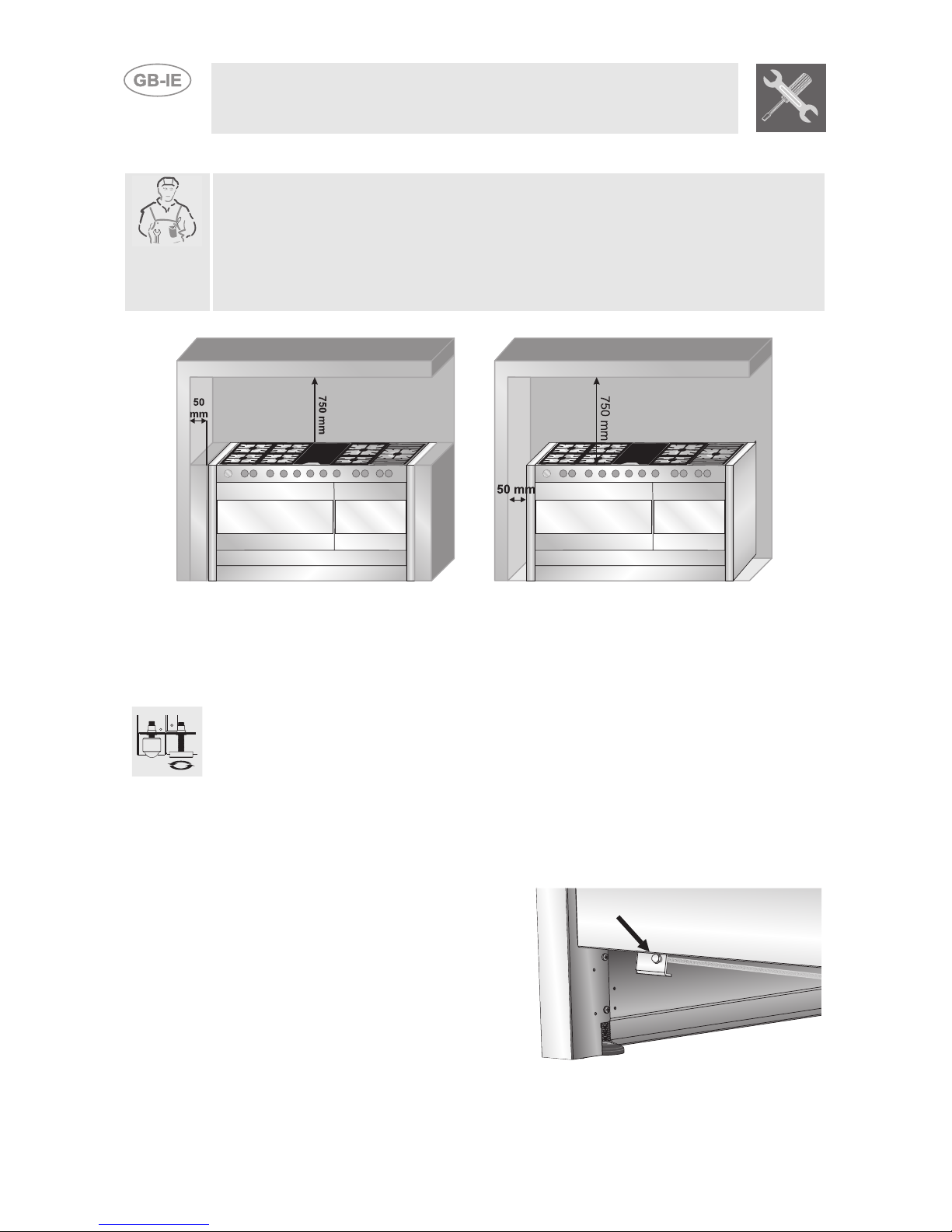
Installation must be carried out by a qualified engineer in compliance
with the relevant regulations.
It may be installed against walls one of which is higher than the worktop
surface, at least 50 mm from the side of the appliance, as shown in the
installation class drawings A and B. Wall units or extractor hoods installed
above the appliance's work-top must be at least 750 mm above it.
Built-in Appliance
(class 2 subclass 1)
Free-Standing Installation
(class 1)
2.1 Positioning and levelling the appliance
The appliance is equipped with wheels and adjustable feet to simplify the
positioning procedure. To use the front wheels, screw in the foot as shown
here, so that the appliance rests on the front wheels. However, to allow the
appliance to be moved freely it must be lifted at the back. To do this,
proceed as follows:
use a 10 socket wrench to screw in the 2 hex nuts underneath the oven
compartment: this raises the appliance either to level it or to allow it to be
moved around.
Once all procedures are complete,
retighten the front feet and the hex
nuts to set the cooker stable and
level.

7
Instructions for the Installer
2.2 Electrical connection
Check that the voltage and size of the power supply line are as specified
on the nameplate inside the storage compartment.
This nameplate must never be removed.
The plug on the end of the power supply cable and the wall socket must be
of the same type (in compliance with the relevant national standards).
Check that the power supply line is properly earthed. The use of
reductions, adapters or junctions is not recommended.
The appliance's power supply line must be fitted with an omnipolar
breaking device with contact gap of at least 3 mm, located in an easily
accessible position close to the appliance itself.
The appliance has a terminal
board on its rear.
To access it, remove the back
cover.
Make the electrical connection
in accordance with the wiring
diagram shown below.
Operation at 380-415V3N~: use a
H05RR-F or H05RN-F five-wire cable
(cable of 5 x 2.5 mm2).
Operation at 380-415V2N~: use a
H05RR-F or H05RNF four-wire cable
(cable of 4 x 4.0 mm2).
Operation at 220-240 V~: use a H05RR-F
/ H05RNF three-wire cable (cable of 3 x 6
mm2).
The earth wire (yellow-green) must be at
least 20 mm longer than the other wires at
the end for connection to the appliance.
8
Instructions for the Installer
The manufacturer declines all responsibility for injury or damage
caused by failure to comply with the above regulations or deriving from
tampering with even just one part of the appliance.
2.3 Ventilation requirements
The room containing the appliance should have an air supply in
accordance with B.S. 5440 part 2 1989.
1
All rooms require an opening window or equivalent, and some rooms
will require a permanent vent as well.
2
For room volumes up to 5 m3an air vent of 100 cm2is required.
3
If the room has a door that opens directly to the outside, and the room
exceeds 1 m3no air vent is required.
4
For room volumes between 5 m3and 10 m3an air vent of 50 cm2is
required.
5
If there are other fuel burning appliances in the same room B.S. 5440
part 2 1989 should be consulted to determine the air vent
requirements.
6
This appliance must not be installed in a bed sitting room of less than
20 m3or in a bathroom or shower room.
Windows and permanent vents should therefore not be blocked or
removed without first consulting a Corgi gas installer.
Failure to install appliances correctly is dangerous and could lead to
prosecution.
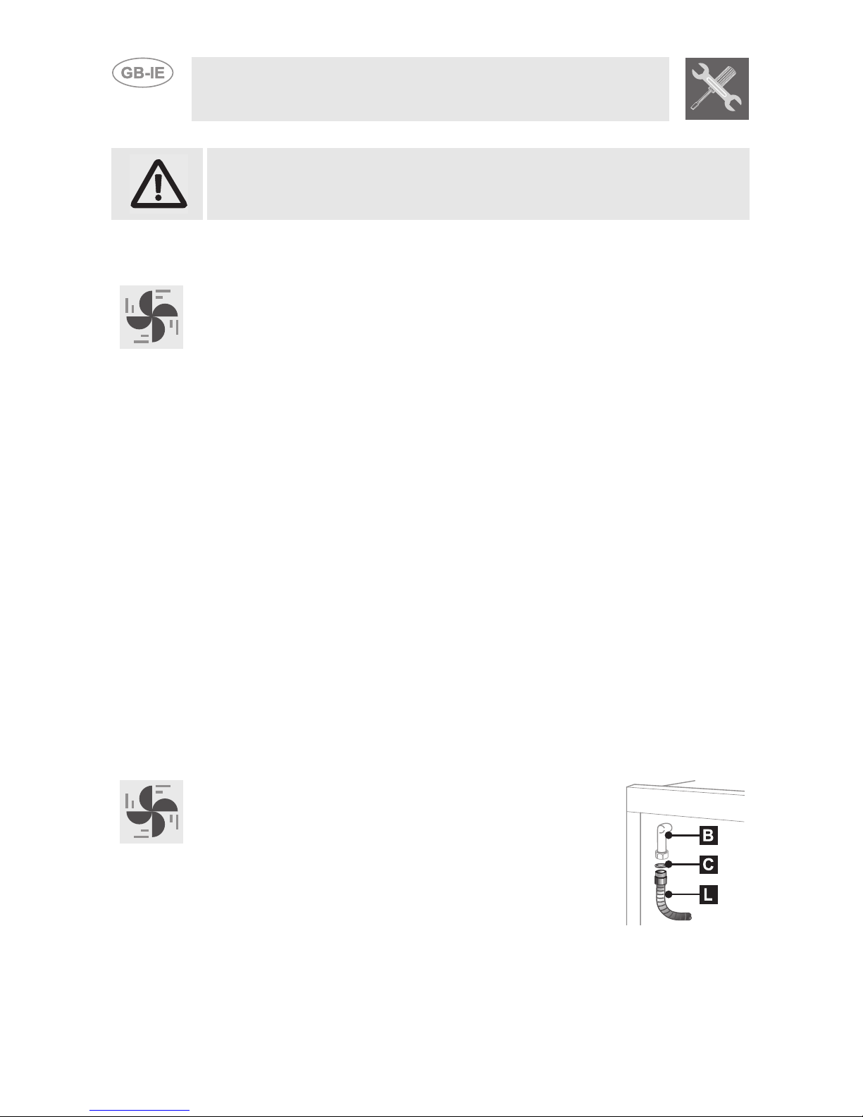
2.4 Connecting to natural and LPG gas (Please see connection
diagram)
Make the connection to the appliance using flexible
bayonet style hose in accordance to B.S. 669. The hose
connection at the rear of the appliance has a 1/2" BSP
internal thread. Please use seal Cbetween the flexible
connection Land the appliance supply tube B. When
making the connection, make sure that no stress of any
kind is applied to the cooker and that the hose does not
touch any sharp edges.
If connecting to LPG the bayonet hose must have red bands on it.
9
Instructions for the Installer
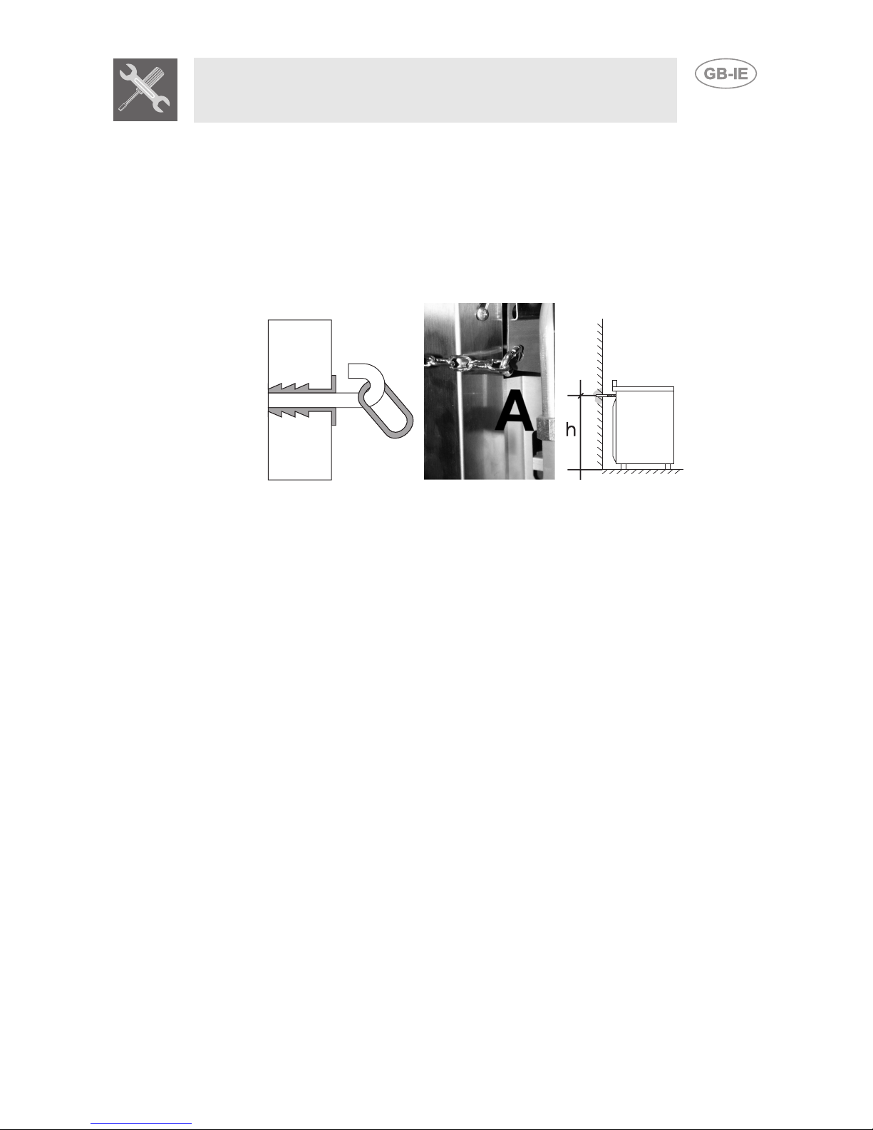
2.5 Instruction for wall fixing (only on some models)
1
Fix the screw to the wall and hook the chain (B);
2
Hook the chain to the hole positioned at the rear of the cooker by the
gas pipe (A);
3
Once the chain is in position, push the cooker against the wall;
4
The height of the screw hole from floor level must not exceed 800 mm
(C).
ABC
10
Instructions for the Installer
3. ADAPTATION TO DIFFERENT TYPES OF GAS
Before performing any cleaning or maintenance work, switch off the
power supply to the appliance.
The cooking hob of the cooker is preset for G20 natural gas at a pressure
of 20 mbar. In the case of functioning with other types of gas the burner
nozzles must be changed and the minimum flame adjusted on the gas
taps. Replace the burner nozzles as indicated in the table of the gas to be
used.
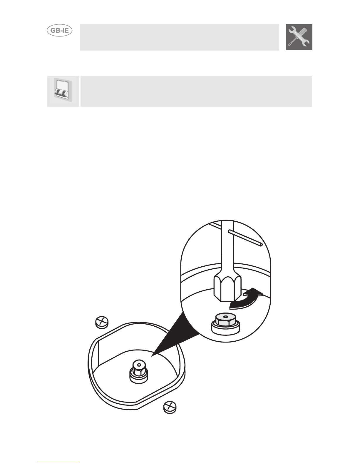
3.1 Changing nozzles
1
Extract the grids and remove all the caps and flame-spreader crowns;
2
unscrew the burner nozzles with a 7 mm socket wrench;
3
proceed with replacing the burner nozzles in accordance with the table
for the gas in question.

11
Instructions for the Installer
3.2 Burner and nozzle characteristics table
Burner
Rated
heating
capacity
(kW)
LPG – G30/G31 28/37 mbar
(drawing ref. X238)
Nozzle
diameter
1/100 mm
By-pass
Mm
1/100
Reduced
flowrate
(W)
Flowrate
g/h G30
Flowrate
g/h G31
Auxiliary 1.05 50 30 400 76 75
Semi rapid 1.8 65 33 500 131 129
Rapid 3.0 85 45 800 218 215
Fish Burner 1.9 68 45 800 138 136
Ultra rapid 4.0 100 65 1600 291 286
UR2 Inner ring 1.0 46 30 400 73 71
UR2 Outer ring 3.6 68+68 65 1600 284 250
Burner
Rated
heating
capacity
(kW)
NATURAL GAS – G20 20 mbar
Nozzle diameter
1/100 mm
Drawing
Ref.
Reduced flowrate
(W)
Auxiliary 1.05 72 (X) 400
Semi rapid 1.8 97 (Z) 500
Rapid 3.0 115 (Y) 800
Fish Burner 1.9 94 (X) 800
Ultra rapid 4.0 135 (K) 1600
UR2 Inner ring 1.0 70 (X) 400
UR2 Outer ring 3.6 102 +102 (Z) 1600
3.3 Hob burner layout
BURNERS
1
Auxiliary
2
Semi rapid
3
Rapid
4
WOK
5
Fishpan

12
Instructions for the Installer
4. DESCRIPTION OF CONTROLS
After changing the nozzles, put the pan stands, the burner caps and flame
diffuser rings back in place.
After adjusting for use of a gas other than the gas used for testing the
appliance, replace the gas setting label on the appliance with the label for
the new gas. The label is supplied in the bag with the nozzles.
4.1 Adjusting the minimum setting for natural gas
Light the burner and turn it to the minimum setting
Remove the gas tap knob and adjust the regulator
screw inside or beside the tap rod (depending on the
model) until an even minimum flame is obtained. Put
the knob back in place and check the stability of the
burner flame (the flame must not go out when the
knob is turned quickly from the maximum to the
4.2 Adjusting the minimum for bottled gas
To adjust the minimum level when using bottled gas, the adjuster screw
inside or beside the tap rod must be turned fully clockwise (depending on
the models).
The diameters of the bypasses for each individual burner are stated in
point "3.2 Burner and Nozzle Data Tables".
Table of contents
Other Smeg Range manuals


