Smeg SSA60MFX User manual

Contents
3
1INSTRUCTIONS FOR SA
F
E AND PROPER US
E
_
______________________________
4
2INSTALLATION OF THE APPLIANCE ________________________________________6
3ADAPTATION TO DIFFERENT TYPES OF GAS ________________________________9
4FINAL OPERATIONS ____________________________________________________12
5DESCRIPTION OF FRONT PANEL CONTROLS _______________________________14
6USE OF THE COOKING HOB______________________________________________16
7USE OF THE OVEN _____________________________________________________19
8ELECTRONIC PROGRAMMER ____________________________________________22
9CLEANING AND MAINTENANCE ___________________________________________24
10 EXTRAORDINARY MAINTENANCE _________________________________________26
THESE INSTRUCTIONS ARE VALID ONLY FOR END USER COUNTRIES WHOSE IDENTIFICATIO
N
SYMBOLS APPEAR ON THE COVER OF THIS MANUAL.
INSTRUCTIONS FOR THE INSTALLER: these are for the qualified technician who must carry out a
suitable check of the gas system, install the appliance, set it functioning and carry out an inspection test.
INSTRUCTIONS FOR THE USER: these contain user advice, description of the commands and the
correct procedures for cleaning and maintenance of the appliance.
@
Further information about the products can be found at www.smeg.it

Introduction
4
1INSTRUCTIONS FOR SAFE AND PROPER USE
THIS MANUAL IS AN INTEGRAL PART OF THE APPLIANCE AND THEREFORE MUST BE KEPT
IN ITS ENTIRETY AND IN AN ACCESSIBLE PLACE FOR THE WHOLE WORKING LIFE OF THE
COOKER. WE ADVISE READING THIS MANUAL AND ALL THE INSTRUCTIONS THEREIN
BEFORE USING THE COOKER. ALSO KEEP THE SERIES OF NOZZLES SUPPLIED.
INSTALLATION MUST BE CARRIED OUT BY QUALIFIED PERSONNEL IN ACCORDANCE WITH
THE REGULATIONS IN FORCE. THIS APPLIANCE IS INTENDED FOR DOMESTIC USES AND
CONFORMS TO CURRENT REGULATIONS IN FORCE. THE APPLIANCE HAS BEEN BUILT TO
CARRY OUT THE FOLLOWING FUNCTIONS: COOKING AND HEATING-UP OF FOOD. ALL
OTHER USES ARE CONSIDERED IMPROPER.
THE MANUFACTURER DECLINES ALL RESPONSIBILITY FOR IMPROPER USE.
DO NOT LEAVE THE PACKING IN THE HOME ENVIRONMENT. SEPARATE THE VARIOUS
WASTE MATERIALS AND TAKE THEM TO THE NEAREST SPECIAL GARBAGE COLLECTION
CENTRE.
IT IS OBLIGATORY FOR THE ELECTRICAL SYSTEM TO BE GROUNDED ACCORDING TO THE
METHODS REQUIRED BY SAFETY RULES.
WHEN LINKING UP TO MAINS BY PLUG AND SOCKET, MAKE SURE THAT BOTH ARE
COMPATIBLE AND CONNECT BY MEANS OF A POWER CABLE COMPLYING WITH
APPLICABLE REGULATIONS.
THE SOCKET MUST BE ACCESSIBLE AFTER THE APPLIANCE HAS BEEN BUILT IN.
NEVER UNPLUG BY PULLING ON THE CABLE.
IMMEDIATELY AFTER INSTALLATION CARRY OUT A BRIEF INSPECTION TEST OF THE
APPLIANCE, FOLLOWING THE INSTRUCTIONS BELOW. SHOULD THE APPLIANCE NOT
FUNCTION, DISCONNECT IT FROM THE SUPPLY AND CALL THE NEAREST TECHNICAL
ASSISTANCE CENTRE.
NEVER ATTEMPT TO REPAIR THE APPLIANCE.
WHEN NOT IN USE, MAKE SURE THAT THE CONTROL KNOBS ARE IN THE CORRECT (OFF)
POSITION .
NEVER PUT INFLAMMABLE OBJECTS IN THE OVEN: THEY COULD BE ACCIDENTALLY
LIGHTED AND CAUSE FIRES.
THE I.D. PLATE WITH TECHNICAL DATA, REGISTRATION NUMBER AND BRAND NAME IS
POSITIONED VISIBLY IN THE STORAGE COMPARTMENT.
THE PLATE MUST NOT BE REMOVED.
DO NOT PUT PANS WITHOUT PERFECTLY SMOOTH AND FLAT BOTTOMS ON THE COOKING
hob GRIDS.
DO NOT USE CONTAINERS OR BROILERS THAT EXTEND BEYOND THE OUTER PERIMETER
OF THE HOB.

Introduction
5
LOWER THE GLASS COVER SLOWLY AND BY HAND.
WARNING: THE GLASS COVER MAY SHATTER IF IT OVERHEATS. SWITCH OFF ALL RINGS
AND WAIT FOR THEM TO COOL DOWN BEFORE CLOSING THE COVER.
DURING USE THE APPLIANCE BECOMES VERY HOT. TAKE CARE NOT TO TOUCH THE
HEATING ELEMENTS INSIDE THE OVEN.
THE APPLIANCE IS DESIGNED FOR USE BY ADULTS. DO NOT ALLOW CHILDREN TO GO
NEAR OR PLAY WITH IT.
WHEN OPERATING THE GRILL ALL ACCESSIBLE PARTS COULD BECOME VERY HOT: KEEP
OUT OF THE WAY OF CHILDREN.
IF THE APPLIANCE IS TO BE POSITIONED ON A PLATFORM IT MUST BE INSTALLED IN SUCH
A WAY AS TO PREVENT IT FROM SLIPPING OFF THE FORMER.
INSTALL THE APPLIANCE SO THAT WHEN DRAWERS OR DOORS OF UNITS INSTALLED AT
HOB HEIGHT ARE OPENED, ACCIDENTAL CONTACT WITH PANS ON THE HOB IS NOT
POSSIBLE.
THIS APPLIANCE IS MARKED ACCORDING TO THE EUROPEAN DIRECTIVE 2002/96/EC ON
WASTE ELECTRICAL AND ELECTRONIC EQUIPMENT (WEEE).
THIS GUIDELINE IS THE FRAME OF A EUROPEAN-WIDE VALIDITY OF RETURN AND
RECYCLING ON WASTE ELECTRICAL AND ELECTRONIC EQUIPMENT.
BEFORE THE APPLIANCE IS PUT INTO OPERATION, ALL THE LABELS AND PROTECTIVE
FILMS APPLIED INSIDE OR OUTSIDE MUST BE REMOVED.
The manufacturer declines all responsibility for damage to persons or things caused by non-
observance of the above prescriptions or by interference with any part of the appliance or by the use
of non-original spares.

Instruction for the installer
6
2INSTALLATION OF THE APPLIANCE
It is the law that all gas appliances are installed by competent persons. Depending on the type of
installation, it is in class 1 (Fig. A) or class 2 - sub-class 1 (Fig. B-C)
Corgi gas installers are approved to work to safe and satisfactory standards. All gas installation,
servicing and repair work must be in accordance with the gas safety regulations 1984 (installation
and use) as amended 1990.
It can be placed against walls higher than the hob, at a distance of at least 50 mm from the side of
the appliance, as shown in the drawings A and B relating to the installation classes. Wall units or
extractor hoods located above the hob must be at least 750 mm away from it.
AB
Built-in appliance Free-standing installation
AB
Built-in appliance Free-standing installation
C
The appliances with a gas bottle compartment and electric oven can only be installed as
class 1 (see fig. B).

Instruction for the installer
7
2.1 Electrical connection
Make sure that the power line voltage matches the specifications indicated on the rating plate
located inside the storage compartment.
This rating plate must never be removed.
If the appliance is hooked-up to the supply by means of a fixed connection, install a multipolar cut-
out device on the line, with contact opening distance equal to or greater than 3 mm, located near the
appliance and in an easily reachable position.
Hook-up to the supply may be fixed or with plug and socket. In the latter case the plug and socket
must be suitable for the cable employed and conform with the regulations in force. Regardless of the
type of connection, earthing of the appliance is absolutely obligatory. Before connection make sure
that the supply line is suitably earthed. Avoid the use of reducers, adapters or shunts.1
For operation on 220-240 V
∼
:use an H05RR-F or H05V2V2-F type
three-core cable (3 x 2.5 mm2on 90 cm models or 3 x 1.5 on 60 cm
models).
For operation on 380-415 V 2N
∼
(only for 90 cm models): use an
H05RR-F or H05V2V2-F type four-core cable (4 x 1.5 mm2).
For operation on 380-415 V 3N
∼
(only for 90 cm models): use an
H05RR-F or H05V2V2-F type five-core cable (5 x 1.5 mm2).
The cable end to be connected to the appliance must be provided with
an earth wire (yellow-green) at least 20 mm longer.
2.2 Ventilation requirements
The room containing the appliance should have an air supply in accordance with B.S. 5440 part 2
1989.
1. All rooms require an opening window or equivalent, and some rooms will require a permanent
vent as well.
2. For room volumes up to 5 m3an air vent of 100 cm2is required.
3. If the room has a door that opens directly to the outside, and the room exceeds 1 m3no air vent
is required.
4. For room volumes between 5 m3and 10 m3an air vent of 50 cm2is required.
5. If there are other fuel burning appliances in the same room B.S. 5440 part 2 1989 should be
consulted to determine the air vent requirements.
6. This appliance must not be installed in a bed sitting room of less than 20 m3or in a bathroom or
shower room.
Windows and permanent vents should therefore not be blocked or removed without first consulting a
Corgi gas installer.
Failure to install appliances correctly is dangerous and could lead to prosecution.

Instruction for the installer
8
2.3 Connecting to natural and LPG gas
(Please see connection diagram)
Make the connection to the appliance using flexible bayonet style hose in
accordance to B.S. 669. The hose connection at the rear of the appliance has a
½” BSP internal thread. Please use seal Cbetween the flexible connection Land
the appliance supply tube B. When making the connection, make sure that no
stress of any kind is applied to the cooker and that the hose does not touch any
sharp edges.
If connecting to LPG the bayonet hose must have red bands on it.
2.3.1 Connection to the gas bottle inside the compartment in the cooker (on some models
only)
Open the side door and put in a gas bottle (max. 15
kg). Fit one end of the pipe to the pipe holder and fix
it to one of the clamps supplied. Insert the pipe into
the bottle compartment through the hole in the back
of the cooker as shown in the diagram here. Fit the
free end of the pipe to the pressure regulator on the
gas bottle: fix it with the second clamp. Check for
any leaks using a soapy solution, never with a
live flame.
To connect the cooker to a gas bottle, use a piece of regulation rubber pipe 1.4 m (
±
0.05 m) long
2.3.2 Bottled gas connection (Only on some models)
Use a pressure regulator complaint with the relevant standards and make the connection to the gas cylinder in
accordance with the relevant regulations.
Make sure that the gas supply pressure is as stated in the table in point "3.2/3.3 Burner and Nozzle Data Tables".
Screw the small hose connector Fonto the large hose connector Aand
connect the resulting unit to the gas union B(or use the hose connector
Gfor connection straight to the gas union B) and fit the seal C. Fit the
ends of the rubber hose Honto the hose connector A+F (or G) and to
the outlet union of the pressure reducer on the gas cylinder. Fix the end
of the hose Hto the hose connector A+F (or G) using the regulation
hose clamp I .
The hose connector Gshown is not supplied with the appliance. Use only hose connectors
compliant with the relevant regulations.

Instruction for the installer
9
3ADAPTATION TO DIFFERENT TYPES OF GAS
Before performing any cleaning or maintenance work, detach the appliance from the electrical socket.
The cooker hob is set for natural gas G20 (2H) at a pressure of 20 mbar for cookers with maxi oven,
and for LPG G30/G31 (3+) at a pressure of 28/37 mbar for cookers with gas-bottle compartments. In
the case of functioning with other types of gas the burner nozzles must be changed and the
minimum flame adjusted on the gas taps. To change the nozzles, proceed as described below.
3.1 Replacement of nozzles on the hob
This operation requires no primary air regulation.
1. Extract the grids and remove all the caps and flame-spreader crowns;
2. unscrew the burner nozzles with a 7 mm socket wrench;
3. replace the nozzles according to the type of gas to be used and the description in paragraph “3.2
/ 3.3 Burner and nozzle characteristics table”.
4. Replace the burners in the correct position.

Instruction for the installer
10
3.2 Burner and nozzle characteristics table (50-60 cm models)
Burner
Rated
heating
capacity
(kW)
LPG –G30/G31 28/37 mbar
Nozzle
diameter
1/100 mm
Reduced
flowrate
(W)
Flowrate
g/h G30
Flowrate
g/h G31
Auxiliary 1.0 50 350 73 71
Semi-rapid 1.8 65 450 131 129
Triple crown 3.2 91 1500 233 229
Burner
Rated
heating
capacity
(kW)
NATURAL GAS – G20 20 mbar
Nozzle diameter
1/100 mm
Reduced Flowrate
(W)
Auxiliary 1.0 72 350
Semi-rapid 1.8 97 450
Triple crown 3.2 133 1500
3.3 Arrangement of burners on cooking hob
BURNERS
1. Auxiliary
2. Semi-rapid
4. Triple crown

Instruction for the installer
11
3.4 Burner and nozzle characteristics table (90 cm models)
Burner
Rated
heating
capacity
(kW)
LPG –G30/G31 28/37 mbar
Nozzle
diameter
1/100 mm
Reduced
flowrate
(W)
Flowrate
g/h G30
Flowrate
g/h G31
Auxiliary 1 50 350 73 71
Semi-rapid 1.8 65 450 131 129
Rapid 3 85 800 218 214
Triple crown 3.2 91 1500 233 229
Oven 1.9 68 800 138 136
Burner
Rated
heating
capacity
(kW)
NATURAL GAS – G20 20 mbar
Nozzle diameter
1/100 mm
Reduced Flowrate
(W)
Auxiliary 1 72 350
Semi-rapid 1.8 97 450
Rapid 3 115 800
Triple crown (4) 3.5 133 1500
Triple crown (8) 3.5 140 1500
Oven 3.2 130 850
3.5 Arrangement of burners on cooking hob
BURNERS
1. Auxiliary
2. Semi-rapid
3. Rapid (60 X 60)
4. Triple crown
5. Large electric hob (1500W)
6. Small electric hob (1000W)
8. Triple crown

Instruction for the installer
12
4FINAL OPERATIONS
After replacing the nozzles, reposition the flame-spreader crowns, the burner caps and the grids.
Following adjustment to a gas other than the preset one, replace the gas adjustment label fixed to
the appliance with the one corresponding to the new gas. This label is in the packet together with the
nozzles.
4.1 Regulation of the hob burner minimum level for natural gas
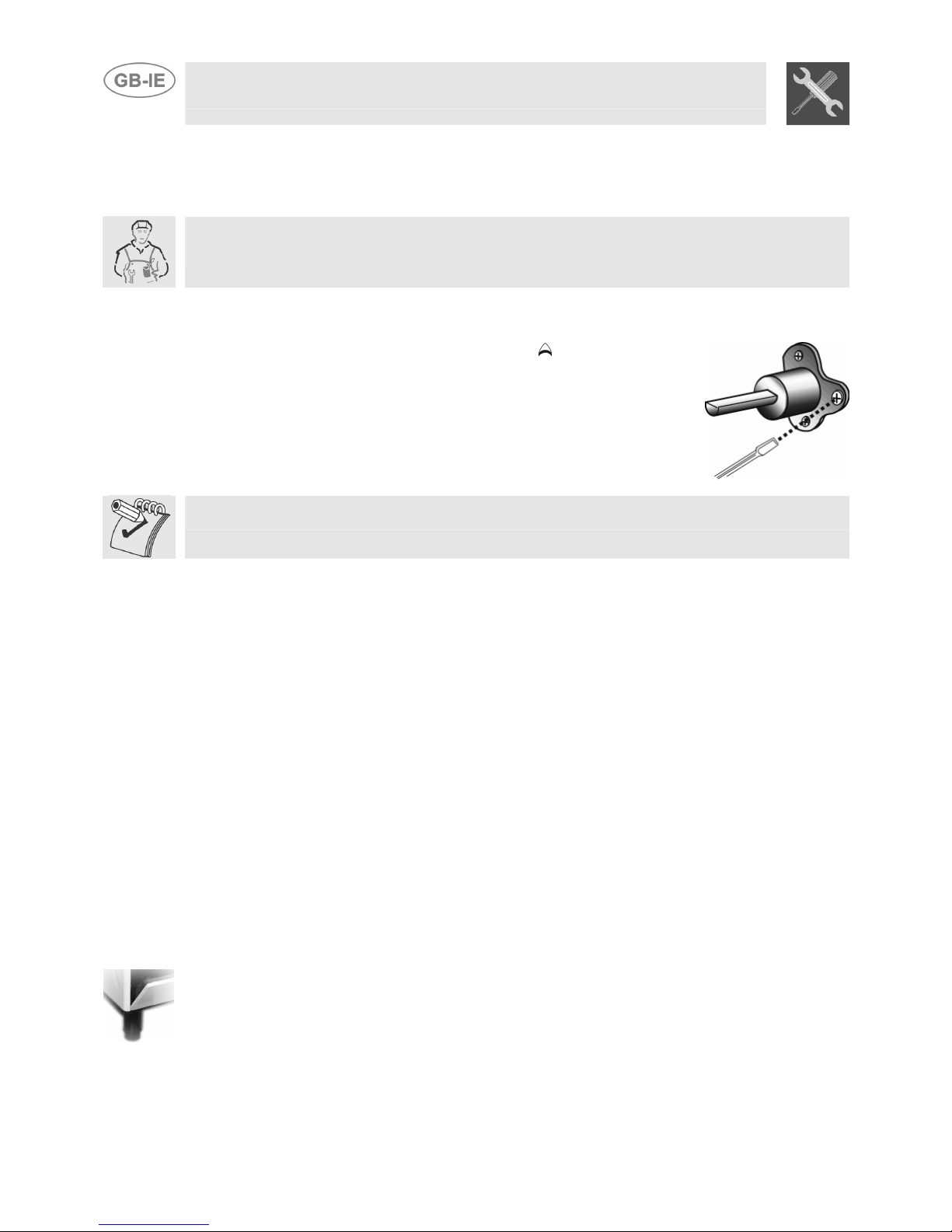
Light the burner and turn it to the minimum position . Extract the gas
tap knob and turn the adjustment screw at the side of the tap rod until the
correct minimum flame is achieved.
Replace the knob and check burner flame stability: (rapidly turning the
knob from maximum to minimum position, the flame should not go out).
Repeat the operation on all the gas taps.
For models with valves, keep the knob at minimum level for about 1 minute to keep the flame lit and
to activate the safety device.
4.2 Regulation of the hob burner minimum level for LPG
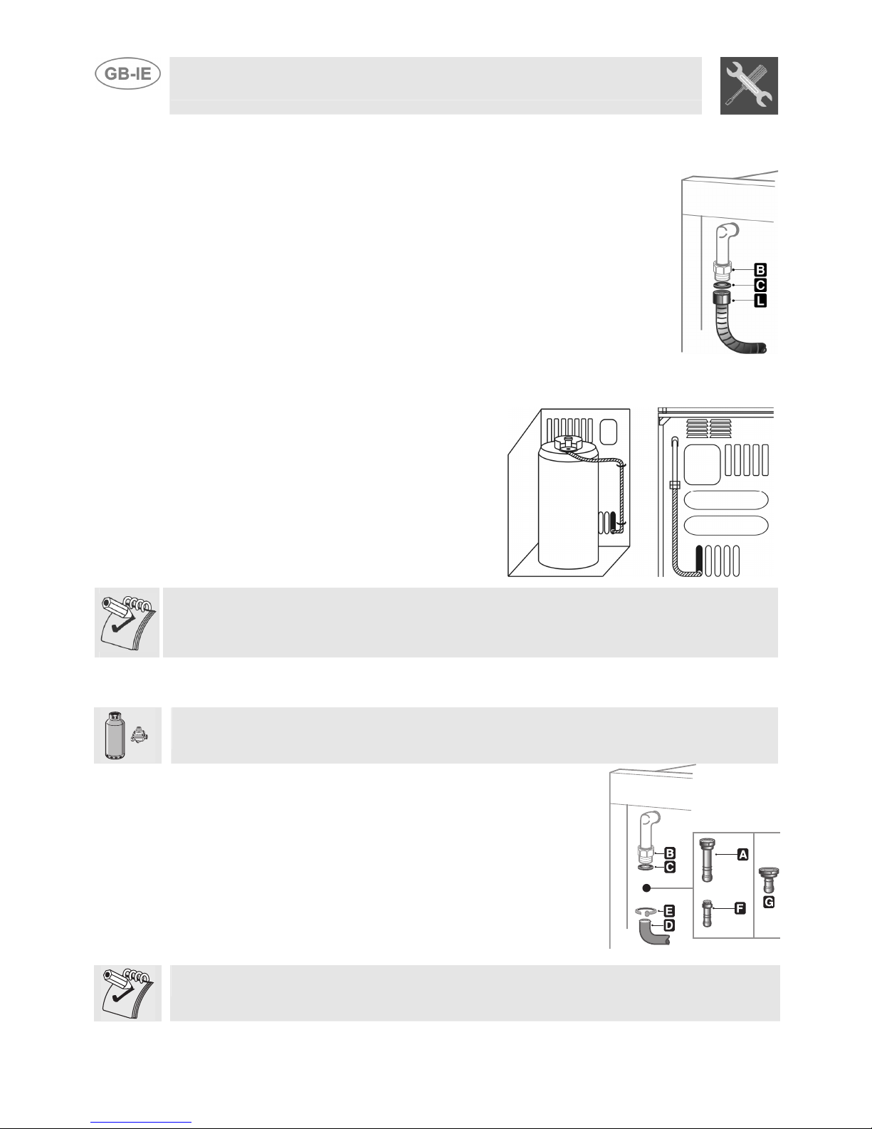
For regulating the minimum with LPG, the screw at the side of the tap rod must be turned clockwise
all the way.
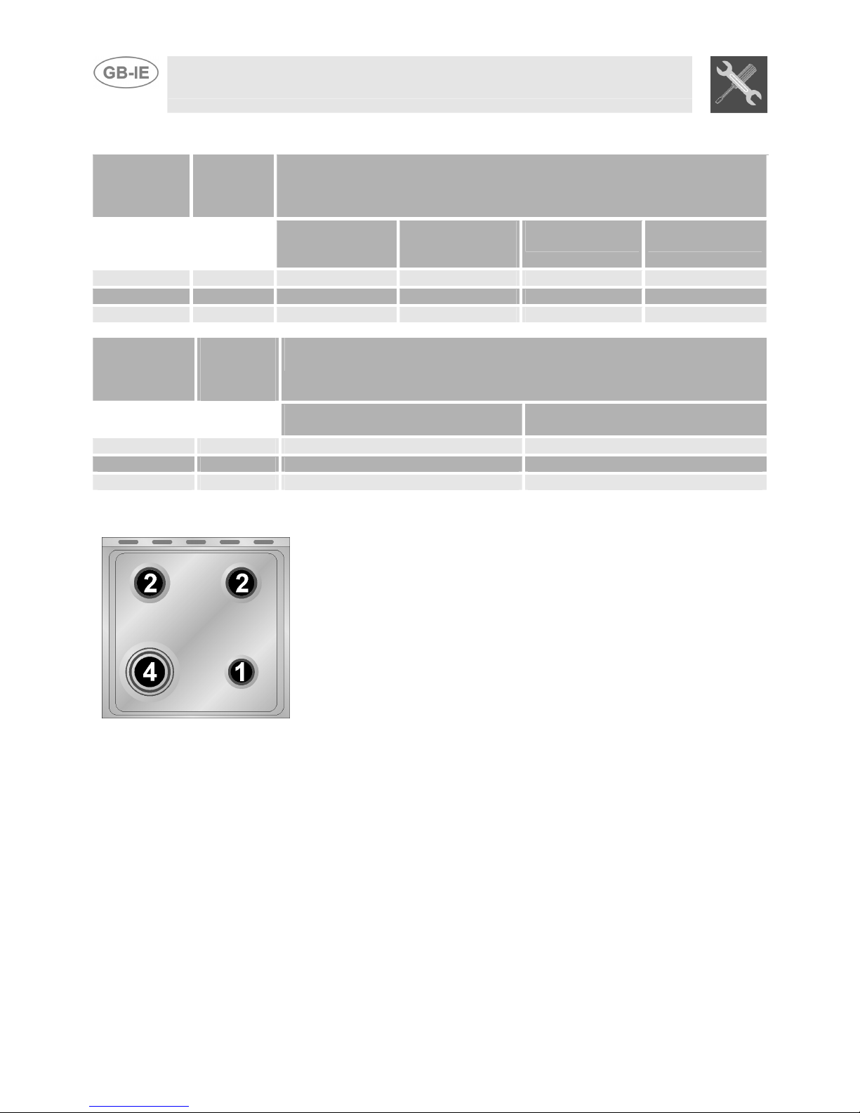
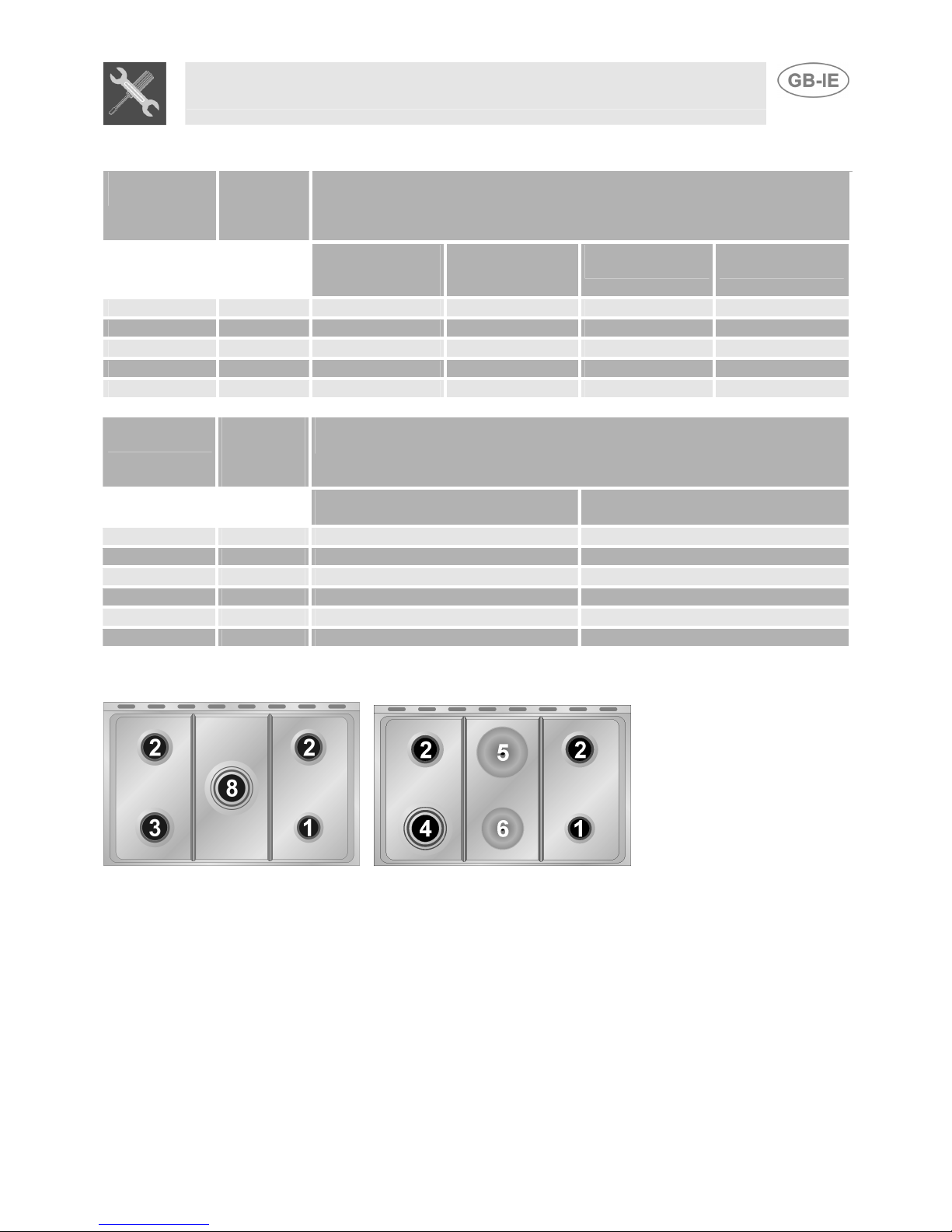
The bypass diameters for each individual burner are shown in paragraph “3.2/3.3 Burner and nozzle
characteristics table”. Once the regulation has been completed, replace the seal on the by-passes
using paint or similar materials.
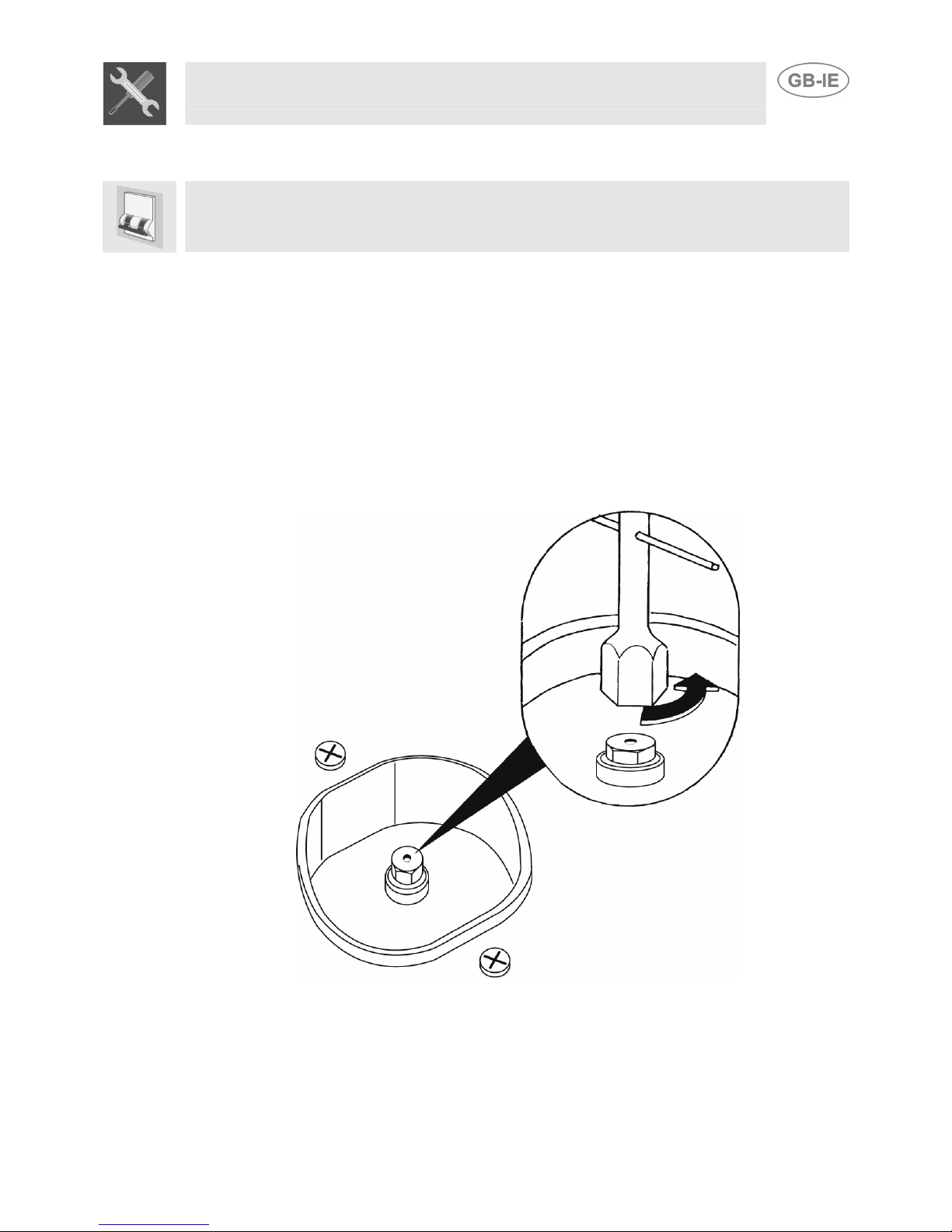
4.3 Regulation of the oven burner minimum level
The oven thermostat is equipped with a by-pass to regulate the minimum level, which is visible
underneath the thermostat knob.
When the gas type is changed, the by-pass should be regulated as follows:
1. Turn on the oven burner to maximum for 10/15 minutes with the door closed and without the
floor. Turn the knob to the minimum temperature, remove the knob and regulate using a flat
screwdriver.
2. For LPG turn the by-pass screw clockwise as far as it will go. The by-pass diameter is shown in
the paragraph “3.2/3.3 Burner and nozzle characteristics table”.
3. For natural gas, regulate the by-pass so that turning the thermostat knob from minimum to
maximum the flame remains stable and constant. Once the regulation has been completed,
replace the seal on the by-pass using paint or similar materials. Close the oven door and make
sure that the burner stays on minimum.
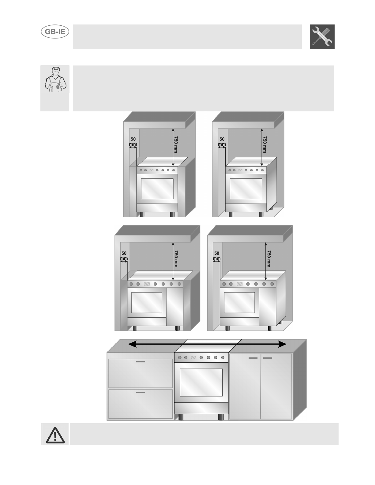
4.4 Positioning and levelling of the appliance
Having carried out the electricity and gas hook-up, level the appliance using the four adjustable legs.
For best cooking the appliance must be perfectly level.

Instruction for the installer
13
4.5 Mounting the rear top skirtboard (where applicable)
•Loosen nuts B.
•Position the skirt above the top, taking care
to align pins Cwith holes D.
•Secure the skirt to the top by tightening
screws A.
4.6 Positioning and levelling of the appliance
Having carried out the electricity and gas hook-up, level the appliance using the four adjustable legs.
For best cooking the appliance must be perfectly level.
Depending on the model you have purchased, the foot height adjustment range may vary from 70 to
95 mm and from 110 to 160 mm. These heights refer to the distance between the highest point of
the foot (fixed part) and the lowest point (movable part which rests on the floor).
4.7 Wall fixing
•Stretch out the chain attached to the cooke
r
horizontally so that the other end touches the
wall.
•Mark the wall in the position where the hole is
to be drilled.
•Drill the hole, insert a wall plug and attach the
chain.
•Move the cooker up against the wall.

Instruction for the user
14
5DESCRIPTION OF FRONT PANEL CONTROLS
A
12 3012 30
150
175
225
125
245
260
200
100
50
A
12 3012 30
150
175
225
125
245
260
200
100
50
A
12 3012 30
150
175
225
125
245
260
200
100
50
1
2
3
4
5
61
2
3
4
5
6
All the oven controls are grouped together on the front panel. The table below provides a description
of the symbols used.
FRONT RIGHT BURNER
FRONT CENTRAL BURNER
BACK RIGHT BURNER
CENTRAL BURNER
BACK LEFT BURNER
ELECTRIC OVEN FUNCTION
KNOB
FRONT LEFT BURNER
OVEN FUNCTION
BACK CENTRAL BURNER
If the cooker is equipped with an electronic programmer, before using the oven make sur
e
that the symbol ; appears on the display. See paragraph “8.1 Clock adjustment”.
COOKING HOB BURNER COMMAND KNOB
The flame is lit by pressing the knob and turning it anticlockwise to minimum
flame . To adjust the flame turn the knob between maximum ( ) and minimum
(). The burner goes out when the knob is returned to the position .

Instruction for the user
15
REGOLATORE DI ENERGIA PER LE PIASTRE ELETTRICHE
Tramite queste manopole è possibile comandare le piastre riscaldanti elettriche
del piano. Sopra ogni manopola è indicata la piastra comandata. Ruotare verso
destra la manopola per regolare la potenza di funzionamento della piastra da un
minimo ad un massimo. Lo spegnimento avviene riportando la manopola in
posizione O.
Una lampada spia di colore rosso segnala l'accensione delle piastre.
ELECTRIC OVEN THERMOSTAT KNOB
Selection of cooking temperature is carried out by turning the knob clockwise to
the required temperature, between 50° and 260°C.
The tell-tale light comes on to indicate that the oven is warming up. When it goes
out it means that the required temperature has been reached. Regular flashing
means that oven temperature is being constantly maintained at the programmed
level.
VENTILATED ELECTRIC OVEN FUNCTION KNOB
The various electric oven functions are suitable for different cooking modes. After
selecting the function required, set the cooking temperature using the thermostat
knob.
GRILL AND VENTILATOR FUNCTION
OVEN LIGHT
LOWER RESISTANCE AND
VENTILATOR FUNCTION
STATIC OVEN FUNCTION
VENTILATED OVEN FUNCTION
GRILL FUNCTION

Instruction for the user
16
6USE OF THE COOKING HOB
6.1 Lighting of the cooking hob burners
Before lighting the hob burners check that the flame caps are in the correct position and that their
burner caps are in place, making sure that the holes Ain the flame caps correspond to the spark
plugs and thermocouples.
Before lighting the burners lift the glass cover; before lowering the cover, turn off all the burners
and wait for them to cool down.
The optional grid Bis for use with “woks” (Chinese pans).
To prevent deterioration of the hob we have equipped the cooker with a raised pan stand Cto be
placed underneath pans more than 26 cm in diameter.
The supplied reduction rest Cis also used for small pans.
The drawing next to each knob shows the corresponding burner. The appliance
has an electronic lighting device. Simply press and turn the knob anticlockwise
to the minimum flame symbol , until the ring is lit. If it does not light within the
first 15 seconds, turn the knob to 0 and wait at least 60 seconds before trying to
light the burner again. Hold the knob down for a few seconds to allow the
thermocouples to heat up. The burner may go out when the knob is released:
this is because the thermocouple has not been sufficiently heated. Repeat the
operation holding down the knob for a little longer. This operation is not
necessary for burners without thermocouples.
For models with thermocouples, if the burner should accidentally go out, a safety device will be
activated which stops the gas flow even if the tap is open. In this case, turn the knob back to the off
position and wait at least 60 seconds before trying to relight the burner.
6.2 Practical advice for using the cooking hob burners
For better use of the burners and lower gas consumption, use covered containers that are
proportional in size to the burner to prevent the flame from licking the sides (see paragraph “6.3/6.4
Diameter of containers”). When water reaches the boiling point, lower the flame so that it doesn’t
overflow. To avoid burns or damage to the hob, all recipients or griddle plates must be placed within
the perimeter of the cooking hob. All containers have to have a flat and smooth bottom. When using
fats or oils, be extremely careful that they don’t overheat and catch fire.
If the flame accidentally goes out, turn off the control knob and wait at least 1 minute before trying to
re-light the burner.

Instruction for the user
17
6.3 Diameter of containers (60 cm models)
BURNERS Ø min. and
max. (in cm.)
(60 X 60)
1. Auxiliary 12 – 14
2. Semi-rapid 16 – 24
3. Rapid 18 – 26
4. Triple crown 18 – 26
6.4 Diameter of containers (90 cm models)
BURNERS Ø min. and
max. (in cm.)
1. Auxiliary 12 – 14
2. Semi-rapid 16 – 22
3. Rapid 18 – 26
4. Triple crown 18 – 26

Instruction for the user
18
6.5 Switching on the electric hob
6.5.1 Switching on the electric hobs
The cookers are equipped with hobs of different diameters. These are controlled by a switch and are
turned on by turning the knob to the desired position. On the front panel above each knob a small
drawing shows which hob corresponds to each knob. A yellow warning light lights up when the hob
is switched on.
6.5.2 How to use the electric hobs
The rapid hobs offer the advantage of ultra-rapid cooking. Purely as an example the regulation table
for the hobs is shown below.
RAPID HOBS HEAT INTENSITY POSSIBLE COOKING
0 Off -
1 Weak To melt butter, chocolate, etc.
To heat small amounts of liquid.
2 Soft To heat larger amounts of liquid.
3 Slow To defrost frozen food and prepare stews, cooking at
or just below boiling point.
4 Medium To cook food which has to reach boiling point, to roast
delicate meat or fish.
Strong For roasts, steaks and large boiled joints.
5
To boil large amounts of water, to fry.
6 Very strong
WARNING
When switching on the hob for the first time, or if the hob has not been used for
a long time, to remove any humidity from the insulating material it should be
dried out by placing the hob on position 1 for 30 minutes.
To use correctly remember to:
•Switch the hob only after having placed the pan on it.
•Use flat and thick bottomed pans.
•Never use pans which are smaller than the hob.
•Dry the bottom of the pan before placing it on the hob.
•After use, to make sure that the surfaces are clean and long lasting, the
electric hob must be treated with specific cleaning products which are
available on the market. This necessary operation prevents oxidisation (rust
formation).
•When cooking with flammable oils and fats, never leave the appliance.
•The hobs will stay hot for a long time after use: do not touch them or place
any objects on them.
•Before switching on the electric hobs, lift up the glass cover on the cooker;
before closing it, switch off the hobs and wait for them to cool down.
•If any dents appear in the hob surface, switch it off immediately and contact
the nearest authorised servicing centre.

Instruction for the user
19
7USE OF THE OVEN
For those models with electronic programmer, before using the oven make sure that the
display shows the symbol .
For those models with analogue clock and timer, place on the symbol .
7.1 Warnings and general advice
Using the oven and the grill for the first time, heat them to the maximum temperature (260°C for
electric oven and 275°C for gas oven) for as long as it takes to burn off any production oil residues
which could give a nasty flavour to the food. After a power cut, the oven display will flash
intermittently and show . To adjust refer to paragraph "8 ELECTRONIC PROGRAMMER (ONLY
ON EQUIPPED MODELS)”.
The oven accessories which may come into contact with food are made from materials which
conform to the standing directives.
WARNING: the gas oven is lit with the door open. The oven is equipped
with a safety system which stops the burners being lit when the door is
closed. If this is done wrongly, open the door and wait for a few moments
before lighting once more.
To prevent any steam in the oven creating problems, open the door in two
stages: half open (5 cm approx.) for 4-5 seconds and then fully open. To
access food, always leave the door open as short a time as possible to prevent
the temperature in the oven from falling and ruining the food.
7.2 Cooling system
The oven is equipped with a cooling system which automatically comes on upon a few minutes after
the oven has been turned on.
Fans cause a steady outflow of air from above the door which may continue for a brief period of time
even after the oven has been turned off.
7.3 Use of the electric grill
7.3.1 Using the grill in cookers with electric oven
For short cooking procedures, such as the final crisping of meat which is already cooked, select the
static grill function and turn the thermostat knob to the maximum temperature. The fan grill
function (certain models only) allows actual cooking procedures to be carried out, thanks to the fan
function which ensures that the heat penetrates into the food. For this cooking mode, select the fan
grill function and turn the thermostat knob to the ideal cooking temperature (never set at more
than 200° C).
7.3.2 Operation of the grill + rotisserie (on some models only)
Both the static and the fan grill functions can be used for cooking in combination with the rotisserie.
Fit the spit rod into the rotisserie bushing, select the or fan grill function and turn the
thermostat knob to the temperature of choice (never set at more than 200° C).

Instruction for the user
20
7.3.3 Using the rotisserie in cookers with maxi oven (on some models only)
Fit the supporting frame onto the second
runner up from the bottom so that the seat to
take the rod projects outside the oven. Place
the rod as shown in the diagram (1) and push
the frame into the oven until the end of the rod
reaches the hole in the rotisserie motor. Now
push the rotisserie rod to the left until it
reaches the position shown in the diagram (2).
To activate this function, turn the switch to
(
).
These operations must be carried out with
the oven switched off and cold. 2
1
When cooking is over, use the tool provided to
extract the rod from the hole (3) and remove
the frame (4) to bring the rotisserie rod out of
the oven cavity.
34
How to use the grill
Once the grill is lit, the red warning light will come on. Leave the oven to heat up for five minutes
before placing the food inside.
Food should be flavoured and basted with oil or melted butter before cooking. An oven dish should
be used to contain the sauces.
The food should be placed on the oven shelf which is positioned on one of the guides supplied with
the different ovens, following the instructions below:
FOOD GRILLE ON THE SHELF
Flat or thin meat 3
Rolled roast joints 2 – 3
Poultry 2 – 3
WARNINGS
•Cooking procedures in this mode must never last more than 60 minutes.
•In models with gas oven, the door must be half-open on the first catch during grilling and grill-
rotisserie cooking.
•In models with electric oven, the door must be close during grilling and grill-rotisserie cooking.
•To avoid dangerous overheating when the oven or the grill is used, the glass cover must always
be up. The electric grill and the gas oven cannot be used at the same time.
•During and after use the accessible parts of the oven may be very hot, and children must always
be kept at a distance.
•During cooking with the rotisserie, one of the oven trays provided with the cooker should be
placed in the bottom of the oven, inserting it on the bottom runners, in order to collect the grease
and fats which may be formed.
•During cooking, do not cover the bottom of the oven with aluminium or tin foil and do not place
pans or oven trays on it as this may damage the enamel coating. If you wish to use greaseproof
paper, place it so that it will not interfere with the hot air circulation inside the oven.
•When using the oven, remove all unused baking sheets and shelves from the interior.

Instruction for the user
21
7.4 Storage compartment
A storage compartment, accessible by pulling on the top edge
of the door, is located beneath the oven.
Never store flammable materials such as rags, paper or the
like. The compartment is intended only for holding the metal
accessories of the range.
Never open the storage compartment when the oven is on and still hot. The temperature inside may
be very high.
7.5 Gas bottle compartment (certain models only)
The gas bottle compartment can be reached through the side
door and can also be used as an ordinary cupboard.
The 3 grilles shown in the diagram are not supplied with the
appliance but can be purchased separately in any of the
Authorised Servicing Centres.

Instruction for the user
22
8ELECTRONIC PROGRAMMER
LIST OF FUNCTIONS
MINUTE-COUNTER KEY
COOKING TIME KEY
END-OF-COOKING KEY
DECREASE TIME KEY
INCREASE TIME KEY
8.1 Clock adjustment
When using the oven for the first time, or after a power failure, the display flashes regularly and
indicates . Press the keys and at the same time the keys or : each single press
changes the time by 1 minute either up or down.
Before setting the programmer activate the desired function and temperature.
8.2 Semiautomatic cooking
Use this setting for automatic oven switch-off at the end of cooking time.
By pressing key , the display lights up, showing ; keep the key pressed and at the same time,
press keys or to set the cooking time.
Release key to start the programmed cooking time count. The display will now show the right
time together with symbols Aand .
8.3 Automatic cooking
Use this setting to automatically start and stop the oven.
By pressing key , the display lights up showing ; keep the key pressed and at the same time,
press keys or to set the cooking time.
By pressing key the sum of the right time + cooking time will appear; keep the key pressed and at
the same time, press keys or to regulate the end of cooking time. Release key to start the
programmed count and the display will show the right time together with symbols A and .
After set-up, to see the cooking time remaining, press the key ; to see the end of cooking time
press the key . Set-up with incoherent values is logically prevented (e.g. the contrast between a
cooking time and a longer period will not be accepted by the programmer).
This manual suits for next models
2
Table of contents
Other Smeg Range manuals

Smeg
Smeg PRIMASCB9X User manual

Smeg
Smeg C24GGXU User manual

Smeg
Smeg SPR30UGMX User manual

Smeg
Smeg APC61BVG User manual

Smeg
Smeg CO68GMA User manual

Smeg
Smeg SNLK916MFN9 User manual

Smeg
Smeg Professional Series User manual

Smeg
Smeg C9GMXA User manual

Smeg
Smeg SPR24UGGX User manual

Smeg
Smeg A4-8 User manual
Popular Range manuals by other brands

Inoksan
Inoksan 7KE100 instruction manual

Forno
Forno FFSEL6083-30 installation guide

GE
GE PGB950SEFSS Dimensions and installation information

GE
GE Appliances JGBS04 Owner's manual and installation instructions

SERV-WARE
SERV-WARE SGR-6B-C Service, installation and care manual

Crosley
Crosley CRE3580QSB Use & care guide