manuals.online logo
Brands
  1. Home
  2. •
  3. Brands
  4. •
  5. Sminn
  6. •
  7. Receiver
  8. •
  9. Sminn BOX M 240 User manual

Sminn BOX M 240 User manual

BOX 240M
FOUR CHANNEL RECEIVER
innovative in electronics
INSTRUCTION MANUAL
DESCRIPTION
innovative in electronics
T. 944 525 120+34
www. sminn.com
info@sminn.com
Pol. Torrelarragoiti, P6 - A3 - 1º
48170 Zamudio Bizkaia
Elson Sistemas
Rev. 2114
SMINN's four channels receivers are developed with state-of-
the-art electronic devices. They provide a high degree of
operating reliability and security.
They are designed to provide the activation and movement
order to SMINN motor controllers, alarms, access control and
home automation systems, etc.
They are suitable for industrial, commercial and/or residential
enviroments.
These devices are built using high quality materials and
components and the latest technology. They are devices that
observe the current regulations for usage in residential,
commercial and light industry environments.
SPAIN
USAGE RESTRICTIONS
Operation is not guaranteed when installed in different equipment than the specified one.
THE USAGE INSTRUCTIONS OF THIS DEVICE SHALL BE HANDED TO THE USER, WHO WILL
HAVE THEM IN THEIR POSSESSION. IF THEY ARE MISLAID, THE USER CAN ASK FOR A COPY
OR DOWNLOAD IT DIRECTLY FROM WWW.SMINN.COM
The manufacturer reserves the right to change the specifications of these systems as well as
this manual without prior warning. The equipment must be manipulated only by specialized
and/or skilled personnel.
WARRANTY
This product has undergone a complete TEST during its manufacturing process that guarantees
its reliability and proper operation. The manufacturer provides 24 months of warranty to the
product from the date printed in the product and against any anomaly that it may present in its
appearance or operation.
Any damage caused by third parties, natural causes (flooding, fire, lightning, etc), arising from
improper handling or installation, vandalism or any other cause non attributable to the
manufacturer will void the warranty. The warranty only covers repairs or replacement of the
damaged device.
Any expenses derived from assembling, travelling, transport, natural wear of parts, etc., and, in
general, any expenses that are not part of the repairs or replacement of the damaged element
of the system are excluded.
The installer/provider will ask the manufacturer for a RMA number or authorization for
transport of the system in warranty. Without this previous requisite, the manufacturer will not
be able neither to process nor provide warranty service.
WARNING
This product must be used in installations which has been conceived for, considering any other
as improper use. The packaging must not be dumped in the environment. Keep products,
packaging, wrapping, documentation, etc., out of the reach of children. Follow the current local,
national or European regulations. The information contained in this document may have some
mistakes that will be corrected in future editions. The manufacturer reserves the right to modify
the contents of this document or the product without any prior warning.
WASTE ELECTRICAL AND ELECTRONIC EQUIPMENT (WEEE)
In accordance with the European Directive 2002/96/EC about waste electrical and electronic
equipment (WEEE), the presence of this symbol (see symbol at the bottom of this text) in the
product or in the packaging, means that this article shall not be disposed in local non-classified
waste streams. It is the user’s responsibility to dispose this product taking it to a collection
point designed for waste recycling of electrical and electronic devices. The separate collection
of this product helps optimize the waste sorting and recycling of any recyclable material and
also decreases the impact on health and the environment. For more information about the
correct wasting of this product, please contact the local authority or the distributor where you
acquired this product.
CE DECLARATION OF CONFORMITY
The company ELSON SISTEMAS, S.L
Pol. Torrelarragoiti, P6-A3-1ª
48170 Zamudio - Bizkaia (SPAIN)
Declares
The product: Four channel Receiver BOX M 240
Manufactures by ELSON ELECTRÓNICA, S.A.
Under the trademark: SMINN
For use in: Residential, Commercial or light industry
enviroments.
This device meets the provisions contained in the article 3 of the
R&TTE1999/05/CE Regulation, as long as its usage is compilant to what
was envisaged, having applied the following regulations:
Telecommunications: EN 300 220-1 v1.3.1 (2000-09)
EN 300 220-1 v1.1.1 (2000-09)
Electromagnetic
compatibility: EN 301489-1 v1.3.1 (2001-09)
EN 301489-3 v1.3.1 (2001-11)
Low Voltage EN 60730-1:2000
2012-03-30 Zamudio
Jose Miguel Blanco Perez
Chief Technical Officer
Code memorization 4 plug-in memories of 250 codes
Memory expansion 500 / 1000 / 2000
Operation Temperature -20ºC / +85º C
Dimensions 182 x 145 x 65 mm (antenna not included)
Watertight IP54 - (IP65 with cable glands)
TECHNICAL CHARACTERISTICS
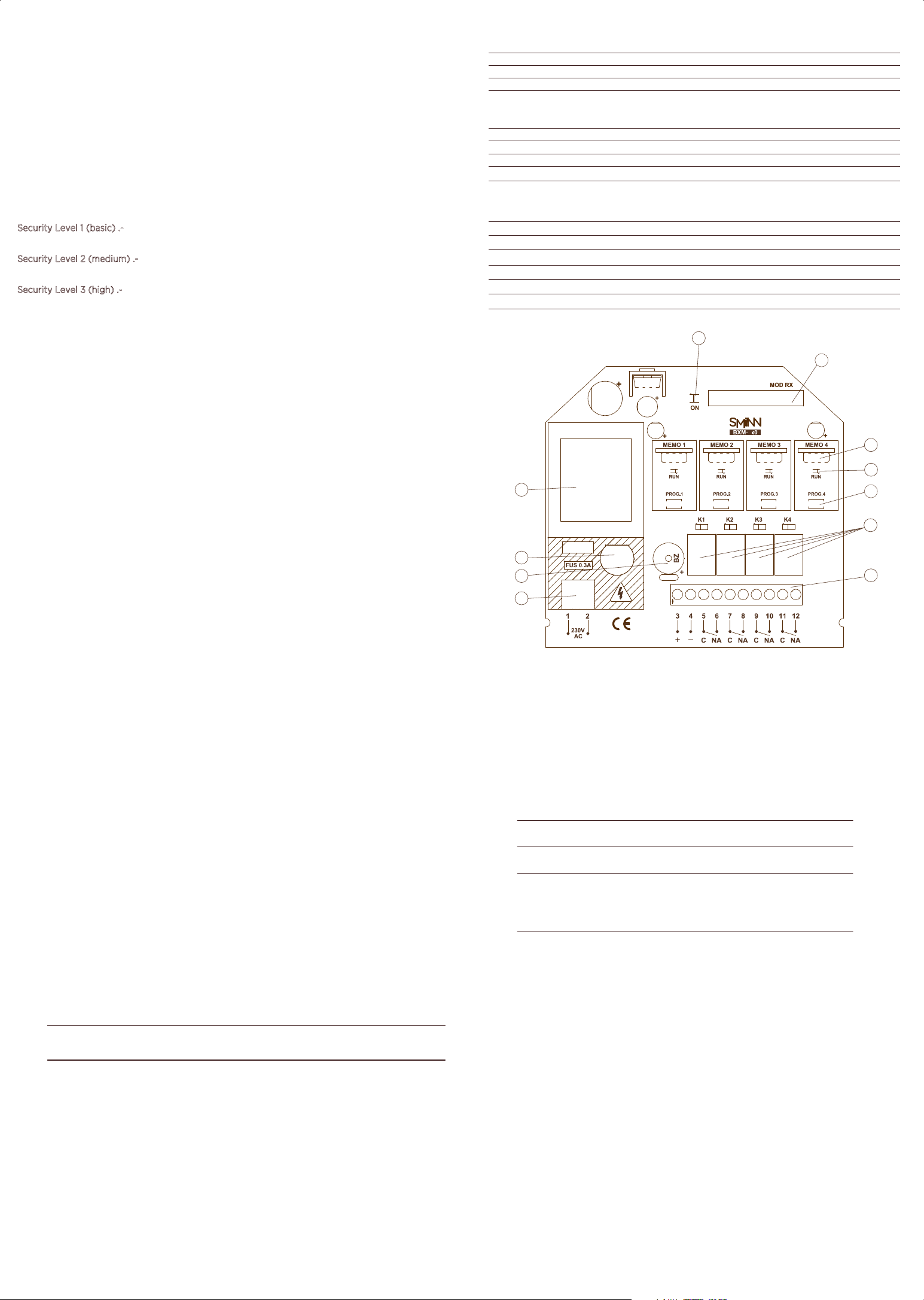
Fig.1
RADIO
COMMON
Sensibility < -115 dBm
Radio Superheterodine
Encoding High security Crypto/Rolling
Antenna Internal helicoidal
Min./Max. consumption at 12/24VDC 20mA / 80mA
Power suply 230VAC (125VAC / 24V AC/DC optional)
BOX M 240 433.92 MHz
BOX M 280 868.3 MHz
BOX M 244 433.92 MHz
BOX M 284 868.3 MHz
230 VAC
230 VAC
12/24 VAC/DC
12/24 VAC/DC
WIRING
Wiring is easy using the terminal block for three circuits.
Term. Func i nt o Note
1Power Power input V AC / 24V AC/DC230
3
4
Positiv (+)e
Negativ (-)e Power output 15VDC - 200mA MAX
7-8
9-10
11-12
N.O. Contact
5-6
Power input, power output and relays.
2
Cannal 2 Relay
N.O. Contact Cannal 3 Relay
N.O. Contact Cannal 4 Relay
N.O. Contact
Cannal 1 Relay
Power
OPERATION
When a code from a SMINN emitter is recived, the receiver checks if it is already registered in any of
4 inserted memories. If it si registered and not blocked, the relay will activate.
ERASE MEMORY
The memory can only be erased using SMINN´s programming console and knowing its PIN,
avoiding accidental or malicious erasures.
BLOCKING A CODE IN THE MEMORY
A transmitter code cannot be simply erased from the memory, but it can be blocked so it won´t
work anymore. Blocking codes in the memory can only be done using a SMINN programming
console and knowing its PIN.
TRANSMITTER RECORDING
SMINN BOX M receivers can store up to 2000 transmitters in each of the inserted memories
(depending on memory capacity 500 / 1000 / 2000). Before recording any transmitter,
we must make sure that the memories are formatted and configured correctly with an SMIINN
programming console.
Knowing the PIN it is possible to program a transmitter with the SMINNSecurity Level 1 (basic) .-
programming console that will just record itself in the receiver memory.
Only a transmitter that is already recorded can grant permission forSecurity Level 2 (medium) .-
self-recording to transmitters with the same PIN.
Recording can only be done manually and with transmitters programmedSecurity Level 3 (high) .-
with the installation PIN.
The first transmitter, which must be manually recorded, sets the working channel for the entire
memory. Other transmitters may be recorded manually or via radio, usng the same channel as the
first transmitter.
MANUAL RECORDING
To manually record transmitters using the PROG button follow these instructions:
• Power on the device and wait 5 seconds
• Press and hold the PROG button for the desired memory (PROG.1/4)
• Press and hold the desired channel button of the transmitter we want to record.
• Notice the blinking led (SCAN mode).
• Wait for the validation beeps.
• Release the transmitter button.
• Release the PROG button (PROG.1/4).
Repeat these steps for each transmitter you want to record manually.
RECORDING VIA RADIO
Depending on the memory security level it is possible to record transmitters via radio
(permission grant or invite).
(Security levels 1 or 2)Recording via permission grant
• Press and hold the first and second buttons of a recorded transmitter (MASTER transmitter).
• Wait until the transmitter led powers on (5 seconds).
• Release the transmitter buttons (The led stays powered on, LEARNING MODE).
• Make sure you are close to the receiver (1 to 10m).
• Press and hold the first button of the MASTER transmitter.
• Wait for the validation beep (Memory open for 8 seconds).
• Press and hold the working channel button of the transmitter we want to record.
• Wait for the validation beep.
• Release the button of the new transmitter.
Recording via invite
A transmitter can be invited with an already recorded transmitter (security levels 1 and 2) or using
an SMINN programming console (security level 1).
To invite a transmitter follow these instructions:
• Press and hold the first and second buttons of a recorded transmitter (MASTER transmitter).
• Press and hold the first and second buttons of a new transmitter (it must have the same PIN).
• Wait until both trnasmitter leds power on (5 seconds).
• Release the transmitters buttons (leds stay powered on, LEARNING MODE).
• Place the MASTER transmitter close to the new transmitter, with its LED touching the
SYNC AREA of the new transmitter.
• Press and hold the first button of the MASTER transmitter.
• Wait until the new transmitter blinks slowly 5 times.
• Release the button of the MASTER transmitter.
• Make sure you are close to the receiver (1 to 10m).
• Press and hold the working channel button of the transmitter we want to record.
• Wait for the validation beep.
• Release the button of the new transmitter.
TRANSMITTER REPLACEMENT
With this function it is possible to replace a transmitter code from a memory with a new one.
This functon is useful in case of loss or breakage.
This function can only be performed using the SMINN programming console and knowing the PIN
of the installation and the code of the lost transmitter.
.
BACKUP COPY
Although the device is protected against power line disturbances and electrical surges, it is
important to keep a backup of the memory card in case of breakdown or damages caused by
external circumstances such as electric storms, theft, improper handling, etc.
INSTALLATION
SMINN´s receiver is designed to be easily fixed on a wall using the suplied wall plugs and screws.
Before connecting or operating the device, the power supply switch or differential shall be
disconnected. Specialized and/or skilled personnel will do the installation, using properly protected
cable of enough gauge. Take into account that devices permanently connected to the mains need
to have an accessible connection device (i.e. a magnetothermic switch). The wiring should be done
following the instructions printed in he serigraphy of the circuit board. Make sure that the memory
is inserted and properly configured. After programming and verifying the equipment, close the
case with the supplied top.
: Reinforced concrete, metallic components and/or any other receiving device reduceNote
dramatically the radiofrequency signal, so installation close to these elements should be avoided..
1.
2.
3.
4.
5.
6.
COMPONENTS
ON Led
RUN Led
Radio Module
Radio PROG button
Memory card
Relays
7.
8.
9.
10.
11.
Terminal strip
Power connector
Fuse 0.3A
Buzzer
Transformer (Depends on model)
1
4
2
5
3
6
7
8
10
11
9
Power output +15 VDC
SMINNRECEIVERSARE EQUIPPED WITH A LED TO LET KNOW
IF THE DEVICES IS POWERED
2

This manual suits for next models

3

Other Sminn Receiver manuals

Sminn BOX M 440 User manual

Sminn

Sminn BOX M 440 User manual

Sminn BOX M GSM B User manual

Sminn

Sminn BOX M GSM B User manual

Sminn BOX S 130 B User manual

Sminn

Sminn BOX S 130 B User manual

Sminn BOX S 140 User manual

Sminn

Sminn BOX S 140 User manual

Sminn BOX S GSM A User manual

Sminn

Sminn BOX S GSM A User manual

Sminn BOX M GSM DOMO User manual

Sminn

Sminn BOX M GSM DOMO User manual

Sminn BOX M 640 User manual

Sminn

Sminn BOX M 640 User manual

Sminn BOX M GSM B User manual

Sminn

Sminn BOX M GSM B User manual

Popular Receiver manuals by other brands

Pioneer VSX-D710S operating instructions

Pioneer

Pioneer VSX-D710S operating instructions

Yamaha YBA10A owner's manual

Yamaha

Yamaha YBA10A owner's manual

TrekStor Talon S2 quick start guide

TrekStor

TrekStor Talon S2 quick start guide

PCTEL SeeGull MXflex Hardware reference manual

PCTEL

PCTEL SeeGull MXflex Hardware reference manual

FM Systems ATU-2 Instruction book

FM Systems

FM Systems ATU-2 Instruction book

Sony STR-DG710 operating instructions

Sony

Sony STR-DG710 operating instructions

Vertex Standard FTM-350R-E - SOFTWARE UPDATE PROCEDURE... Update

Vertex Standard

Vertex Standard FTM-350R-E - SOFTWARE UPDATE PROCEDURE... Update

AIS SLR350Ni user manual

AIS

AIS SLR350Ni user manual

Renishaw OMM Repair instructions

Renishaw

Renishaw OMM Repair instructions

Rohde & Schwarz R&S ESW Getting started

Rohde & Schwarz

Rohde & Schwarz R&S ESW Getting started

Chiayo NDR-3900 Operation manual

Chiayo

Chiayo NDR-3900 Operation manual

Marantz SR8300 Specification sheet

Marantz

Marantz SR8300 Specification sheet

CADDX NX-408E installation instructions

CADDX

CADDX NX-408E installation instructions

JVC KW-NT1J Service manual

JVC

JVC KW-NT1J Service manual

FlexBox T202 CX Operation manual

FlexBox

FlexBox T202 CX Operation manual

JVC RX-5030VBK Service manual

JVC

JVC RX-5030VBK Service manual

Harman Kardon AVR 1610 manual

Harman Kardon

Harman Kardon AVR 1610 manual

Pioneer PRO-100 Service manual

Pioneer

Pioneer PRO-100 Service manual

manuals.online logo
manuals.online logoBrands
  • About & Mission
  • Contact us
  • Privacy Policy
  • Terms and Conditions

Copyright 2025 Manuals.Online. All Rights Reserved.