Smithco 13-550-C User manual

PARTS & SERVICE
MANUAL
SUPER RAKE 2 WHEEL DRIVE
Model 13-551-C Bunker Rake
SUPER RAKE 3 WHEEL DRIVE
Model 13-550-C Bunker Rake
Starting Serial #1121 (2WD) November, 1999
Starting Serial #6280 (3WD)
SMITHCO PRODUCT SUPPORT
1-800-891-9435
Hwy SS and Poplar Avenue, Cameron WI 54822
E-mail: [email protected]

Introduction Service Diagrams Parts Accessories Reference
13-413 Hydraulic Sand Plow with Lift ....... 54-57
13-355 Hydraulic 3-Bank Valve ................ 58-59
13-644 Sand Plow .................................... 60-63
13-107 Infield Scarifier ............................. 64-65
13-116 Weed Cultivator............................ 66-67
13-199 Edger Kit....................................... 68-69
13-577 Scarifier Vertical Blades ............... 70-71
13-111 Drag Mat Kit .................................. 72-73
42-026 84” SS Tournament Rake ............ 74-77
42-128 72” SS Tournament Rake ............ 78-81
13-438 Rake Assembly............................ 82-83
13-606 Rake Assembly............................ 84-85
13-298 Fan Rake Attachment................... 86-87
26-007 Professional Infield Finisher ......... 88-89
26-008 Flex Action Field Finisher ............. 90-93
34-191 Box Grader ................................... 94-97
34-190 Spiker ......................................... 98-101
Reference......................................102-104
Decal List......................................................103
Quick Reference Replacement Parts ...........104
Warranty ............................... Inside Back Cover
CONTENTS
Introduction ..........................................1-3
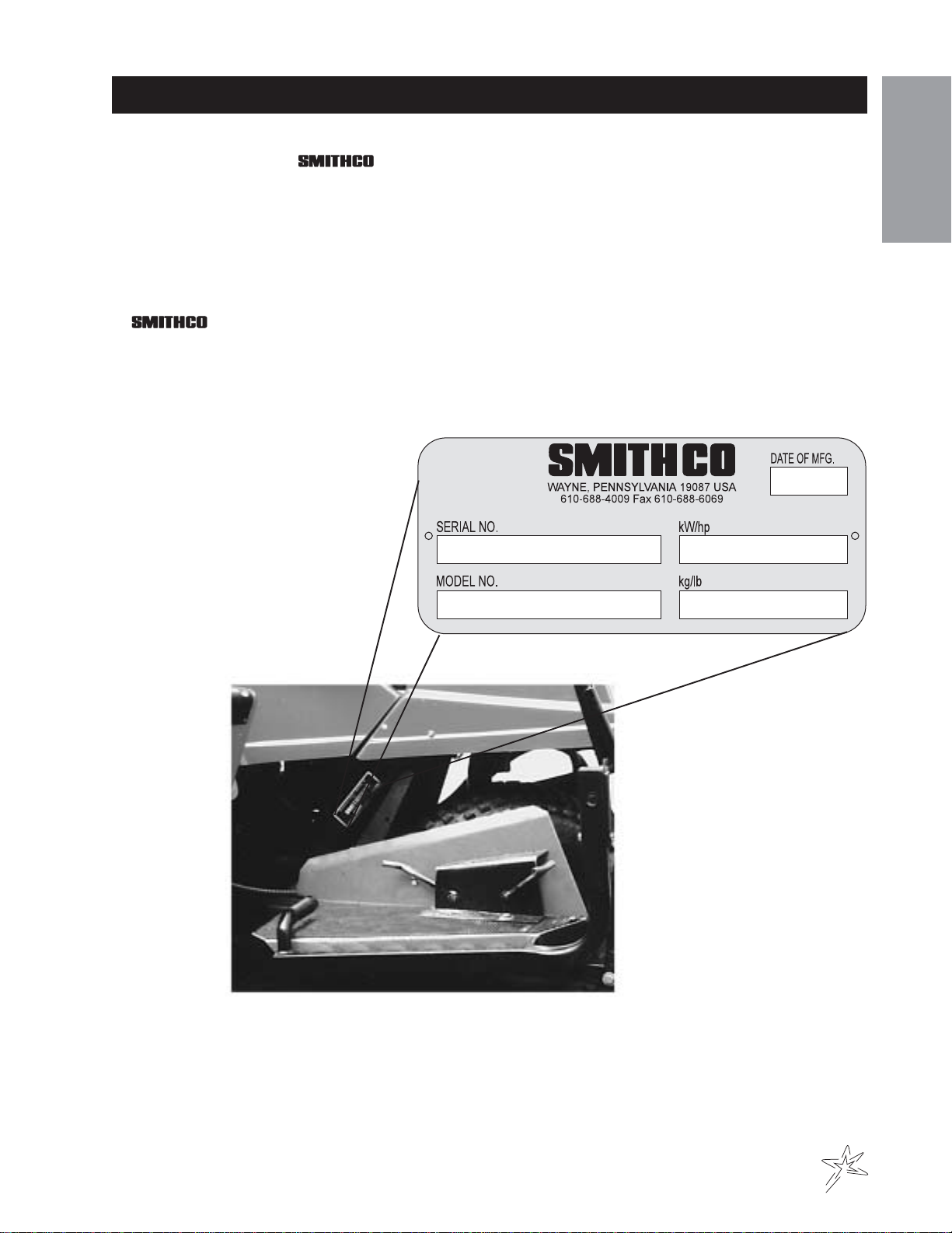
Introduction.......................................................1
Safe Practices ..................................................2
Specifications....................................................3
Optional Equipment ..........................................3
Service ................................................4-10
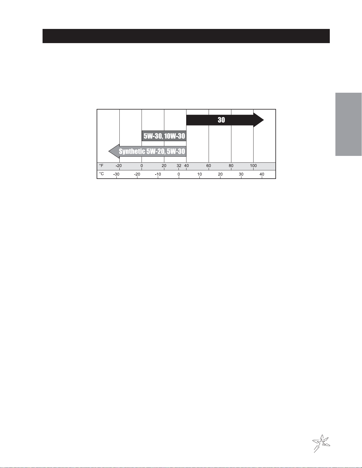
Maintenance ................................................. 4-6
Service Chart....................................................7
End User’s Service Chart .................................8
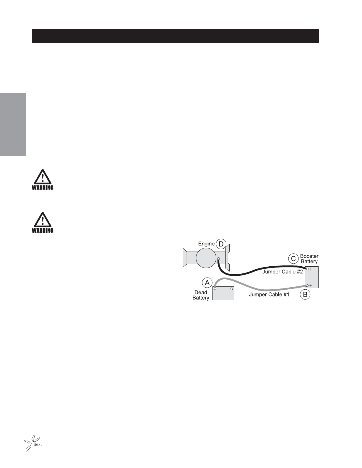
Adjustments................................................ 9-10
Storage ...........................................................10
Diagrams...........................................12-17
Wiring Diagram......................................... 12-13
Hydraulic Diagram .................................... 14-15
Wiring Schematic ....................................................16
Hydraulic Schematic ................................................17
Parts .................................................. 18-51
Main Frame .............................................. 18-21
Accelerator Linkage.................................. 22-23
Right Fender and Engine.......................... 24-25
Left Fender and Tank................................ 26-27
Console .................................................... 28-29
Two Wheel Drive Front Fork..................... 30-31
Three Wheel Drive Front Fork.................. 32-33
Engine and Pump ..................................... 34-35
Rear Axle .................................................. 36-37
Hydraulic Oil Filter .................................... 38-39
Hydraulic Oil Tank..................................... 38-39
Rear Rake Lift........................................... 40-41
On-Off Valve ............................................. 42-43
Hydraulic Valve ......................................... 44-45
13-110 Variable Pump .............................. 46-47
13-032 Front Wheel Motor (4.9 C.I.)......... 48-49
13-615 Rear Wheel Motor (7.5 C.I.) ......... 50-51
Accessories ....................................52-101
13-505 Lift Assembly ................................ 52-53
13-395 Front Mount Fan Rake ................. 54-57

1
Introduction
Informationneededwhenorderingreplacementparts:
1. ModelNumberofmachine
2. SerialNumberofmachine
3. NameandPart Number ofpart
4. Quantityof parts
INTRODUCTION
Thankyou for purchasinga product.
Readthis manualandall other manualspertainingtothe Super Rakecarefullyas theyhavesafety, operating,
assembly and maintenance instructions. Failure to do so could result in personal injury or equipment damage.
Keepmanuals in asafeplaceafter operator andmaintenancepersonnelhave readthem. Rightandleft sides are
fromtheoperator’s seat, facingforward.
All machineshavea Serial NumberandModelNumber.Both numbers areneeded whenordering
parts. The serial number plate on the Super Rake is located on the right side main frame. Refer to engine
manualforplacement of engine serialnumber.
For easy access record your Serial and Model numbers here.

2
Introduction
SAFEPRACTICES
1. It is your responsibility to read this manual and all publications associated with this machine (engine,
accessoriesand attachments).
2. Neverallow anyone tooperateorservice the machineoritsattachments without propertrainingand
instructions.Never allow minorsto operateanyequipment.
3. Learnthe proper useofthe machine, thelocationand purpose ofallthe controls andgaugesbefore you
operatethe equipment. Workingwithunfamiliar equipment canleadto accidents.
4. Wear all the necessary protective clothing and personal safety devises to protect your head, eyes, ears,
hands and feet. Operate the machine only in daylight or in good artificial light.
5. Inspect the area where the equipment will be used. Pick up all debris you can find before operating.
Bewareofoverhead obstructions andunderground obstacles. Stayalert for hiddenhazards.
6. Neveroperate equipment thatisnot in perfectworkingorder or withoutdecals,guards, shields, orother
protectivedevicesin place.
7. Never disconnect or bypass any switch.
8. Carbonmonoxide in the exhaustfumescanbe fatal wheninhaled, neveroperateamachine without proper
ventilation.
9. Fuel is highly flammable, handle with care.
10. Keep engine clean.Allowthe engine tocool before storingandalways remove theignitionkey.
11. After engine hasstarted, machine mustnotmove. Ifmovementis evident, theneutral mechanism isnot
adjustedcorrectly.Shut engine off andreadjust so themachine does notmove when inneutral position.
13. Never use yourhandsto searchforoil leaks. Hydraulicfluid under pressurecanpenetrate theskinand
cause serious injury.
14. This machine demandsyourattention.Toprevent loss ofcontrolor tipping ofthevehicle:
A. Use extra caution in backing up the vehicle. Ensure area is clear.
B. Do not stop or start suddenly on any slope.
C. Reduce speed on slopes and in sharp turns. Use caution when changing directions on slopes.
D. Stay alert for holes in the terrain and other hidden hazards.
15. Before leaving operator’sposition for anyreason:
A.Disengageall drives.
B. Lower all attachments to the ground.
C. Set park brake.
D.Shut engine off andremovetheignition key.
16. Keephands, feetandclothing away frommovingparts. Wait forallmovement to stopbeforeyou clean,
adjustor service themachine.
17. Keep the areaofoperationclear ofallbystanders.
18. Nevercarrypassengers.
19. Stopengine before makingrepairs/adjustmentsor checking/addingoilto the crankcase.
20. Use parts and materials supplied by SMITHCO only. Do not modify any function or part.
Thesemachines are intendedforprofessionalmaintenance on golfcoursesandbaseball fields. Otheruseis
forbidden.

3
Introduction
SPECIFICATIONS
WEIGHTSANDDIMENSIONS
LengthwithRake 85"(216cm)
Width with Rake 73.5"(187cm)
Height 44"(112cm)
Wheel Base 47"(119cm)
CratedWeight 990lbs (449kg)
SOUNDLEVEL(DBA)AT3200RPM
Atearlevel 84dba
At 3 ft (0.914 m) 89dba
At 30 ft (9.14 m) 74dba
ENGINE
Make BriggsandStrattonVanguard
Model# 303447
Type/Spec# 1018A2
Horsepower 16 Hp (12Kw)
Fuel Unleaded85Octane Gasoline Minimum
CoolingSystem AirCooled
LubricationSystem Pressure type
Alternator 16 amp
WHEELS&TIRE (3) 21 x 11.00 x 8 NHS 5 psi (0.35bar)
SPEED
ForwardSpeed 0 to 10 mph (0-16 kph)
ReverseSpeed 0 to 4 mph (0-6 kpk)
BATTERY(NotIncluded) Automotive type 45-12 volt
BCIGroup Size 45
ColdCrankingAmps 480
GroundTerminalPolarity Negative(-)
MaximumLength 9"(23cm)
Maximum Width 5.38"(14cm)
MaximumHeight 9"(23cm)
FLUIDCAPACITY
CrankcaseOil Approximately 1.5 quart(1.4liters) without filter
Approximately1.75 quart(1.7liters) with filter
Fuel 15.6quart (14.8 liters)
HydraulicFluid 12.9quart (12.2 liters)
GradeofHydraulic Fluid SAE 10W-40API Service SJorhigher
OPTIONALEQUIPMENT
13-413 FrontMountedSand Plow 42-128 72" StainlessSteel TournamentRake
13-644 SandPlow,AluminumBlade 13-298 Fan RakeAttachment
13-412 Hydraulic Plow (factory installed) 34-191 BoxGrader
13-505 Attachment Lift (13-551 only) 34-190 Spiker
13-395 FrontMount Fan Rake 26-007 ProfessionalInfield Finisher
13-107* InfieldScarifier 26-008 FlexAction Field Finisher
13-116* WeedCultivator 13-111 Drag Mat Kit
13-199* Edger Kit 42-550 Green StarTotal RBS System
13-438 RakeAssembly 42-503 RBS Mount forSmithco Super Rake
13-606 RakeAssembly with Lexan Blades 42-530 22-11.00 x 8 TurfTrack R/S Tire
42-026 84"StainlessSteelTournament Rake 42-531 22-11.00x 8 CustomSmoothTreadTire
* Musthave 13-505 LiftAssembly installed before installation (13-551Only).

4
Service
MAINTENANCE
Before servicing or making adjustments to machine, stop engine and remove key from ignition.
Use all procedures and parts prescribed by the manufacturer's. Read the engine manual
before operation.
Thesuggested maintenance checklistisnot offeredasa replacement forthemanufacturer’s but asasupple-
ment.You must adhereto guidelinesestablished bymanufacturerforwarranty coverage. Inadverse conditions
suchas dirt, mudorextreme temperatures, maintenanceshouldbe more frequent.
LUBRICATION
UseNo. 2 GeneralpurposeLithiumBase Grease andlubricateevery 100 hours.TheSuperRake has one
greasefitting located inbearingon steering shaft.
AIRCLEANERONENGINE
1. Unhookclipsonbothsides of cover andremovecover.
2. Carefullyslidepre-cleaneroffcartridge.
To servicepre-cleaner, washinliquid detergentandwater.Squeeze dry inaclean cloth. Saturatein
engine oil. Squeeze in clean, absorbent cloth to remove all excess oil. Replace if very dirty or damaged.
3. Removeknobandplate.Carefully remove cartridge to preventdebris from enteringcarburetor.Toservice
cartridge, clean by tapping gently on flat surface. Do not oil cartridge. Replace if very dirty or damaged.
Do not use petroleum solvents, eg., kerosene, which will cause cartridge to deteriorate. Do
not use pressurized air to clean cartridge. Pressurized air can damage cartridge.
4. Reinstallcartridge, plate andknob.
5. Reassemblepre-cleaneroncartridge.
6. Replace cover and reattach clips to body.
AIRCLEANERONFENDER
1. Removeend cap andfilter element, cleanby tapping gentlyon flat surface.Do not oilcartridge. Replace if
verydirtyor damaged.
2. Removeair clearner capandclean. Cap canbewashed in solvent,makesure its drybeforereinstalling.
HYDRAULICOIL
1. UseSAE 10W-40API ServiceSG/SH/CD/EC-11 motoroil.
2. Forproper warranty,change oil every500hoursor annually,whichever is firstandchangefilter after the
first20 hours, thenat100 hours, thenevery250hours thereafter.
3. The oil level should be 2" to 21/2" from top of fill neck when fluid is cold. Do not overfill.
4. After changing oil and/or filter, run the machine for a few minutes. Check oil level and for leaks.
5. Always use caution when filling hydraulic oil tank or checking level to keep system free of contaminants.
Checkand service morefrequentlywhen operatinginextremely cold, hotordusty conditions.
6. If natural color of fluid is now black or smells burnt, it is possible that an overheating problem exists.
7. If fluid becomes milky, water contamination may be a problem.
8. Ifeither of theaboveconditions happen, changeoiland filter immediatelyafterfluid is coolandfind cause.
Take fluid level readings when system is cold.
9. In extreme temperatures you can use straight weight oil. We recommend SAE 30WAPI Service SG when
hot(above90°F (33°C)) andSAE 10WAPIServiceSG when cold(below32°F(0°C)ambient temperature.
Use either motor oil or hydraulic oil, but do not mix.
10. Oil being added to the system must be the same as what is already in the tank. Mark tank fill area as to
which type you put in.

5
Service
MAINTENANCE
TIREPRESSURE
Caution must be used when inflating a low tire to recommended pressure. Over inflating can cause tires to ex-
plode.Tiresshould be5 psi(0.35bar). Improperinflationwill reduce tirelifeconsiderably.
ENGINEOIL
Changeand addoilaccording to chartbelow. Do notoverfill. Use ahigh quality detergentoilclassified "ForSer-
vice SE, SF, SG" SAE 30 oil. Use no special additives with recommended oils. Do not mix oil with gasoline.
SAEViscosityGrades
Starting Temperature Range Anticipated Before Next Oil Change
Aircooled engine runhotterthan automotive engines.Useof multi-viscosity oils(10W-30,etc)above 40°F
(4°C) willresultin high oilconsumption and possibleenginedamage. Checkoillevel more frequentlyif using
these types of oils.
SAE 30 oil, if used below 40° F (4° C), will result in hard starting and possible engine bore damage due to inad-
equatelubrication.
TOWING
When it is necessary to move the Super Rake without engine running, by-pass valve built into hydrostatic pump
mustbe "open"bytruning it counter-clockwise.The valveislocated on bottomleftof pump.An "open"valve
allowsfluid to pass throughthewheelsfreely.When normal,driven,operationis desired, valveshouldbe"closed
by turning it clockwise. Failure to "close" the valve with engine running means no power to wheels.
WHEELMOUNTINGPROCEDURE
1. Setparkbrake.Turn machineoffand remove key.
2. Block one of the other wheels.
3. Loosennuts slightly onwheelto be removed.
4. Jackup machine beingcarefulnotto damage undersideofmachine.
5. Removenuts,removeWheel.
5. Place new wheel on hub lining up bolt holes.
6. Torque nuts to 64-74ft/lb(87-100Nm) usingacrosspattern.Retorque after first 10hoursand every 200
hoursthereafter.
7. Lowermachine to groundandremoveblocks and jack.

6
Service
MAINTENANCE
BATTERY
Batteries normally produce explosive gases which can cause personal injury. Do not allow flames, sparks or any
ignited object to come near the battery. When charging or working near battery, always shield your eyes and
alwaysprovideproperventilation.
Batterycable should bedisconnectedbefore using "FastCharge".
Charge battery at 15 amps for 10 minutes or 7 amps for 30 minutes. Do not exceed the recommended charging
rate.If electrolyte startsboiling over,decrease charging.
Alwaysremove grounded (-)batteryclamp firstandreplace it last.Avoidhazardsby:
1. Fillingbatteriesin well-ventilated areas.
2. Weareyeprotection and rubber gloves.
3. Avoidbreathingfumes when electrolyteis added.
4. Avoidspilling or dripping electrolyte.
Battery Electrolyte is an acidic solution and should be handled with care. If electrolyte is
splashed on any part of your body, flush all contact areas immediately with liberal amounts
of water. Get medical attention immediately.
JUMPSTARTING
Use of booster battery and jumper cables. Particular care should be used when connecting a
booster battery. Use proper polarity in order to prevent sparks.
To jump start (negative groundedbattery):
1. Shield eyes.
2. Connectends of onecableto positive (+)termi-
nals of each battery, first (A) then (B).
3. Connectoneend of othercabletonegative(-)
terminalof "good" battery(C).
4. Connectother end ofcable(D) toengineblock on
unitbeingstarted (NOT tonegative(-)terminalof
battery)
To prevent damage to other electrical components on unit being started, make certain that engine is at idle
speedbeforedisconnecting jumper cables.

7
Service
Daily
As Required
100 Hours
200 Hours
250 Hours
300 Hours
400 Hours
Every 500 Hours/Yearly
¤£ Engine Oil (Change every 50 hours) CRRRRRRR
¤ Engine Oil Filter R R R R R
Engine for Leaks and Loose Parts C C C C C C
‡ Air Cleaner, Engine and Fender Mounted R C C C C R
‡ Air Cleaner Pre-Cleaner R C C C C R
Spark Plugs C R
Valve Clearance C
Idle Speed C C
Air Cooling System C C C C C C
Hoses C C C
*TirePressure CCCCCC
Visual Inspection of Tires C C C C C C
Fuel Level C C
Fuel Filter R R
Hydraulic Oil C C C C C R
† Hydraulic Oil Filter R R
Hydraulic System for Leaks and Loose Parts C C C C C C
Battery Electrolyte Level C C C C C
CleanBattery Terminals C C
§ Torque Lug Nuts C C C
Lubricate C C C C C
SERVICECHART
Before servicing or making adjustments to the machine, stop engine, set park break, block
wheels and remove key from ignition.
Follow all procedures and ONLY use parts prescribed by the manufacturer. Read the engine
manual before maintenance.
C=Check or Clean at specified intervals
R=Replace at specified intervals
* Tire pressure: 5 psi (0.35 bar)
† Replace hydraulic filters after the first 20, 100, and every 250 there after.
§ Torque tire nuts after the first 10 hours and every 200 hours there after (64 to 74 ft/lb (87-100Nm))
¤ Change Oil and Filter after first 8 hours.
£ Change oil every 25 hours when operating under heavy load or in high ambient temperatures.
‡ Clean more often under dusty conditions or when airborne debris is present , replace air cleaner parts, if very dirty.
Thesuggested maintenance checklistisnotoffered as areplacementfor the manufacturer’senginemanualbut
asa supplement.You must adheretothe guidelines established by themanufacturerfor warranty coverage.In
adverseconditions such asdirt,mudor extreme temperatures,maintenanceshould be morefrequent.

8
Service
ENDUSER’SSERVICECHART
C=Check or Clean at specified intervals
R=Replace at specified intervals
* Tire pressure: 5 psi (0.35 bar)
† Replace hydraulic filters after the first 20, 100, and every 250 there after.
§ Torque tire nuts after the first 10 hours and every 200 hours there after (64 to 74 ft/lb (87-100Nm))
¤ Change Oil and Filter after first 8 hours.
£ Change oil every 25 hours when operating under heavy load or in high ambient temperatures.
‡ Clean more often under dusty conditions or when airborne debris is present , replace air cleaner parts, if very dirty.
Daily
As Required
25 Hours
50 Hours
100 Hours
200 Hours
250 Hours
Every 500 Hours/Yearly
¤£Engine Oil (Change every50 hours)
¤ Engine Oil Filter
Engine for Leaks and Loose Parts
‡Air Cleaner (Paper Element)+A18+A18
‡Pre-Cleaner (Every 25 hours)
Spark Plugs
Valve Clearance
Idle Speed
Air Cooling System
Hoses
*Tire Pressure
Visual Inspection of Tires
Fuel Level
Fuel Filter
†Hydraulic Oil
Hydraulic System for Leaks and Loose Parts
Battery Electrolyte Level
Clean Battery Terminals
§Torque Lug Nuts
Lubricate

9
Service
ADJUSTMENTS
RAKELIFTCYLINDER
Completelylower Rake Lift.Remove cotterpin(A)and
clevis pin (B). Place attachment lift arms (C) at 1/16"
abovecross member (D)onRake Lift.Loosenjam nut (E).
Twist cylinder extension (F) so clevis pin end of cylinder exten-
sion lines up with holes in attachment lift arm. Replace clevis and
cotter pins. Tighten jam nut. Raise and lower Rake Lift to check for
properclearance.
PARKBRAKE
By turning knob on end of lever you can tighten or loosen brake a small amount. Make all adjustments on knob.
Adjusting yokes will result incable kinking.
STEERINGCHAIN
Steering sprockets (K) should be level with each other, check with straight edge.
Make any adjustments. Slide idler pulley (J) so that it is snug onto the chain.
Tighten all nuts and bolts in place.
LIFTASSEMBLY
When it is necessary to have attachment lift dig deeper or lower into
ground,relocate cylinder rodofhydraulic cylinder whichcontrols
the lift distances, into lower set of holes in attachment lift swing
arm.This new positionforces attachmentfartherdown.
WHEEL‘CREEP’ADJUSTMENT
‘Creep’ is when engine is running and hydrostatic transmission is in
neutral,but due toinadequatealignment wheels stillmove.Do the fol-
lowing procedures to stop this motion.
1. Liftup and supportmachineso all wheelsareoff the groundand
canturn freely.
2. At rear of machine, on the bottom of the hydrostatic transmission
is the shift arm (A). Loosen bolts (B).
3. With engine running move stop (C) so it moves shift arm (A) to
centerand wheel creepstops.
4. Tighten all fasteners and test by using foot pedal linkage to see
thatthe "creep" isremoved.
5. Turnengineoffandlowermachine.

10
Service
ADJUSTMENTS
SPEEDBOSS
Speed Boss allows the machine to operate at
aproper speed while rakingbunkersongolf
courses. This speed has been factory set at
anaveragespeedof3-4MPH(5-6.5kph). The
Speed Boss will only limit the speed while the
rakeis in lowereredintothe operating posi-
tion. The speed setting may be adjusted by
removingthe ball joint(A)from thelimiting
arm(B).Thenloosen jam nut(C). Turnball
joint clockwise to make the machine operate
faster or turn counter clockwise to go slower.
Tighten jam nut. Connect ball joint to limiting
arm. Check to make sure nothing is binding
and test drive to check desired speed.
When the rear rake attachment is lowered while the machine is in forward position, the
forward speed of the machine will slow drastically. Operator should be prepared for rapid
change in speed.
STORAGE
Enginesstored over 30daysneed to beprotectedor drained offuelto prevent gumfromforming in afuelsystem
oron essential carburetorparts.
1. Forengine protection, werecommenduseof Briggs andStrattonGasolineAdditive, Part Number5041,or
acomparablegasoline additive. MixAdditivewith fuel infueltankorstoragecontainer.Run engine fora
short time to circulate additive through carburetor. Engine and fuel can be store up to 24 months. Your
ServiceDealerhassingle-usepouches of GasolineAdditiveavailable.
2. Ifengine is stillwarm,drain oil fromcrankcase. Refill withfreshoil of recommendedgrade.
3. Remove spark plugs and pour about 1 oz (3ml) of engine oil into cylinders. Replace spark plugs and crank
slowly to distribute oil.
4. Cleandirt and chafffromcylinders,cylinder head fins,blowerhousing,rotating screen andmufflerarea.
5. Store in a clean and dry area, but NOTnear a stove, furnace or water heater which uses a pilot light or any
device that can create a spark.

NOTES

12
Diagrams
WIRINGDIAGRAM
Color Code Chart
Bl Blue
Br Brown
Y Yellow
Grn Green
O Orange
R Red
B Black
P Purple
W White

13
Diagrams
WIRINGDIAGRAM
REF# PART# DESCRIPTION QUANTITY
1 12-017 HourMeter 1
2 50-360 FuseHolder 1
22-071 Fuse 30AMP 1
3 13-050 Purple Wire (fuse to ammeter) 1
4 After Fire Solenoid(on engine) 1
5 Rectifier (on engine) 1
6 22-003 Ammeter 1
7 Stop Switch Terminal (on engine) 1
8 22-054 Battery Cable, Black 1
9 Battery, automotive type45-12V; 300coldcranking
AMPS minimum (53/8" wide x 9" high x 9" long) 1
10 22-055 Battery Cable,Red 1
12-031 Battery Boot 1
11 13-492 Solenoid(B& S# 807829) 1
12 13-215 StarterCable 1
13 Starter (on engine) 1
14 50-359 Oil PressureLight 1
15 8862 Coupler 1
16 22-002 Interlock Switch 1
17 13-488 Ignition Switch (B & S# 496603) 1
18 13-491 Oil Sender (on engine) (B & S# 491657) 1
19 13-641 Red Wire (ignition to hour meter) 1
22-017 GroundCablefrom Engine to SolenoidMount 1
* 13-497 WireHarness

14
Diagrams
HYDRAULICDIAGRAM
HYDRAULIC PRESSURESHYDRAULIC PRESSURES
HYDRAULIC PRESSURES
PumpDisplacement .913in.3/ rev
PumpInputSpeed (upto) 3600 RPM
Max. OperatingPressure 3500 PSI, 4500 Peek PSI
ChargePumpDisplacement .33in.3/rev
Max. Inlet Vacuum 5 in. Hg
Max. Case Pressure 25 PSI
ImplementSetting 700- 1000 PSI
ReliefValve Pressure (setat) 3600PSI
13-261HydraulicValve(2bank) 700PSI
13-355HydraulicValve(3bank) 700PSI

15
Diagrams
HYDRAULICDIAGRAM
REF# PART# DESCRIPTION QUANTITY
1 13-032 WheelMotor 1
2 13-424 Hydraulic Hose (631/4 long) 1
8840-62 FlexGuardLoom 1
3 13-425 Hydraulic Hose(701/4long) 1
8840-69 FlexGuardLoom
4 13-409 On - Off Valve 1
18-174 Elbow1/2STThread 2
18-228 HollowHexPlug 2
18-266 Elbow45° 2
5 13-587 Hydraulic Hose (16 long) 1
6 13-584 OilTank 1
13-586 FillerBreather 1
7 8810-11 Hose5/81
18-077 HoseClamp 2
8 13-616 Hydraulic Hose(29 long) 1
9 8810-36 Hose5/81
18-077 HoseClamp 2
10 13-110 HydrostaticPump 1
11 23-006 Oil Filter 1
23-031 ReplacementFilter Only
12 8917-11 Suction Hose 5/81
18-077 HoseClamp 2
13 18-184 Hydraulic Hose (29 long) 1
14 13-617 Hydrauic Hose (25 long) 1
15 13-615 Wheel Motor 2
16 13-612 HydraulicTube 2
17 23-172 Oil Cooler 1
18 13-633 Hydraulic Hose (191/2long) 2
18-264 Cap (2WD only) 2
19 18-164 Hydraulic Hose (16 long) 2
20 13-292 Hydraulic Cylinder 1
21 13-357 Hydraulic Cylinder 1
22 13-552 Hydaraulic Hose(211/4ong) 1
23 13-549 Hydraulic Hose (241/8long) 1
24 76-105 Hydraulic Hose(171/2long) 1
25 13-261 Hydraulic Valve (2 bank) 1
13-262 Valve Handle Set (2 bank) 1
13-355 HydraulicValve(3 bank)
13-484 Valve Handle Kit(3 bank)
26 60-368 Hydraulic Hose(591/4long) 1
27 13-406 Hydraulic Cylinder 1
28 13-444 Hydraulic Hose (50 long) 1

16
Diagrams
WIRINGSCHEMATIC2WHEELDRIVE

17
Diagrams
HYDRAULICSCHEMATIC2WHEELDRIVE
HYDRAULCISCHEMATIC3WHEELDRIVE

18
Parts
MAINFRAMEDRAWING
This manual suits for next models
1
Table of contents
Other Smithco Lawn Mower manuals