Smithco Spray Star 1000 Quick start guide

PARTS & SERVICE
MANUAL
Spray Star
Model 1000
PRIME MOVER
Starting Serial #100100 November, 1998
SMITHCO PRODUCT SUPPORT
1-800-891-9435
Hwy SS and Poplar Avenue, Cameron WI 54822
E-mail: [email protected]

Introduction Service Diagrams Parts Accessories Reference
CONTENTS
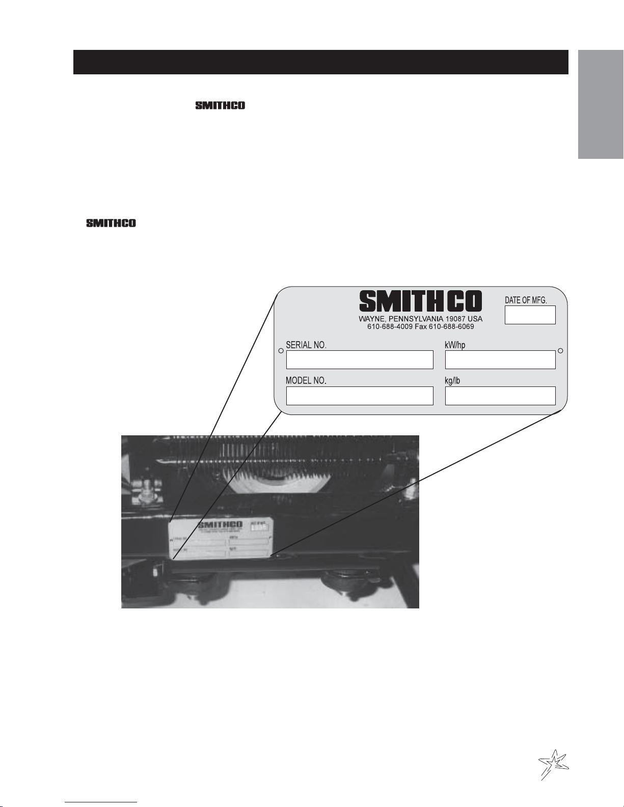
Introduction .......................................... 1-3
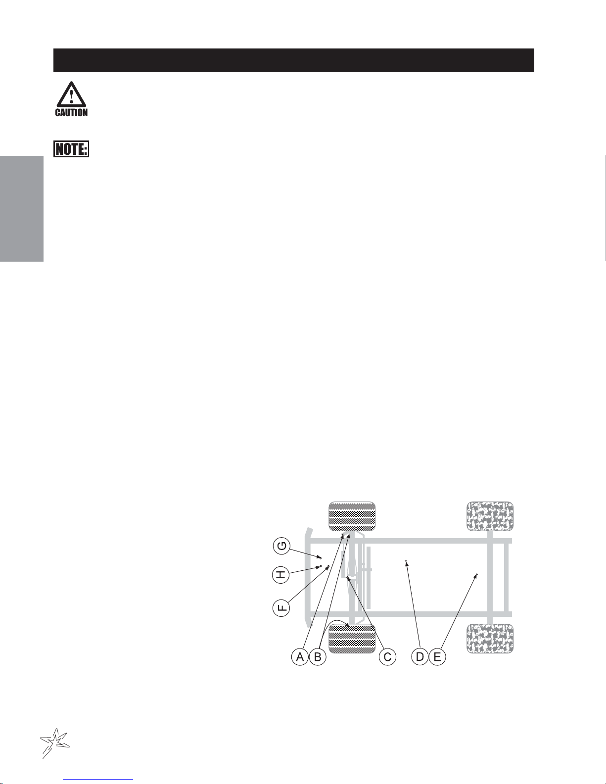
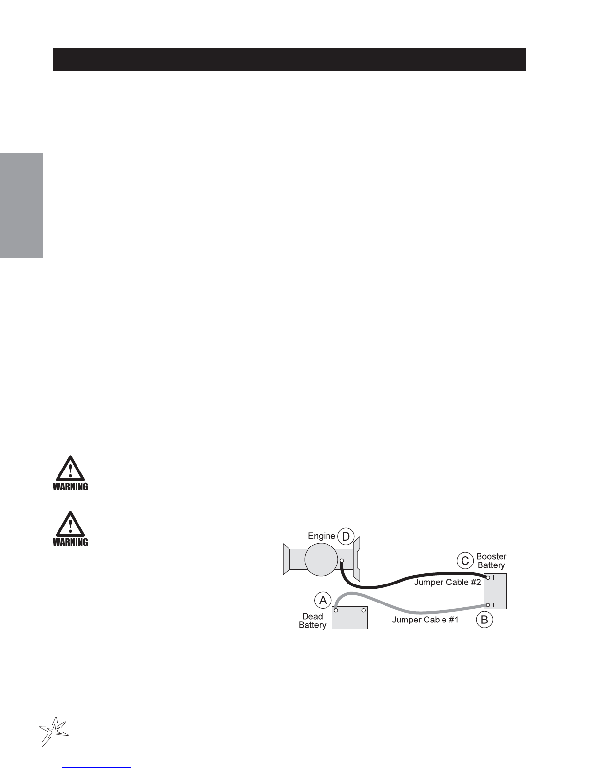
Safe Practices ..................................................................2
Specification .....................................................................3
Optional Equipment .........................................................3
Service ..................................................4-9
Maintenance ................................................................. 4-6
Service Chart ....................................................................7
End User’s Service Chart.................................................8
Adjustments .....................................................................9
Storage .............................................................................9
Diagrams...........................................10-13
Wiring Diagram ........................................................ 10-11
Hydraulic Diagram ................................................... 12-13
Parts ..................................................14-37
Body and Frame ....................................................... 14-15
Nose Cone ............................................................... 16-17
FrontAxle .................................................................. 18-19
Fuel Tank .................................................................. 20-21
Hydraulic Tank .......................................................... 20-21
Foot Pedal Linkage .................................................. 22-25
Engine,Pumps, and Exhaust ................................... 26-27
Park Brake and Rear Axle......................................... 28-29
Poly Tank .................................................................. 30-31
Turbo-Quad Agitator ................................................. 30-31
34-103 Orbitrol ......................................................... 32-33
10-117 Hydraulic Pump............................................ 34-35
16-966 Hypro®Pump................................................ 36-37
Accessories ......................................38-87
1006 Plumbing (TeeJet 834).................................... 38-41
1004 Plumbing (Manual).......................................... 42-43
1006 Controls (TeeJet 834) ..................................... 44-45
16-968 Strainer ......................................................... 44-45
15-552 Manifold Ball Valve ....................................... 46-47
15-531 Control Valve ................................................ 48-49
10-160 Stainless Steel Boom .................................. 50-53
Nozzle Assembly ...................................................... 54-55
RA Raindrop®Tips..........................................................56
XR TEEJET Tips .............................................................57
10-103 Electric Lift Kit............................................... 58-59
10-104 Hydraulic Lift Kit ........................................... 60-63
16-906 Electric Hose Reel ....................................... 64-65
16-129 Hose Reel.................................................... 66-67
10-107 Hose Reel Mounting Instructions................ 68-69
Hose Reel Plumbing................................................ 70-71
Electric Hose Reel Wiring ........................................ 72-73
Hose Reel Adjustments .................................................72
10-105 Foam Marker ................................................ 74-77
15-504 Compressor ................................................ 78-79
15-505 Motor ............................................................ 80-81
Foam Nozzle ............................................................. 82-83
10-108 Speedometer Kit .......................................... 84-85
10-106 Clear Water Wash Tank............................... 86-87
Reference.......................................... 88-90
Decal List........................................................................89
Quick Reference Replacement Parts ............................90
Limited Warranty .................................. Inside Back Cover

1
Introduction
Informationneededwhenorderingreplacement parts:
1. ModelNumber ofmachine
2. SerialNumber ofmachine
3. Nameand PartNumber ofpart
4. Quantityof parts
INTRODUCTION
Thankyoufor purchasinga product.
Read this manual and all other manuals pertaining to the Spray Star 1000 carefully as they have safety, operat-
ing, assembly and maintenance instructions. Failure to do so could result in personal injury or equipment dam-
age.
Keepmanuals inasafe placeafter operatorand maintenancepersonnel haveread them.Right andleftsides are
fromthe operator’sseat, facingforward.
All machineshave aSerial Numberand ModelNumber.Bothnumbersareneededwhen ordering
parts. The serial number plate on the Spray Star 1000 is located on the right main frame, in front of the oil tank.
Referto enginemanual forplacement ofengineserialnumber.
For easy access record your Serial and Model numbers here.

2
Introduction
SAFE PRACTICES
1. It is your responsibility to read this manual and all publications associated with this machine.
2. Neverallow anyoneto operateor servicethe machineor itsoptional equipmentwithout propertrainingand
instructions.Never allowminorstooperateanyequipment.
3. Learnthe properuseof themachine, thelocation and purposeof allthe controlsandgauges beforeyou
operatetheequipment. Workingwith unfamiliarequipment canlead to accidents.
4. Wear all the necessary protective clothing and personal safety devises to protect your head, eyes, ears,
hands and feet. Operate the machine only in daylight or in good artificial light.
5. Inspect the area where the equipment will be used. Pick up all debris you can find before operating.
Bewareof overheadobstructions andunderground obstacles.Stay alertforhiddenhazards.
6. Neveroperateequipment thatis notin perfectworking order orwithout decals,guards, shields,or other
protectivedevices inplace.
7. Never disconnect or bypass any switch.
8. Carbonmonoxide inthe exhaustfumes canbe fatalwhen inhaled,never operatea machinewithoutproper
ventilation.
9. Fuel is highly flammable, handle with care.
10. Keep engine clean.Allow the engine to cool before storing and always remove the ignition key.
11. Disengagealldrivesandset parkbrake beforestarting theengine.
12. Neveruse your handsto searchforoil leaks.Hydraulic fluid underpressure canpenetratethe skinand
cause serious injury.
13. Thismachine demandsyourattention.To preventloss ofcontrol ortippingof thevehicle:
A. Use extra caution in backing up the vehicle. Ensure area is clear.
B. Do not stop or start suddenly on any slope.
C. Reduce speed on slopes and in sharp turns. Use caution when changing directions on slopes.
D. Stay alert for holes in the terrain and other hidden hazards.
14. Beforeleaving operator’sposition:
A. Disengagealldrives.
B. Set park brake.
C. Shut engineoffand removethe ignitionkey.
D. If engine has to run to perform any maintenance keep hands, feet, clothing and all other parts of body
awayfrom movingparts.
15. Keephands, feetandclothing awayfrom movingparts. Wait forall movementto stopbeforeyou clean,
adjustorservice themachine.
16. Keepthe areaofoperation clearof allbystanders.
17. Nevercarry passengers.
18. Stopengine beforemakingrepairs/adjustments orchecking/adding oilto thecrankcase.
19. Use parts and materials supplied by only. Do not modify any function or part.
20. Use caution when booms are down as they extend out beyond the center line of the machine.
21. The tank is a confined space, take precaution.
This machine is intended for turf maintenance. Other use is forbidden.

3
Introduction
SPECIFICATIONS
WEIGHTSANDDIMENSIONS
Length 112"(285 cm)
Width 70"(178cm)
Width With Boom Open 15'(4.57 m)
Height 48"(122cm)
Wheel Base 53" (135 cm)
Weight Empty 1283lbs(582 kg)
Weight Full 2200 lbs(998 kg)
SOUNDLEVEL(DBA)
Atear level 88dba
At 3 ft (0.914 m) 84dba
At 30 ft (9.14 m) 72dba
ENGINE
Make Kohler
Model# CommandCH25S
Type / Spec# PA68620
Horsepower 25HP(18 kw)
Fuel Unleaded87 OctaneGasoline Minimum
CoolingSystem Air Cooled
LubricationSystem Full Pressure
Alternator 25 Amp
WHEELS&TIRE Front: Two 20 x 10.00 x 10 NHS Multi-Rib
Rear: Two 24 x 12.00 x 12 NHS Multi-Trac
BRAKES DynamicThrough Hydrostat
PARKBRAKE HandOperatedLever,Discs onRearAxleSpeed 0 to 3 mph (0-4.8 kph)
SPEED
Forward Speed 0-8mph (0-12.8kph)
Reverse Speed 0-3mph(0-4.8kph)
BATTERY 12 VoltAutomotive type 24F
ColdCranking Amps 700minimum
GroundTerminalPolarity Negative(-)
MaximumLength 10" (25.4 cm)
Maximum Width 7" (17.8 cm)
MaximumHeight 91/2" (24.13 cm)
FLUIDCAPACITY
CrankcaseOil See EngineManual
Fuel 5 gallon(19liters)
HydraulicFluid 5 gallon(19 liters)
Grade of Hydraulic Fluid SAE 10W-40 API Service SG Motor Oil
OPTIONALEQUIPMENT
10-101 834SpraySystem (1006) 10-106 Fresh Water Tank
10-102 ManualSpray System(1004) 10-107 HoseReel MountingKit
10-103 Electric Actuator Lift Kit 10-108 SpeedometerKit
10-104 Hydraulic Actuator Lift Kit 10-110 440 SpraySystem (1008)
10-105 FoamMarker 10-160 15' Stainless Steel Boom
16-129 HoseReel200'(61m)capacity (tobe usedwith 10-107)

4
Service
MAINTENANCE
Before servicing or making adjustments to machine, stop engine and remove key from
ignition.
Use all procedures and parts prescribed by the manufacturer's. Read the engine manual
before operation.
Thesuggestedmaintenance checklistis notoffered as areplacement forthe manufacturer’sbutas asupple-
ment.You mustadhere toguidelines establishedby manufacturerfor warrantycoverage. Inadverse conditions
suchasdirt, mudor extremetemperatures, maintenanceshouldbe morefrequent.
DAILYCHECKLIST
1. Check the engineoil level. Addas needed.DO NOT OVERFILL. Referto engineowner'smanualforoil
gradeandprocedure.
2. Tire pressure should be 20 psi (1.4 bar) maximum in the rear tires; 22 psi (1.5 bar) maximum in the front
tires.
3. Inspect the electrical system and battery cables for loose connections or frayed wiring. Replace any faulty
equipmentortighten ifloose.
4. Check hardware for loose or missing nuts, bolts, screws, etc., and tighten or replace as needed.
5. Inspect hydraulic lines for damage or leaks. Never use hands to inspect for leaks.
6. Check the hydraulic fluid level. The hydraulic fluid tank is located on the left side of the machine. The fluid
level should be 2"-2½" (5 - 6.4 cm) from the top of the fill tube when cold. Use only SAE 10W-40 API
ServiceSGMotor Oil.
7. Inspectthe steering,throttleand shiftlinkages forgood hookupsandclear travel.
8. Check controls for smooth,proper working operation. Lubricateas needed.
9. Check park brake adjustments. Adjust as required.
10. Checkanti-vibrationmounts onengine frame.
LUBRICATION
UseNo.2 Generalpurpose lithiumbase greaseandlubricate every100 hours.The SprayStar 1000 has9
greasefittings.
A. Oneon therod end ofhydraulic cylinder.
B. One on each the right and left spindles.
C. One onthe centerfront pivot.
D. Oneon thepump pivot.
E. One on the brake relay.
F. One on thepedal relay.
G. Oneon thereverse pedal.
H. Oneon theforward pedal.
EELCTRICALCONNECTIONS
Use dielectric grease on all electrical connections.

5
Service
MAINTENANCE
AIRCLEANER
1. Loosencover retainingknob andremovecover.
2. Removepre-cleaner frompaper element.
3. Checkpaperelement. Replace elementas necessary.
4. Washpre-cleaner inwarmwaterwithdetergent.Rinsepre-cleaner thoroughlyuntil alltraces ofdetergent
are eliminated. Squeeze out excess water (do not wring).Allow pre-cleaner to air dry.
5. Saturate pre-cleaner with new engine oil. Squeeze out all excess oil.
6. Reinstallpre-cleaner overpaperelement.
7. Reinstallaircleaner cover.Securecoverwithcover retainingknob.
ENGINEOIL
Changeandadd oilaccording tochart belowbased onairtemperature atthe timeof operation.Donot overfill.
Use a high quality detergent oil classified "For Service SF, SG, SH" oil. Use no special additives with recom-
mended oils. Do not mix oil with gasoline. SAEViscosityGrades
Starting Temperature Range Anticipated Before Next Oil Change
HYDRAULICOIL
1. Use SAE 10W-40 API Service SG motor oil.
2. Forproper warranty,changeoilevery500 hoursor annually, whicheverisfirst.
3. Oillevel should be2-2½" (5-6.4cm) fromtop of thefill tubewhenfluid iscold.Do notoverfill.
4. After changing oil, run the machine for a few minutes. Check oil level and for leaks.
5.
Always use extreme caution when filling hydraulic oil tank or checking level to keep system free of
contaminants. Check and service more frequently when operating in extremely cold, hot or dusty condi-
tions.
6. If the natural color of the fluid has become black or smells burnt, it is possible that an overheating problem
exists.
7. If fluid becomes milky, water contamination may be a problem.
8. Ifeither of theabove conditionshappen,change oilimmediately afterfluid iscooland findthe cause. Take
fluid level readings when the system is cold.
9. In extreme temperatures you can use straight weight oil. We recommend SAE 30W API Service SG when
hot(above 90°F(33°C)) andSAE 10WAPI ServiceSG whencold (below32°F (0°C)ambient temperature.
Use either motor oil or hydraulic oil, but do not mix.
10. Oil being added to the system must be the same as what is already in the tank. Mark the tank fill area as
to which type you put in.
DIRECTOVALVES
DirectoValvesshould be disassembled,cleaned, inspected, anda service kitinstalled annually. More often
depending on the chemicals being used and the frequency of use. In most cases this can be done without re-
movingthevalvefrom thesprayer.

6
Service
MAINTENANCE
TIREPRESSURE
Caution must be used when inflating a low tire to recommended pressure. Over inflating can cause tires to ex-
plode.Fronttires shouldbe 20psi (1.4bar)andrear tiresshould be22 psi(1.5bar).Improper inflationwill reduce
tirelife considerably.
WHEELMOUNTINGPROCEDURE
1. Setpark brake.Turnmachine offandremove key.
2. Blockwheelonoppositecorner.
3. Loosennuts slightlyonwheel tobe removed.
4. Jackup machinebeingcareful notto damageunderside ofmachine.
5. Place wheel on hub lining up bolt holes.
6. Torqueto 64-74ft/lb (87-100Nm)using across pattern. Retorqueafterfirst10hoursandevery200 hours
thereafter.
7. Lowermachine togroundandremoveblocks andjack.
BATTERY
Batteries normally produce explosive gases which can cause personal injury. Do not allow flames, sparks or any
ignited object to come near the battery. When charging or working near battery, always shield your eyes and
alwaysprovideproperventilation.
Batterycable shouldbedisconnected beforeusing “FastCharge”.
Charge battery at 15 amps for 10 minutes or 7 amps for 30 minutes. Do not exceed the recommended charging
rate.If electrolytestartsboiling over,decrease charging.
Alwaysremovegrounded (-)battery clampfirst and replaceit last.Avoid hazardsby:
1. Fillingbatteries inwell-ventilated areas.
2. Weareye protectionand rubbergloves.
3. Avoidbreathing fumeswhen electrolyteis added.
4. Avoidspilling ordripping electrolyte.
Battery Electrolyte is an acidic solution and should be handled with care. If electrolyte is
splashed on any part of your body, flush all contact areas immediately with liberal amounts
of water. Get medical attention immediately.
Use of booster battery and jumper
cables. Particular care should be
used when connecting a booster
battery. Use proper polarity in order
to prevent sparks.
TOJUMPSTART(NEGATIVEGROUNDEDBATTERY):
1. Shield eyes.
2. Connectends ofonecable topositive (+)
terminals of each battery, first (A) then (B).
3. Connectone endofother cableto negative(-) terminalof "good"battery (C).
4. Connectotherend ofcable (D)to engineblock onunitbeing started(NOT tonegative (-)terminal of
battery)
To prevent damage to other electrical components on unit being started, make certain that engine is at idle
speedbefore disconnectingjumper cables.

7
Service
SERVICECHARTKOHLERCOMMAND25HP
Before servicing or making adjustments to the machine, stop engine, set park break, block
wheels and remove key from ignition.
Follow all procedures and ONLY use parts prescribed by the manufacturer. Read the engine
manual before maintenance.
C=Check or Clean at specified intervals
R=Replace at specified intervals
* Tire pressure: 20 psi (1.4 bar) Rear. 22 psi (1.5 bar) Front.
† Replace hydraulic filter after the first 20, 100, and every 250 there after.
§ Torque tire nuts after the first 10 hours and every 200 hours there after (64 to 74 ft/lb (87-100Nm))
¤ Change Oil and Filter after first 5 hours.
‡ Clean more often under dusty conditions or when airborne debris is present , replace air cleaner parts, if very dirty.
Thesuggested maintenancechecklistis notoffered asa replacementfor themanufacturer’s enginemanualbut
asasupplement.Youmustadhere tothe guidelinesestablishedby themanufacturerfor warrantycoverage. In
adverseconditions suchasdirt, mudor extremetemperatures, maintenanceshould bemore frequent.
Daily
As Required
100 Hours
200 Hours
250 Hours
300 Hours
400 Hours
Every 500 Hours/Yearly
¤ Engine Oil w/ Filter 2.1qt. (2 l) C R R R R R
¤ Engine Oil Filter R R R
Engine for Leaks and Loose Parts C C C C C C
‡ Air Cleaner (Paper Element) C C C C C R
‡ Pre-Cleaner (Every 25 hours) C C C C C C R
Spark Plugs R C C R
Idle Speed (1200 RPM) C C
‡ Cooling System C C C C C C
Belts and Hoses C C C
* Tire Pressure C C C C C C
Visual Inspection of Tires C C C C C C
Fuel Level C C
Fuel Filter R R
Hydraulic Oil C C C C C R
†Hydraulic Oil Filter R R
Hydraulic System for Leaks and Loose Parts C C C C C C
Battery Electrolyte Level C C C C C
Clean Battery Terminals C C
§ Torque Lug Nuts C C C
Lubricate C C C C C

8
Service
ENDUSER'SSERVICECHART
C=Check or Clean at specified intervals
R=Replace at specified intervals
* Tire pressure: 20 psi (1.4 bar) Rear. 22 psi (1.5 bar) Front.
† Replace hydraulic filter after the first 20, 100, and every 250 there after.
§ Torque tire nuts after the first 10 hours and every 200 hours there after (64 to 74 ft/lb (87-100Nm))
¤ Change Oil and Filter after first 5 hours.
‡ Clean more often under dusty conditions or when airborne debris is present , replace air cleaner parts, if very dirty.
Daily
As Required
100 Hours
200 Hours
250 Hours
300 Hours
400 Hours
Every 500 Hours/Yearly
Engine Oil w/ Filter
Engine Oil Filter
Engine for Leaks and Loose Parts
Air Cleaner (Paper Element)
Pre-Cleaner (Every 25 hours)
Spark Plugs
Idle Speed
Cooling System
Belts and Hoses
Tire Pressure
Visual Inspectionof Tires
Fuel Level
Fuel Filter
Hydraulic Oil
Hydraulic Oil Filter
Hydraulic System for Leaks and Loose Parts
Battery Electrolyte Level
Clean Battery Terminals
Torque Lug Nuts
Lubricate

9
Service
ADJUSTMENTS
WHEELCREEP
"Creep" is when the engine is running and hydrostatic transmission is in neutral, but due to inadequate align-
ment, wheels still move. Do the following procedure to stop this motion.
1. Liftup andsupport machineso rear wheelsare off theground andcan turnfreely.
2. In the engine compartment, the hydrostatic transmission is on the left
side. The swash plate(D) is under the transmission and comes out
forward.Theidler arm(B)has abearing that runsin thenotch ofthe
swash plate. Loosen bolt (A).
3. Withengine running,movebearing(B) soit centerson the swash
plate(D)and 'wheelcreep' stops.
4. Tighten all fasteners and test by using foot pedal linkage to see that
'creep'isremoved.
5. Turnengine offandlower machine.
SPRAYPUMPWITHELECTRICCLUTCHBELT
Locatedtothe rearand rightof theengine.Should haveapproximately 1/2"(13mm) ofdeflectionin thecenter of
the top strand. Loosen and tighten the 5/16 -18 x 11/4set screw located on the foot of the pump mount.
PARKBRAKE
Turn knob clockwise on end of park brake to tighten. Turn it counter clockwise to loosen. If finer adjustment is
needed turn clevis on brake cable to adjust length of cable.
SPEEDCALIBRATIONNUMBERS
Thespeedcalibration numbersfor theSpray Star1006is 965.
Thespeedcalibration numbersfor SprayStar 1008is 612.
STORAGE
Iftheengine willbe outof servicefor twoormore months,use thefollowing storageprocedure.
1. Cleanthe exteriorsurfacesoftheengine.
2. Changethe oil andfilter while theengine is stillwarm fromoperation.
3. The fuel system must be completely emptied, or the gasoline must be treated with a stabilizer to prevent
deterioration.
Ifyouchoose touse astabilizer,follow manufacturersrecommendations, andaddthe correctamount for
the capacity of fuel system. Fill fuel tank with clean, fresh gasoline. Run engine for 2-3 minutes to get
stabilizedfuel intocarburetor.Closefuelshut-offvalve whenunit isbeingstoredortransported.
To empty the system, drain fuel tank and carburetor, or run engine until tank and system are empty.
4. Remove the spark plugs. Add one tablespoon of engine oil into each spark plug hole. Install plugs, but do
notconnectthe plugleads. Crankthe enginetwoor threerevolutions.
5. Store machine in a clean, dry place.

10
Diagrams
Color Code Chart
Bl Blue
Br Brown
Y Yellow
Grn Green
O Orange
R Red
B Black
P Purple
W White
WIRING DIAGRAM
Use dielectric grease on all electrical connections.

11
Diagrams
WIRING PARTS LIST
REF# PART# DESCRIPTION QUANTITY
1† 10-202 Speedometer 1
8859 Ring Terminal 3/16 2
8962 HeatShrink 2
2 8935 Buss Bar (-) 1
3 13-288 Ignition Switch(Kohler 25 099 04) 1
76-310 Key Set 1
4 34-146 Panel Mounted Circuit Breaker 1
34-145 Circuit Breaker Boot 1
5 8935 Buss Bar(+) 1
6§ SpeedometerTo (+) Buss Bar
7§ (-) Buss Bar to Hour / Voltmeter
8 42-064 Hour/ Voltmeter Combo 1
9 10-182 Hot Wire Hour / Voltmeter 1
10 50-359 OilWarningLight 1
8849-2 Black Wire 1
8860 StringConnector 1
8859 RingTerminal 3/16 1
8853 SlideOn Connector 1
8962 HeatShrink3/16 3
11 Oil Sender (Part Of Engine)
12 Ignition Module (Part Of Engine)
13 Fuel Shut-OffSolenoid (PartOf Engine)
14 Rectifier (Part Of Engine)
15 Starter (Part Of Engine)
16 10-167 RedBatteryCable 1
17 22-073 Battery (Optional) 1
18 76-327 GroundBattery Cable 1
19 10-204 Fuse Block Ground Wire 1
20 33-271 Fuse Block 1
21 10-203 Fuse Block Hot Wire 1
22 Wire With Fuse (Part Of Engine)
Fuse AGC 30
23§ (-) Buss Bar to Ignition Switch
24 77-207 Buzzer 1
8845-3.5 White Wire 1
8860 StringConnector 1
8859 RingTerminal 3/16 1
8853 SlideOn Connector 1
8962 HeatShrink 3
25§ Wire Toggle Switch To (+) Buss Bar
26 33-480 PressureSwitch 1
27 15-314 ToggleSwitch 1
15-472 Switch Boot 1
28 16-966 Hypro Pump With Electric Clutch 1
29† 10-183 WireSpeedometer Ground 1
30† 16-883 MagneticSensor 1
31† 10-209 SpeedometerWire Harness 1
10-181 Wire Harness (Includes all wire colors with *) 1
§ 10-224 ConsoleWire Harness 1
† 10-108 Speedometer Kit (optional)

12
Diagrams
HYDRAULIC DIAGRAM

13
Diagrams
HYDRAULIC DIAGRAM PARTS LIST
REF# PART# DESCRIPTION QUANTITY
1 10-143 Hydraulic Hose 2
2 10-135 Hydraulic Cylinder 1
3 10-141 Hydraulic Hose 1
4 34-103 Orbitrol Motor 1
5 10-144 Hydraulic Hose 1
6 10-142 Hydraulic Hose 1
7 18-190 Tee 1
8 34-105 Oil Cooler 1
9 10-145 Hydraulic Hose 1
10 10-116 Wheel Motor 2
11 10-123 Hydraulic Hose 4
12 8832-12 Hose 3/4 ID 1
18-222 HoseClamp 2
13 23-006 OilFilter 1
23-031 ReplacementFilter
14 8832-14 Hose3/4ID 1
18-222 HoseClamp 2
15 10-196 HydraulicHose 1
16 48-135 OilTank 1
17 10-140 HydraulicHose 2
18 10-117 HydrostaticPump 1

14
Parts
BODY & FRAME DRAWING

Parts
15
BODY&FRAMEPARTSLIST
REF# PART# DESCRIPTION QUANTITY
1 10-111 110 Gallon Poly Tank 1
2 10-193 Horizontal Boom Support 1
3 10-191 Tank Starp 2
4 14-269 Seat 1
HB-516-18-125 Bolt 5/16 - 18 x 11/44
HW-516 Washer 5/16 4
HWL-516 Lock Washer 5/16 4
HN-516-18 Nut 5/16 - 18 4
5 10-120 Park Brake Handle 1
6 48-135 Oil Tank 1
23-095 Filler Breather 1
7 10-214 Left Screen 1
HSD-14-075 Drill Screw 1/4 x 3/44
8 15-030 Steering Wheel 1
9 10-180 Left Front Fender 1
HBC-516-18-100 Carriage Bolt 5/16 - 18 x 1 4
HW-516 Washer 5/16 4
HWL-516 Lock Washer 5/16 4
HN-516-18 Nut 5/16 - 18 4
10 76-299 Black Boot 1
11 10-113 Console 1
12 10-201 Seat Panel 1
13 10-163 Forward Foot Pedal 1
14 10-164 Reverse Foot Pedal 1
15 10-137 Main Frame 1
16 11-086 Choke 1
17* 13-261 Two Bank Valve 1
13-262 Valve Handles 1
18 10-118 Kohler 25hp Engine 1
19 18-190 Tee 1
20 16-857 Tire and Wheel 2
16-857-01 Tire 20 x 10 - 10NHS 4Ply 2
16-857-02 Wheel 2
21 10-129 Front Cooler Mount 1
22 10-159 Right Front Fender 1
HBC-516-18-100 Carriage Bolt 5/16 - 18 x 1 4
HW-516 Washer 5/16 4
HWL-516 Lock Washer 5/16 4
HN-516-18 Nut 5/16 - 18 4
23 34-105 Oil Cooler 1
HB-14-20-100 Bolt 1/4 - 20 x 1 4
HWL-14 Lock Washer 1/44
HN-14-20 Nut 1/4 - 20 4
24 10-215 Right Screen 1
HSD-14-075 Drill Screw 1/4 x 3/44
25 10-130 Rear Cooler Mount 1
26 34-160 Throttle Control with Cable 1
27 10-228 Spray Boss Control 1
28 10-115 Gas Tank 1
10-220 Gas Cap 1
29 10-114 Tire and Wheel 2
10-114-01 Tire 24-12-12NHS 2
10-114-02 Wheel 2
30 10-168 Rear Fender 2
HBC-516-18-100 Carriage Bolt 5/16 - 18 x 1 8
HW-516 Washer 5/16 8
HWL-516 Lock Washer 5/16 8
HN-516-18 Nut 5/16 - 18 8
* 10-104 Hydraulic Lift Kit 1

16
Parts
NOSECONEDRAWING

Parts
17
NOSECONEPARTSLIST
REF# PART# DESCRIPTION QUANTITY
1 15-030 Steering Wheel with Cap 1
15-031 Steering Wheel Cap(Replacement Only)
2 76-294 90° Black Boot 1
3 76-293 Tilt Steering Mechanism 1
HB-516-18-150 Bolt 5/16 - 18 x 11/23
HNTL-516-18 Lock Nut 5/16 - 18 3
HWK-316-075 Woodruff Key 3/16 - 3/41
4 13-288 Key Switch (with hardware Kohler 25 099 04) 1
76-310 Key Set 1
5 34-146 Circuit Breaker 1
34-145 Circuit Breaker Boot 1
6 42-064 Hour / Voltmeter 1
7 50-359 Oil Warning Indicator Light 1
8 10-113 Console 1
9 18-202 Elbow 1
10 HB-516-18-150 Bolt 5/16 - 18 x 11/22
HB-516-18-275 Bolt 5/16 - 18 x 23/42
HNTL-516-18 Lock Nut 5/16 -18 4
11 10-163 Forward Foot Pedal 1
48-066 Pedal Pad 1
12 10-164 Reverse Pedal 1
48-132 Short Pedal Pad 1
13 10-137 Main Frame 1
14 10-200 Tower Plate 1
HSA-8-075 Tapping Screw #8 x 3/46
15 34-103 Orbitrol 1
HBM-6-1-16 Metric Bolt M6-1 x 16 4
HWLM-6 Metric Lock Washer M6 4
16 34-167 Stub Shaft 1
17 18-169 Adapter 3/8 SAE 5
18 77-207 Buzzer 1
19 15-314 Toggle Switch 1
15-472 Switch Boot 1
20* 10-202 Speedometer (Optional) 1
21 25-347 Decal, Console 1
22 50-400 Rubber Grommet 1
23 HNJ-58-18 Jam Nut 5/8 - 18 1
24 10-235 Speedometer Plug Button 1
HBM-8-1.25-40 Metric Bolt M8-1.25 x 40 1
HWLM-8 Metric Lock Washer M8 1
HNM-8-32 Metric Nut M8-32 1
25 10-236 Strong Back 1
* 10-108 Speedometer Kit 1

18
Parts
FRONTAXLEDRAWING
Other manuals for Spray Star 1000
3
Table of contents
Other Smithco Lawn Mower manuals