Smiths Pneupac babyPAC 100 User manual

Pneupac
babyPAC™100
Ventilator
ON-SITE MAINTENANCE PROCEDURE
LEVEL ONE: PERIODIC PERFORMANCE
CHECKS
0473
Smiths Medical International Ltd ©2004
PN 504-2038NUS
Issue 1 03/2005
Smiths Medical International Ltd
Bramingham Business Park
Enterprise Way
Luton LU3 4BU
England
Tel: (44) (0) 1582 430000
Fax: (44) (0) 1582 430001
Email: [email protected]
Website: www.smiths-medical.com

504-2038NUS March 2005
Page Intentionally Blank

504-2038NUS 3March 2005
Table of CONTENTS
Contents Page
SECTION 1: IMPORTANT GENERAL INFORMATION..................................................................5
a) General ............................................................................................................................................5
i) Qualified persons .......................................................................................................................5
ii) Frequency of Checking .............................................................................................................5
iii) Oxygen Safety..........................................................................................................................5
iv) Note to Service Engineers........................................................................................................5
v) MRI ...........................................................................................................................................5
vi) CE Marking..............................................................................................................................5
b) Safety Information For Medical Gas Cylinders .......................................................................6
SECTION 2: TEST SCHEDULE FOR PERIODIC CHECKING OF babyPAC 100........................7
1 Record...........................................................................................................................................7
2 Check the condition of the Input Hoses.....................................................................................7
3 Check the condition of the babyPAC.........................................................................................7
4 Check function of alarms and indicators ..................................................................................7
5 Carry out lock off leak test to input supply connections .........................................................7
6 Check the Function Selector switch...........................................................................................7
7 Check calibration of Inspiratory (TINS) and Expiratory (TEXP) Time controls ................7
8 Check calibration of PEEP & CPAP Pressure control............................................................7
9 Check calibration of Inspiratory Pressure control...................................................................7
10 Check calibration of Oxygen Concentration control on CMV with oxygen supply only .....7
11 Check calibration of Oxygen Concentration control on CPAP with oxygen and air supply7
12 Check calibration of Audible High Pressure Alarm control ...................................................7
13 Check the condition and security of mounting box, brackets, clamps and pole mounts ......7
14 Attach Service Label ...................................................................................................................7
15 Report non-critical faults to customer.......................................................................................7
16 Report critical faults to the customer ........................................................................................7
17 Obtain an acceptance signature on the Service Record Sheet where applicable. .................7
SECTION 3: PROCEDURE FOR PERIODIC CHECKING OF babyPAC 100...............................11
SECTION 4: SPARE PARTS.................................................................................................................24
a) babyPAC 100 Ventilator...........................................................................................................24
b) Special Equipment and Tools for Periodic Checking of babyPAC 100 Ventilator.............25
APPENDIX A - PRODUCT SAFETY, TRANSPORTATION AND DISPOSAL OF LITHIUM
BATTERIES .....................................................................................................................................28
List Of Figures
Figure No. Page
Figure 1: Controls and fittings of the babyPAC 100 ventilator.................................................................13
Figure 2 : Alarm Indicators........................................................................................................................14
Figure 3......................................................................................................................................................17
Figure 4......................................................................................................................................................17
Figure 5......................................................................................................................................................19
Figure 6......................................................................................................................................................21

504-2038NUS 4March 2005
©This procedure is the property of Smiths Medical International Ltd. Copyright for all purposes is
vested in Smiths Medical International Ltd. The reproduction of this procedure in whole or in part is
prohibited without express consent in writing. This procedure is offered for use only with equipment
manufactured or specifically recommended by Smiths Medical International Ltd. Rights are reserved to
make a charge for the use of this procedure or any part thereof and such right shall subsist unless and
until the same shall be expressly waived in writing. Acceptance of this document will be construed as
acceptance of these conditions.

504-2038NUS 5March 2005
SECTION ONE
SECTION 1: IMPORTANT GENERAL INFORMATION
a) General
The safety precautions given in this Section are to be seen as a guide only and are not intended to
be a comprehensive list.
i) Qualified persons
Persons servicing and repairing Pneupac ventilators and regulators must be adequately trained and
certified by the manufacturer for this task and must be fully conversant with the relevant contents of the
User's Manual supplied with the equipment. Engineers must perform service repair and testing of
equipment in line with both Health and Safety at Work regulations and their own employer’s procedures
and observe the appropriate precautions necessary when handling pressurised gases.
This Maintenance Procedure should be read fully before commencing servicing and testing.
ii) Frequency of Checking
Regular performance checking of the babyPAC 100 ventilator must be carried out with equipment
calibrated to ensure accuracy under the flow patterns generated by the ventilator.
The user should determine the frequency of periodic checks dependent upon the intensity of use.
Normally this would be not more often than once every 6 months but at least once every 2 years.
iii) Oxygen Safety
WARNING: Oil, grease or combustible lubricants, other than those approved for oxygen service,
must never be allowed to come into contact with the parts of the ventilator, oxygen
regulator, cylinder, repair tools or repair surfaces used in the servicing of this
equipment. Particular care should be taken to avoid any trace of contamination
around the oxygen inlet and outlet ports of the ventilator. Oil or grease oxidise
readily and in the presence of oxygen will burn violently.
Regulator assemblies must not be immersed in liquid at any time.
iv) Note to Service Engineers
It is the responsibility of the customer to present the equipment in a fit condition for use and
therefore servicing (if this is not your responsibility). This should enable you to quickly assess the
condition of the equipment overall and any obvious damage.
v) MRI
When the ventilator is being used/or likely to be used in an MR Environment, it is important that
only MR Compatible spares or accessories are used. This must be checked as part of the on- site
maintenance procedure.
vi) CE Marking
The babyPAC 100 ventilators described in this manual carry a CE mark to certify that they have
been manufactured to conform to the requirements of the European Medical Devices Directive
93/42/EEC. To ensure that this equipment is maintained to the requirements of the Directive only
accessories, ancillaries and spares authorised by the manufacturer should be fitted. All such parts sold
by Smiths Medical International Ltd. have /CE incorporated in their order code. Parts that are not
marked with /CE are only for sale outside the countries bound by the Directive.

504-2038NUS 6March 2005
b) Safety Information For Medical Gas Cylinders
1) The warnings on the previous page relating to the use of oxygen are particularly relevant to gas
cylinders and cylinder pressure regulators.
2) All personnel handling medical gas cylinders should have adequate knowledge of the properties
of the gas, the precautions to be taken and the correct operation of the equipment.
3) Check the cylinder for the name of the gas and the colour code to ensure that the correct
cylinder is being used.
4) Before using a cylinder check that it and its valve are in good condition. If there appears to be
any damage do not use it.
5) All cylinders are fitted with a colour coded ring on the valve stem showing when it is due for
inspection or test. Check that the cylinder is within date. If not do not use it.
6) Completely remove the disposable plastic seal from the valve. Open the valve momentarily to
blow any contamination out of the valve outlet. Ensure that the outlet is not directed towards
any person.
7) Ensure that the connecting faces on the cylinder and the regulator or fitting are clean and free
from scoring or damage.
8) The regulator or fitting can now be attached, using only a reasonable amount of effort to tighten
the connection. Never use a hammer or lever.
9) Always open the cylinder slowly.
10) Always close the cylinder valve fully before disconnecting the regulator assembly and fit a cap
or tape to the cylinder valve outlet to keep it clean.

504-2038NUS 7March 2005
SECTION TWO
SECTION 2: TEST SCHEDULE FOR PERIODIC CHECKING OF babyPAC 100
1 Record
2 Check the condition of the Input Hoses
3 Check the condition of the babyPAC
4 Check function of alarms and indicators
5 Carry out lock off leak test to input supply connections
6 Check the Function Selector switch
7 Check calibration of Inspiratory (TINS) and Expiratory (TEXP) Time controls
8 Check calibration of PEEP & CPAP Pressure control
9 Check calibration of Inspiratory Pressure control
10 Check calibration of Oxygen Concentration control on CMV with oxygen supply only
11 Check calibration of Oxygen Concentration control on CPAP with oxygen and air supply
12 Check calibration of Audible High Pressure Alarm control
13 Check the condition and security of mounting box, brackets, clamps and pole mounts
14 Attach Service Label
15 Report non-critical faults to customer
16 Report critical faults to the customer
17 Obtain an acceptance signature on the Service Record Sheet where applicable.

504-2038NUS 8March 2005
Page Intentionally Blank

504-2038NUS 9March 2005
babyPAC 100 PERFORMANCE RECORD SHEET SHEET 1 OF 2
CUSTOMER ORDER:- REPORT NO:-
UNIT LOCATION:- babyPAC 100 SERIAL NO.
INVOICE ADDRESS:-
TELEPHONE NO:- DATE OF SERVICE:-
TYPE OF SERVICE PROVIDED:-
ROUTINE CALL OUT REPAIR
TEST SCHEDULE CHECK LIST:-
1 2 3 4 5 6 7 8 9 10
11 12 13 14 15 16 17
REMARKS:-
ENGINEER’S SIGNATURE ACCEPTANCE SIGNATURE
PRINT NAME
PARTS USED FOR REPAIR
QTY DESCRIPTION PART NO PRICE
TOTAL PARTS COST:-

504-2038NUS 10 March 2005
babyPAC 100 SERVICE RECORD SHEET SERIAL NUMBER No
OXYGEN REGULATOR SERIAL No. AIR REGULATOR SERIAL No.
(1) QUALIFIED PERSON:- SIGNATURE:- DATE :
(2) CHECK CONDITION OF THE INPUT HOSES. OK / FAIL - REASON:-
(3) CHECK CONDITION OF CONTROL MODULE. OK / FAIL - REASON:-
(4) CHECK FUNCTION OF GAS SUPPLY INDICATORS & ALARMS OXYGEN OK / FAIL AIR OK / FAIL
(5) CARRY OUT LOCK OFF LEAK TEST TO GAS INPUT SUPPLY
(MAXIMUM 3 PSI IN 30 SECONDS)
OXYGEN OK / FAIL AIR OK / FAIL
(6) CHECK FUNCTION OF THE SELECTOR SWITCH
Position OFF CMV+PEEP CMV + ACTIVE CPAP IMV+CPAP
(4) CHECK ALARM FUNCTIONS
POWER SHUT DOWN OK / FAIL LOW PRESSURE DISCONNECT OK / FAIL
SINGLE GAS OPERATION OK / FAIL LOW BATTERY OK / FAIL
SUPPLY GAS FAILURE OK / FAIL HIGH PRESSURE OK / FAIL
SINGLE GAS ACKNOWLEDGE OK / FAIL CONSTANT POSITIVE PRESSURE OK / FAIL
CYCLE OK / FAIL CONSTANT POSITIVE PRESSURE ACKNOWLEDGE OK / FAIL
(7) CHECK CALIBRATION OF INSPIRATORY (TINS) AND EXPIRATORY (TEXP) CONTROLS
SETTING
ON OXYGEN ONLY @ 100% CONCENTRATION
PEEP=0, PEAK=30, VRV=80
ON AIR @ 21% CONCENTRATION
PEEP=0, PEAK=30, VRV=80
Tins Texp CMV
Tins
TOL
CMV
Tins
ACT
CMV
Texp
TOL
CMV
Texp
ACT
IMV
Texp
TOL
IMV
Texp
ACT
CMV
Tins
TOL
CMV
Tins
ACT
CMV
Texp
TOL
CMV
Texp
ACT
IMV
Texp
TOL
IMV
Texp
ACT
0.25 0.25 0.34/0.17 0.35/0.17 3.50/1.675 0.33/0.15 0.33/0.15 3.33/1.50
0.75 0.75 0.90/0.65 0.90/0.65 9.00/6.525 0.85/0.60 0.85/0.60 8.48/6.00
2.00 4.00 2.40/1.74 4.80/3.48 48.00/34.80 2.26/1.60 4.52/3.20 45.20/32.00
(8) & (9) CHECK CALIBRATION OF PRESSURE CONTROLS
PEEP /CPAP ON OXYGEN (Tins & Texp=0.5, VRV=80, PEAK=70)
Max difference PEEP to CPAP 5 cmH2O, ACTIVE PEEP TO CPAP 2 cmH2O
CALIBRATION OF INSPIRATORY PRESSURE ON
OXYGEN (Tins=2.0, VRV=80 , PEEP=0)
SETTING TOL
PEEP
ACT
PEEP
TOL ACTIVE
PEEP
ACT ACTIVE
PEEP
TOL
CPAP
ACT
CPAP
SETTING TOL ACT O2ONLY
MASTER
GAUGE
ACT O2
ONLY
PAC
GAUGE
ACT O2&
AIR
MASTER
GAUGE
ACT O2& AIR
PAC GAUGE
MIN STOP 0 0MAX 3 MAX 3 MIN STOP 12 17/7
DETENT 10 15/5 MAX 16 MAX 16 20 25/15
MAX STOP 20 25/15 MAX 26 MAX 26 DETENT 40 45/35
MAX STOP 70 75/65
OXYGEN CONCENTRATION CONTROL CALIBRATION CHECK ON 20 cmH2O BACKPRESSURE
(10) OXYGEN ONLY SUPPLY ON CMV (11) OXYGEN & AIR SUPPLY ON CPAP
SETTING TOL ACT Tins 2.0 Texp 4.0 ACT Tins 0.25 Texp 0.25 SETTING TOL ACTUAL
(20 cmH2O)
MIN STOP 50/42 MIN STOP 21% 26/21
60% 65/55 MAX STOP 70% 75/67
80% 85/75
MAX STOP 100% 100/95
(12) VARIABLE RELIEF VALVE PATIENT PRESSURE ALARM CALIBRATION CHECK
SETTING 12 20 30 40 50 60 70 80
TOLERANCE 17/7 25/15 35/25 45/35 55/45 65/55 75/65 85/75
ACTUAL

504-2038NUS 11 March 2005
SECTION THREE
SECTION 3: PROCEDURE FOR PERIODIC CHECKING OF babyPAC 100
1. Record
Record Qualified Person’s details. Record the serial number of the babyPAC 100 from the label
on the rear of the control module and the serial number(s) of the regulator body(ies).
2. Check the condition of the Input Hoses
i) From 1st January 2002 pressure hoses are date coded and should be replaced after 6 years.
Check the label on hose for replacement date.
ii) Check that there is no internal damage to the hose by feeling the rigidity of the hose and
looking for sloppiness.
iii) Ensure there is no delamination of the hose and no blisters or bubbles on the surface (check
again when the hose is pressurised).
iv) Check union ends for signs of kinking and/or damage to hose or union.
v) Replace hose if any of above is apparent.
3. Check the condition of the babyPAC 100
i) Check the Control Module looking for damage to the gauge and surround, the gas supply
indicators, the gas input and output fittings, the control knobs, the case and labels.
ii) Check that input and output connections are secure. Tighten if necessary
iii) Check that the input connector filters are clean.
iv) Check that the air intake filter is clean, unblocked and secure. Tighten if necessary.
v) If any of the filters is dirty it should be replaced.
a) First remove the relevant connector and seal from the Control Module.
b) The oxygen supply and air intake filters can be replaced by removing the O-ring
(W5520).
c) The conical filter (W9151) should now be pushed from the connector.
d) Both O-ring and filter should be replaced.
e) The air input connector has a retaining circlip holding both O-ring and disc filter.
f) Drive the filter, O-ring and circlip out of the fitting using a 5mm punch.
g) Fit new disc filter (W9158) and O-ring (W5523)
h) Insert a new special retaining circlip (W6487) pushing it down onto the face of the O-
ring using a 6mm punch.
i) Refit the connector/s with a new sealing washer (W5582/MRI).
vi) Check that the control knobs move smoothly, are not loose on spindles and do not rub on the
front panel. If spindles are bent the knob may rub on the faceplate on one side only.
vii) Check that the knob caps are affixed firmly to the knob, align with the index mark on the knob
side, and cannot be rotated, relative to the knob, during normal operation.
viii) Rotate each knob to its extreme limits to verify that the knob has not moved on its spindle.
ix) The TINS and the TEXP knobs should align exactly with both ends of the calibration marks, i.e.
at 0.25, 2.0 seconds for TINS, and 0.25, 4.0 seconds for TEXP.

504-2038NUS 12 March 2005
3. Check the condition of the babyPAC 100 (continued)
x) The O2concentration knob index mark should be equally spaced from each end of the yellow
calibration scale.
xi) PEEP/CPAP and Inspiratory controls should align closely with the calibration marks at the
extreme positions but should also just enter the red segment of the calibration mark when each
knob initially comes into contact with the rumble strip at their intermediate positions.
xii) The Pressure Alarm control knob should align with the extremes of the calibration marks.
xiii) The dot on the Function Selector switch should align with the marks on the panel at each
selection and there should be no intermediate positions.
xiv) If the index mark on any knob side or the cap end is misaligned it should be corrected before
further calibration checks are carried out.
xv) To relocate the knob position for controls (except the Pressure Alarm and Function Selector)
first remove the end cap from the knob.
xvi) Turn the knob nearly to the end stop at which it is at its maximum height above the panel
(timer controls at minimum time, pressure controls at maximum pressure and O2
Concentration control at 100%) in order to minimise possible needle/seat contact during knob
removal.
xvii) Using an appropriate collet spanner (e.g. 500-82073) and supporting the knob by hand in
order to minimise any axial thrust on the spindle, release the knob from the spindle.
xviii) Set the TINS and TEXP spindles against their 0.25 second stops and replace the knobs onto the
spindles.
xix) Maintaining a gap to the face panel of 0.4/0.5 mm and correct alignment at the 0.25 second
calibration, gently retighten the knob collet using only a rotary action. Check that the knobs
align with the scale at both ends.
xx) Rotate the knobs until they are just backed-off from the maximum time stop and then tighten
the collet screw as tightly as possible with recommended tool (500-82037) while
simultaneously supporting the knob by hand to minimise the force applied to the spindle.
xxi) Repeat the above procedure for the O2Concentration control but using a minimum gap to the
panel of 0.4/0.5mm and making the initial settings at the minimum concentration calibration.
Check that the knob is located as in x) above. Finally tighten just short of the maximum
calibration position.
xxii) Finally repeat the above procedure for the PEEP/CPAP and Inspiratory Pressure controls but
making the initial settings at the minimum pressure calibration. Check that the knobs are
located as in xi) above and then finally tighten just short of the maximum pressure settings.
xxiii) With the knobs in the final re-tightening position refit the knob cap ensuring the line on the
cap aligns with the line on the side.
xxiv) The Pressure Alarm and Function Selector switch knobs have a fixed location but the cap can
be relocated on the front of the knob if the indication is incorrect.
xxv) If the caps on the above knobs have been removed for relocation or can be rotated, relative to
the knob, during normal operation they should be secured to the knob with a very small drop
of adhesive (DS354 C10/Loctite Prism 460).
xxvi) Check that the gauge surround is secure, the front panel label is secure and not damaged (e.g.
punctured) and the silencing button is undamaged.
xxvii) Check that the gauge is in the correct vertical position and has not rotated in the shroud.
504-2038NUS 13 March 2005
3. Check the condition of the babyPAC 100 (continued)
xxviii) Remove the existing battery and check when battery was last changed. If 12 months or
more has elapsed, insert a new battery of the correct type (part no. W269-023). If service
interval is less than 12 months, mark the battery, or service log for the ventilator, with the date
of replacement.
xxix) Replace any damaged labels.
xxx) Check that any accessories or spares added are MR Compatible.
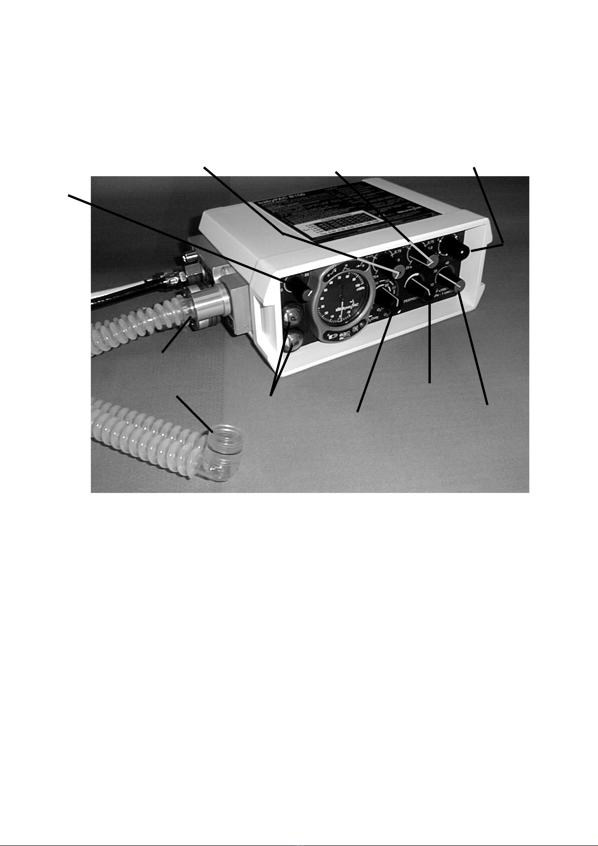
Figure 1: Controls and fittings of the babyPAC 100 ventilator
Supply gas failure
visual alarm Oxygen
concentration
PEEP/CPAP
Function Selector switchExpiratory time TEXP
Inspiratory time TINS
High
inflation
pressure
alarm
Connector
Y-piece
Patient Inspiratory
Pressure

504-2038NUS 14 March 2005
Figure 2 : Alarm Indicators
4. Check function of alarms and indicators
(refer to Figure 2)
i) Set the Function Selector to ‘0’.
ii) Without a gas supply connected to the ventilator, select CMV + PEEP.
iii) The gas supply indicators will stay red but the alarm LEDs will flash in sequence, starting
bottom left and rotating in a clockwise direction. After all 6 LEDs have flashed a Medium
Priority alarm will sound and continue for 1 minute. If the ventilator is still left switched on
the alarm system will shut down.
iv) With the air and oxygen input hoses connected to the ventilator, connect the hose probes to
appropriate gas supplies (minimum requirement 20L/min at 305kPa ≈ 3 bar).
v) Connect a C0.5 R100 ISO Test Lung (500 - 84250) to the Patient Connection Port of the
Patient Circuit.
vi) Turn on the air supply and the lower supply gas failure visual alarm should change from red to
quartered white and black. Repeat for the oxygen supply; the upper alarm turning from red to
white.
vii) Set both the Oxygen Concentration and the PEEP/CPAP controls to minimum.
viii) Select CMV + PEEP on the Function Selector switch. The ventilator should now begin to
cycle and the alarm LEDs will go through the test sequence described in iii). The yellow
‘silenced’ LED (bottom right) should flash but no sound should be generated for 60 seconds.
The ‘cycle’ LED should flash for 1/10 second each time the pressure rises through 10
x100Pa (10 cmH2O).
ix) Turn off the air supply. As the supply depletes, the air supply gas visual alarm should change
to red. A medium priority electronic audible alarm giving a burst of three pulses 6 times a
minute should then sound for 60 seconds to indicate a supply failure and the ‘single gas
operation’ LED should illuminate in bursts of three flashes every 30 seconds.
Cycle
High inflation
pressure/ Constant
positive pressure
Low battery
Single gas operation/
Supply gas failure
Low inflation pressure
(disconnect)
Silence
button
Electronic alarm
silenced/muted

504-2038NUS 15 March 2005
4. Check function of alarms and indicators (continued)
(refer to Figure 2)
When the air supply is depleted the ventilator may pause but will then continue to operate on the
oxygen supply. If the ventilator fails to change over it should be returned to the manufacturer
for repair.
x) Depress the Silence/Mute button and the electronic audible alarm should silence for 60
seconds. After this 60-second period has elapsed, depress the button again and the audible
alarm will now remain muted, the second depression being interpreted as an
acknowledgement by the operator that single gas operation has been recognised. The ‘single
gas operation’ LED will continue to operate to indicate this mode.
xi) Set the Oxygen Concentration control to its maximum (100%) position.
xii) Turn off the oxygen supply.
xiii) Repeat step ix) above but this time the oxygen supply gas failure visual alarm should change
to red and the audible alarms should sound. After 60 seconds the alarm system should switch
itself off in order to protect the battery if the ventilator is left in a potential alarm condition
after use.
xiv) Select ‘0’.
xv) Turn on the oxygen supply only.
xvi) Select CMV + PEEP. No audible alarm should sound as the condition of one gas supply only
at start up is taken as an intended condition. The ‘single gas operation’ LED will, however,
continue to flash as a reminder that this mode of operation has been selected.
xvii) Select ‘0’.
xviii) Remove the battery and insert a standard 1.5v AA size battery in its place. Select
CMV+PEEP. The alarms should show as in viii) above but the low battery light should also
flash.
xix) Select ‘0’. Refit the original battery. Turn off the oxygen supply and disconnect from the
supply connector.
5. Carry out lock off leak test to input supply connections
i) Connect an isolation valve with a calibrated 0-700 kPa (0-100 psi) gauge to the oxygen
supply.
ii) Connect the oxygen supply hose to the isolation valve.
iii) Check that the isolation valve is open.
iv) Turn on the gas supply and note the pressure indicated.
v) Close the isolation valve and check that the pressure retained between valve and the ventilator
does not drop by more than 20 kPa (3 psi) in 30 seconds.
vi) If the pressure drops faster check that there is no leakage at the connections on the isolation
valve, supply hose and ventilator. Also check that there is no leakage of gas from the air hose
probe indicating a cross leak. No external leak would indicate an internal leak and the
ventilator should be returned to the manufacturer for repair.
vii) Disconnect the oxygen supply and open the isolation valve to purge the hose.
viii) Repeat the test above for the air supply connection.

504-2038NUS 16 March 2005
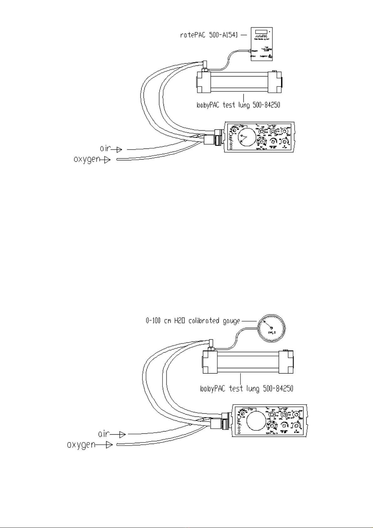
6. Check the Function Selector switch
(refer to figure 1)
i) Connect a ratePAC (510-A1541) to the Test Lung.
ii) Connect the oxygen probe of the ventilator directly to the oxygen supply.
iii) Turn on the oxygen supply. There should be no alarms.
iv) Select each function in turn and check the following:
a) 0 - No output from the ventilator nor the alarms.
b) CMV+PEEP or CMV+ACTIVE PEEP - Pulsed output, times controlled by TINS and
TEXP controls and pressures controlled by Inspiratory Pressure and PEEP/CPAP
controls. The ‘cycle’ LED should flash for 1/10 second each time the pressure rises
through 10 x100Pa (10 cmH2O). The ‘single gas operation’ LED should flash to indicate
single gas selection.
c) CPAP - Constant flow output from ventilator, not cycled. Pressure controlled by
PEEP/CPAP control. No electronic alarms function during CPAP.
d) IMV+CPAP - Pulsed output as CMV, but CPAP during a longer TEXP time. No
electronic alarms function during IMV + CPAP.
v) Check for positive switching, i.e. that there are no indeterminate mid-positions where the
function is not clearly indicated by the marking on the panel label.
vi) Turn to ‘0’. The ventilator should stop functioning and all alarms should cease.
vii) Turn off the oxygen supply.
7. Check calibration of Inspiratory (TINS) and Expiratory (TEXP) Time controls
7a. On Oxygen Only
(refer to Figure 3)
i) Set Oxygen Concentration control to 100% (maximum)
ii) Set PEEP/CPAP pressure control to minimum.
iii) Set Inspiratory Pressure control to 30 x100Pa (30 cmH2O).
iv) Set Pressure Alarm to 80 x100Pa (80 cmH2O) maximum.
v) Turn on oxygen supply.
vi) Select CMV + PEEP. The ‘single gas operation’ LED should flash every 30 seconds and the
‘cycle’ LED should flash for 1/10 second each time the pressure rises through 10 x100Pa (10
cmH2O).
vii) Confirm inspiratory pressure on the Patient Pressure Manometer.
viii) Select each of the settings specified on section 12a of the Service Record Sheet.
ix) Record the actual time for each TINS and TEXP setting in the appropriate boxes.
x) Select IMV + CPAP and record the TEXP time in the appropriate box. (The electronic alarm
system does not operate during the IMV mode.)
xi) Select ‘0’.
504-2038NUS 17 March 2005
Figure 3
7b. On Oxygen and Air
(refer to Figure 3)
i) With oxygen still connected, reconnect the air supply.
ii) Set the Oxygen Concentration control to 21% (minimum).
iii) Turn on the air supply. The ‘single gas operation’ LED should not flash.
iv) Select CMV + PEEP. After the initial 60 seconds only the ‘cycle’ LED should be flashing.
v) Select each of the settings specified on section 12b of Service Record Sheet.
vi) Repeat 12a vii), viii) and ix) above.
vii) Select ‘0’. All alarms should cease.
viii) Turn off and disconnect the air supply.
ix) Disconnect the ratePAC.
Figure 4

504-2038NUS 18 March 2005
8. Check calibration of PEEP & CPAP Pressure control
(refer to Figure 4)
i) Connect a calibrated 0-100 x100Pa (0-100 cmH2O) pressure gauge (e.g. 500-82802/2) to the
Test Lung.
ii) Set TINS and TEXP at 0.5 secs
iii) Set Pressure Alarm at 80 x100Pa (80 cmH2O).
iv) Set Inspiratory Pressure at 70 x100Pa (70 cmH2O).
v) Select CMV+PEEP. The ‘single gas operation’ LED should flash every 30 seconds and the
‘cycle’ LED should flash for 1/10 second each time the pressure rises through 10 x100Pa (10
cmH2O).
vi) Check & record minimum, detent & maximum PEEP on both the calibrated gauge and the
Patient Pressure Manometer. When the PEEP level is greater than 10 x100kPa (10 cmH2O)
for longer than 8 seconds, the ‘cycle’ LED will not indicate but after 8 seconds the Constant
Positive Inflation Pressure alarm should activate (see Figure 2). The ‘high inflation pressure’
LED should flash 2 times per second and a high priority audible alarm should sound,
consisting of two bursts of five pulses at a rate of 6 times per minute.
vii) Depress the ‘silence’ button and the electronic audible alarm should silence for 60 seconds.
After this 60-second period has elapsed, depress the button again and the audible alarm should
now remain muted. The ‘single gas operation’ LED will continue to indicate.
viii) Select CMV+ACTIVE PEEP.
ix) Check & record minimum, detent & maximum ACTIVE PEEP on both calibrated gauge and
Patient Pressure Manometer.
x) Select CPAP. During CPAP no alarm should operate.
xi) Check & record minimum, detent and maximum CPAP on both the calibrated gauge and the
Patient Pressure Manometer.
xii) The difference between the calibrated gauge and the Patient Pressure Manometer should be no
more than 2 x100Pa (2 cmH2O).
xiii) Select ‘0’.
9. Check calibration of Inspiratory Pressure control
(refer to Figure 4)
i) Select CMV+ PEEP. The ‘single gas operation’ LED should flash and the ‘cycle’ LED should
flash each cycle.
ii) Set TINS at 2.0 seconds.
iii) Set Pressure Alarm at 80 x100Pa (80 cmH2O).
iv) Set PEEP/CPAP control to minimum.
v) Set the Inspiratory Pressure successively to minimum, 20 x100Pa (20 cmH2O), detent and
maximum inspiratory pressures and record the readings on both the calibrated gauge and the
Patient Pressure Manometer at each setting.
vi) Select ‘0’.
vii) Reconnect the air supply to the ventilator.
viii) Turn on the air supply.
ix) Select CMV + PEEP. The ‘cycle’ LED should flash.
x) Repeat v) above.

504-2038NUS 19 March 2005
9. Check calibration of Inspiratory Pressure control (continued)
xi) Disconnect one limb of the Patient Circuit.
xii) After 8 seconds the ‘low inflation pressure’ alarm should flash and sound. The LED should
flash 30 times a minute and the medium priority audible alarm should sound.
xiii) Select ‘0’.
xiv) Turn off and disconnect the air supply.
xv) Disconnect Patient Circuit, Test Lung and pressure gauge from the ventilator.
10. Check calibration of Oxygen Concentration control on CMV with oxygen supply only
(refer to Figure 8)
i) Fit a 22mm hose at least 300mm long, a Backpressure Device (500-A82803) and an Oxygen
Monitor (POM 602) onto the output connector of the Control Module.
ii) Connect a 22mm hose, at least 900mm long, to the outlet of the Oxygen Monitor to ensure
that atmospheric air cannot reach the sensor during the expiratory phase
iii) Select CMV + PEEP. Both the ‘single gas operation’ LED and the ‘cycle’ LED should
indicate.
iv) Set a backpressure of 20 x100Pa (20 cmH2O) using the Backpressure Device.
v) Set TINS to 2.0 seconds and TEXP to 4.0 seconds.
vi) Record the actual oxygen concentrations at the various settings indicated by section 15 of the
Service Record Sheet.
vii) Set TINS to 0.25 seconds and TEXP to 0.25 seconds.
viii) Repeat vi) above.
Figure 5
11. Check calibration of Oxygen Concentration control on CPAP with oxygen and air supply
(refer to Figure 8)
i) Reconnect and turn on the air supply.
ii) Select CPAP. There should be no audible or visual electronic alarms.
iii) Set a backpressure of 20 x100Pa (20 cmH2O) using the Backpressure Device.
iv) Check and record oxygen concentrations at the various settings indicated by section 16 of
Service Record Sheet.
v) Select ‘O’. Turn off and disconnect the air supply.
vi) Remove the Oxygen Monitor and 900mm hose.
900mm 22mm hose W7483
300mm 22mm hose W6861Backpressure Device 500A82803
Oxygen Monitor POM60

504-2038NUS 20 March 2005
Table of contents
Popular Fan manuals by other brands


Vent-Axia
Vent-Axia VASF100B Installation and wiring instructions

Reznor
Reznor HURACAN H25 Series Installation, operation and maintenance

Americ Corporation
Americ Corporation VAF-3000P owner's manual

Renson
Renson Cube manual

IXL
IXL Ventflo 10334 Installation instructions and user guide

Sunbeam
Sunbeam FA7500 Instruction booklet