Smokin Solutions Eco-Quartz User manual

16
Fault Finding
ZN1020 Issue 2
Copyright © 2006 Sabring Ltd
Fault Reason Check Repair
The lights and
heater do not
work
ower is not
connected
Mains plug is not
connected
Reconnect plug
Fuse in plug is
blown
Replace fuse (13A)
The heater
does not switch
on
Tube is faulty Tube is correctly
seated in the hold-
ers
Check and replace
tube if necessary
Ambient
temperature is
above 20°C
Heater will only
turn on below 20°C
Heater and/or
lights do not
switch
automatically
Manual override
has been set
Switch back to Auto
using remote
control
The lights do
not switch on
Light level is too
high (daylight)
Lights will only turn
on at low light lev-
els
A light is shining
on the sensor
Sensor position
and other sources
of light
Reposition sensor if
necessary
The lights do
not switch off
in daylight
Sensor is covered
or in a shaded
place
Sensor position Reposition sensor if
necessary
Manual override
has been set
Switch back to Auto
using remote
control
Manual override
has been set
Switch back to Auto
using remote
control
Remote Control
does not work
Light on remote
does NOT come
on
Battery not fitted
or exhausted
Fit or replace bat-
tery
Light on remote
does come on
Button press too
short
ress button for a
longer time.
Eco-Quartz Heater
Instruction Manual
Sabring Ltd
Unit 4, Moderna Business ark,
Mytholmroyd, HX7 5QQ
West Yorkshire, England
Tel: +44 (0) 1422 886888
Fax: +44 (0) 1422 886444
www.smokinsolutions.com
2
CONTENTS
Unpacking age 3
lug Fitting age 5
Heater Assembly age 5
Installation age 6
Wiring age 7
Adjustment age 8
Operation age 9
Remote Control age 10
Maintenance & Cleaning age 11
Spares List age 13
rogramming age 14
Specification age 15
Fault Finding age 16
Please ensure
that you have read this instruction booklet
BEFORE attempting to install or operate
this heating unit
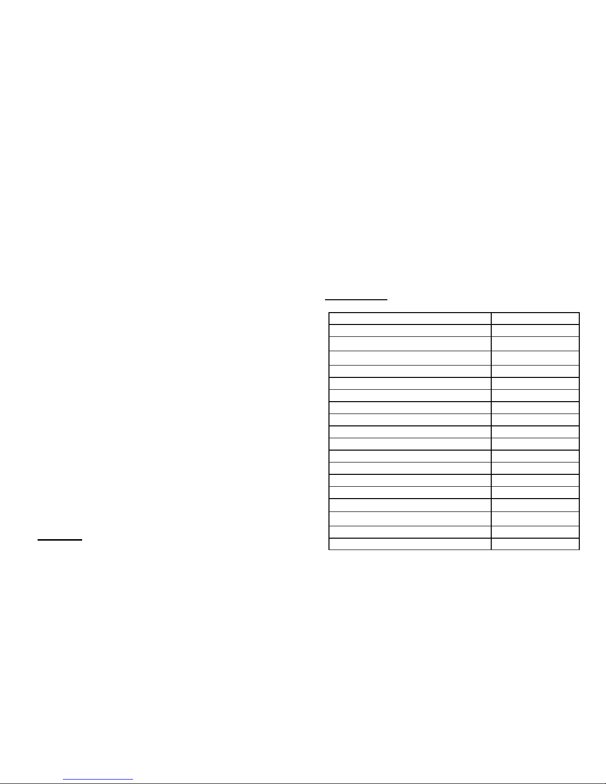
15
Voltage 230V ac
Total Current 6A
Heater Maximum ower 1300W
Lights Maximum ower (each) 50W
Total ower 1400W
Minimum mounting height from the floor 2.5m
Minimum distance from the ceiling 0.5m
Size (overall) (W x H x D) 602 x 320 x 220mm
Weight 8Kg
Lampholder (heater) R7S
Lampholder (lights) GU10
Ingress rotection I 54
Lights On Level 70 LUX
Lights Off Level 500 LUX
Lower Temperature Switching oint 15°C
Upper Temperature Switching oint 20°C
Remote Control Frequency 433MHz
On Time (Minimum) 4.5 minutes
Heater Maximum ower (Eco Mode) 975W
• Carefully replace the lid, ensuring that the ensure that the wa-
terproof seal is still fitted in its groove and that the IR is
pointing in the correct direction
• Fit and tighten the screws.
To link more than one heater to a remote control follow procedure
B for each heater in turn.. Similarly more that one remote control
can be programmed to a heater.
Specification
14
rogramming
! DANGER !
! MAINS VOLTAGE IS RESENT ON MANY !
! COM ONENTS ON THE !
! HEATER CONTROL CIRCUIT BOARD !
The heater remote control handset supplied is already programmed to
operate the heater.
Should reprogramming become necessary this should only be
carried out by a suitably qualified electrician in accordance
with the current IEEE safety regulations, and by following the
procedure below
• Disconnect the power.
• Remove the 4 screws securing the lid to the control box
underneath the heater and remove the lid. Be careful as the IR
on the lid is connected to the circuit board in the box.
• Reconnect the power, a “Di, Di, Di” sound will be heard as the
circuit starts up.
• ress and hold down the “Learn key” on the circuit board, using
an insulated screwdriver for more than 6 seconds, the circuit
board gives out continuous long-sound “Dee, Dee, Dee” and
then a short-sound “Di, Di, Di,…”
• When the sound has stopped release the “Learn key”.
B: To link a new remote to the heater
• ress and hold down the learn “key” for about 3 seconds until
the first sound is heard. Release the Learn Key and the circuit
board will continuously sound “Dee, Dee, Dee…”
• Remove the battery cover on the remote control handset and
press the left hand button, the circuit board will sound “Di, Di,
Di”.
• The remote transmitter is now linked to the heater.
A: To reset the system and remove ALL remote control devices
3
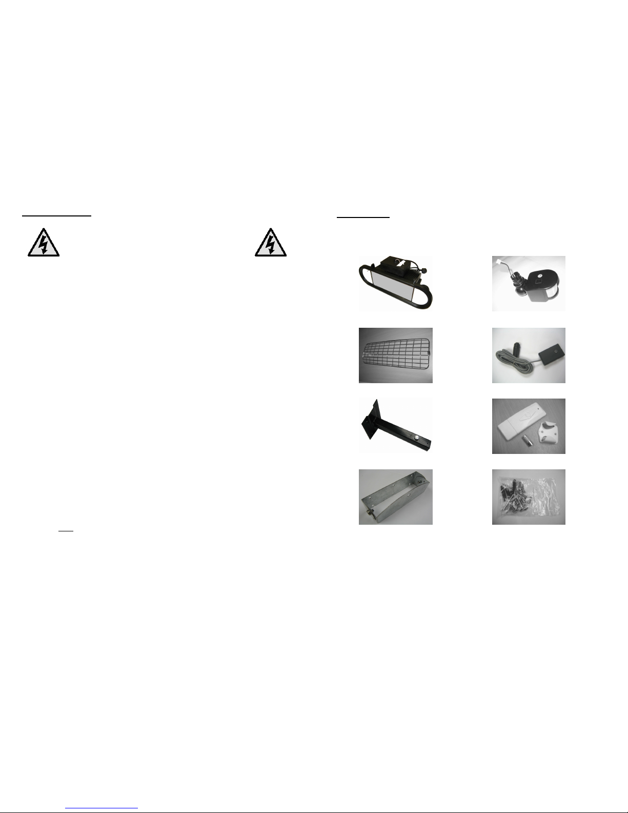
Unpacking
lease unpack and check the contents of the box before proceeding
with the installation. The box should contain the following parts:
If any of the above parts are missing please contact us, before
proceeding, at the address shown on the front cover.
Heater Unit IR
Wire Grille Temperature/Light Sensor
Wall Mounting Bracket Remote Control Handset.
Heater Unit Bracket Hardware ack
4
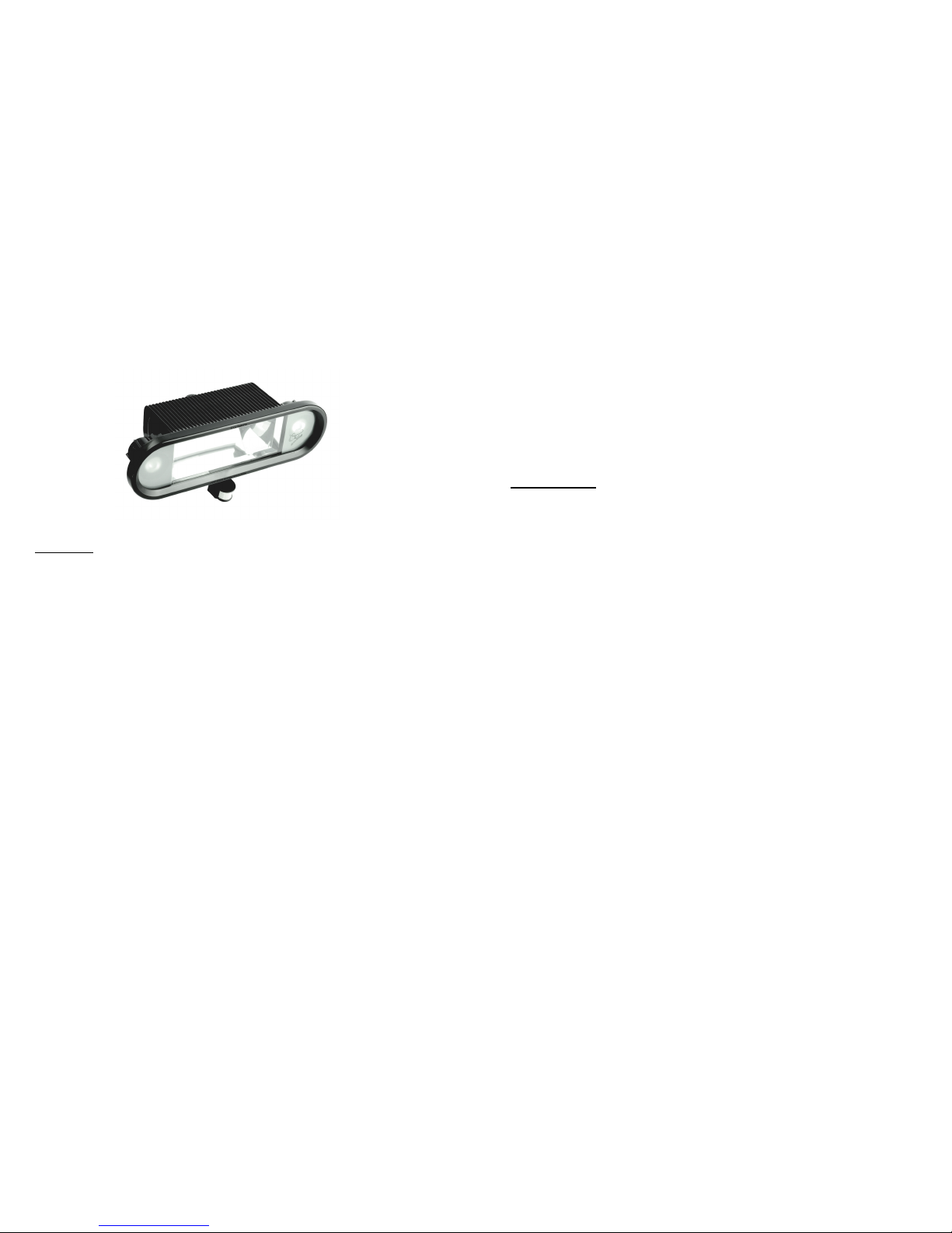
The Eco-Quartz heater warms people and not the air by radiant
infrared heat. This form of heat, like the sun, is unaffected by wind
and other weather conditions.
Caution
• Make sure that the heater has been securely fastened to the
wall.
• Ensure that the heater is mounted not less than 2.5 metres from
the floor.
• Ensure that the heater is mounted at least 0.5m below any
ceiling or awning.
• Disconnect from the mains supply during installation, cleaning
and/or maintenance.
• Do not cover the heater while it is in use.
• Do not use if the glass is cracked or broken.
• Keep the mains cable away from the body of the heater during
use.
• When changing the infrared heating tube do not handle it with
bare hands. If you should touch it, finger marks can be removed
with methylated spirits or alcohol. Failure to do this will result in
premature failure of the quartz tube.
• Do not touch the heater while it is in use as it will get very hot.
Allow it to cool down before attempting to maintain or clean it.
• Risk of fire: Keep combustible materials such as paper, clothes,
furniture, curtains etc at least 1 metre away from the front, side
and rear of the heater. Do Not Cover
13
• To refit the glass, locate it between the bosses on the lid. Make
sure that it is fitted the right way up so that the logo appears
correctly on the lower right hand side of the heater when viewed
from the front outside face.
• Refit the glazing clips and carefully tighten the screws. Do not
over tighten as this may cause damage to the glass and/or lid.
• Close the heater as described on the previous page.
Spares List
Controller CB Assembly ZN1044
Glass ZN1017
Glass Seal ZN1018
Hardware ack ZN1049
Heater Tube ZN1007
Heater Tube Holder Assembly ZN1048
Heatsink Clip Assembly ZN1039
Lights ZN1009
Light Holder ZN1008
IR ZN1021
Reflector ZN1019
Remote Control Handset ZN1031-1
Temperature Sensor ZN1047
Wall Bracket ZN1004
Wire Grille ZN1046
Spare parts can be obtained from the address shown on the front
cover.

12
• Wipe the surface of the bulb with a clean lint-free cloth.
• Close the heater as described previously.
Change the heating element
• Ensure that the heater has had 20 minutes to cool down.
• Do not touch the heater element with bare hands:
finger rints must be removed with a clean lint-free cloth
and methylated s irits. Failure to do so will cause
remature failure of the heater element.
• Open the heater as described previously.
• At each end of the tube are heatsink clips. Open these by gently
moving the tab in a downwards direction.
• Remove the heating element from its holder by pushing one end
further into its holder and pulling the end that is free towards
you.
• Fit the new element by placing one end into its contact and
pushing against the spring until the other end can enter the
contact.
• It is recommended that the glass moulding “pip” on the centre of
the tube faces the reflector.
• Check that the element is correctly seated and that no finger
marks have been left.
• Refit the heatsink clips by moving the tab in the opposite
direction to the removal until the clip is heard to click in place.
• Failure to refit these cli s will severely reduce the tube
life.
• Lightly polish the reflector to remove and finger marks.
• Close the heater as described on the previous page.
Change the glass
• Ensure that the heater has had 20 minutes to cool down
• Open the heater as described previously.
• Remove the screws which hold the glazing clips at each end of
the glass. Carefully remove the glass.
5
WARNING: THIS A LIANCE MUST BE EARTHED
IM ORTANT: Fitting a different plug:
The wires in the mains lead are coloured in accordance with the
following code:
Green and Yellow Earth
Blue Neutral
Brown Live
If you fit your own plug the colours of these wires may not correspond
with the identifying marks on the plug terminals. This is what you
have to do:
1. Connect the Green and Yellow (Earth) wire to the terminal in the
plug marked “E” or with the symbol or coloured Green or
Green and Yellow.
2. Connect the Blue (Neutral) wire to the terminal in the plug
marked “N” or coloured Black or Blue.
3. Connect the Brown (Live) wire to the terminal in the plug
marked “L” or coloured Red or Brown.
In the event of replacing the fuse in the plug supplied, a 13A ASTA
approved fuse to BS1362 must be fitted.
With alternative plugs a 15A fuse must be fitted either in the plug,
adaptor or the main fuse box.
Assembling the Heater
1. The heater is shipped with the IR
disconnected. To fit the IR, first place the
heater on its top so that the mains control
box is upper most and the heater glass
window is towards you.
2. The IR has a small connector on the lead that comes out of the
top. Connect this to the lead that comes out of the hole in the
mains control box so that the colours line up (ie Red to Red etc)
3. ush the excess wire into the mains control box and with the IR
window facing you, push the IR into the hole on the mains
wiring box until it is felt to “click into place”

6
Installation
1. For safety purposes, it is recommended that the heater bracket
be mounted a minimum of 2.75 metres above the floor.
2. lace the wall part of the mounting bracket against the wall in
the desired position and mark the location of the 4 fixing holes.
3. Drill each hole a minimum of 50mm deep using a 8mm masonry
drill.
4. Fit the wall plugs and screw the bracket to the wall.
5. Fit the other part of the bracket to the back of the heater using
the six screws supplied, being careful not to over tighten the
screws.
6. Offer the heater assembly up to the wall bracket and fit the
large screw so that it passes through the bracket and screw it
into the captive nut
Sensor
1. Open the sensor box by
gently prising off the
base with a small
screwdriver. 2 small
slots are provided for
this purpose.
2. lace the wall part of
the mounting bracket
against the wall in the
desired position and
mark the location of the
2 fixing holes.
3. Drill each hole a minimum of 25mm deep using a 5.5mm
masonry drill.
4. Fit the base to the wall using the screws supplied in a position
such that it is outside of the area covered by the heater and
awning (if fitted). It should not be in direct sunlight, or within an
area that will be illuminated at night.
5. Clip the sensor onto the base.
6. Fit the sensor plug to the socket on the rear of the heater
control box.
11
Maintenance & Cleaning
Disconnect from the mains su ly and allow to cool
before attem ting to clean or maintain the heater unit.
If the heater has recently been in use, allow 20 minutes
for it to cool down before o ening the heater.
• To ensure that the heater produces the optimum heat level it is
recommended that the reflector and the inside surface of the
glass is cleaned with a clean lint-free cloth after 80-100 hours of
use.
• If a white deposit should be seen on the reflector and/or glass it
should be cleaned immediately with a clean lint-free cloth.
Opening the heater
• Undo the three screws along the top edge of the heater lid while
holding the lid to prevent it swinging down as this could cause
damage to the glass and IR.
• Gently lower the lid.
Closing the heater
• Ensure that the seal is still in place and swing the lid shut.
• Screw in the lid fixing screws finger tight only.
• Ensure that the lid is in the correct position and tighten the
screws. Care must be taken to ensure that the screws are not
over tightened.
Change the lights
• Ensure that the heater has had 20 minutes to cool down
• Open the heater as described previously.
• Grip the bulb and turn in a quarter turn anti-clockwise and
withdraw the bulb.
• Offer up a new bulb and locate the contacts into the socket.
• Turn the bulb a quarter turn clockwise.
10
• If the ambient tem erature is less than 15°C
a) The heater will only operate if a person moves within the
reception range of the IR detector mounted below the
heater. The heater will switch on at full power for 4½
minutes.
b) If the IR detects movement within this period the heater
will re-trigger and remain on for a further 4½ minutes from
the last movement.
c) Should the light sensor plug become disconnected, both
the lights and heater will default to be continuously on.
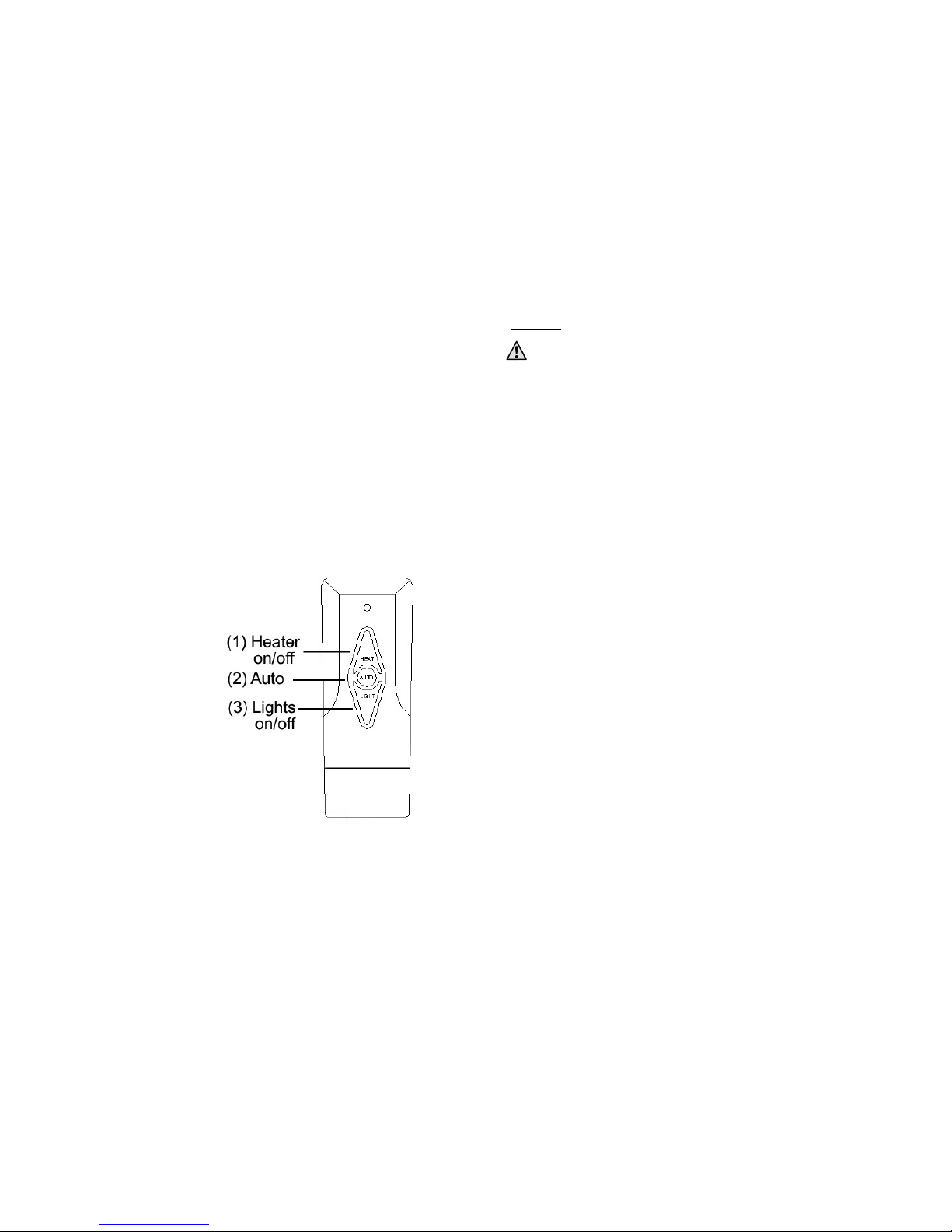
Remote Control
The remote control provides the ability to override the light and
heater functions.
• To manually control the
heater, press the Heater
On/Off button to switch
the heater to be on or
off all the time.
• To manually control the
lights, press the Lights
On/Off button to switch
the lights to be on or off
all the time.
• To return to fully
automatic mode press
the Auto button. If you
are close enough you
will hear the control box
give 1 beep, “Di”. Note:
this will set both the
heater and the lights to
automatic.
• If the mains power
supply is interrupted, the unit will return to the automatic mode
when the power is reapplied.
7
Wiring
Warning: This appliance must be earthed
• All heaters are supplied as standard with 4 metres of cable and a
moulded plug
• We recommend that a RCD be used between the mains plug and
the wall socket.
• If the heater is being used outdoors it is recommended that a
waterproof socket is used for the connection. Otherwise the plug
should be connected to a socket indoors
• If it is required that the heater be permanently installed, then
this should only be carried out by a suitably qualified
electrician in accordance with the current IEEE safety
regulations, and by following the procedure below:
1. This procedure is for the situation where the existing cable
is too short or the heater needs to be permanently wired.
• Ensure that the heater is disconnected from the
mains su ly before roceeding ast this oint.
2. Remove the 4 screws securing the lid to the control box
underneath the heater and remove the lid. Be careful as
the IR on the lid is connected to the circuit board in the
box.
3. Unscrew and remove the supply wires from the terminal
block on the circuit board.
4. Slacken the barrel nut of the compression gland and
withdraw the cable.
5. Remove the barrel nut from the old cable and place onto
the new cable. Ensure that this cable contains Live, Neutral
and Earth wires and its diameter is 8mm; larger cables
may require a replacement cable gland. The cable must
have a minimum cross sectional area of 1.00mm².
6. Feed the cable through the compression gland and connect
the Live, Neutral and Earth wires to the appropriate
terminal block.
7. Fit and tighten up the barrel nut, ensuring that there is
some slack cable inside the box.
8. Carefully replace the lid and tighten the screws until no gap
can be seen between the lid and the box to ensure that the
box remains resistant to water ingress.

8
Adjustment
During normal operating conditions the outside of the heater,
especially the glass, reaches a high temperature. Any
adjustments should only be made with the power disconnected
and the heater allowed to cool down if it has previously been
in use
The heater can be operated in any position from horizontal to vertical
providing that the heater tube remains horizontal, AND the black
plastic box housing the electronics is NEVER OSITIONED ABOVE
THE HEATER.
To adjust: Slacken the Side Screws on the bracket and twist to the
desired angle, and retighten the Side Screws. If it is required that the
heater is set to a fixed angle of 30°, 45° or 60° then fit and tighten
the Index Screws before tightening the Side Screws.
Aiming the IR
The IR can be mechanically adjusted both horizontally and vertically
to give you the ability to point it where you like.
If the vertical movement becomes slack it can be tightened using the
finger nut on the side of the elbow,
9
Operation
There are no user adjustments inside the heater.
Please ensure that you have read and adhere to the
Wiring section on age 6
• Switch on the power.
• The control box will sound 4 beeps, “Di, Di, Di, Di”. This
indicates that that the heater is working normally. You may have
to be close to the heater to hear this.
• When the power is first applied the heater will turn on for about
4½ minutes, this is normal. At the end of this period the heater
will enter the Automatic mode.
• The lights will only operate if the natural light levels are low.
• If the ambient tem erature is above 20°C
a) The heater will not operate.
• If the ambient tem erature is between 15 - 20°C
a) The heater will only operate if a person moves within the
reception range of the IR detector mounted below the
heater.
b) The heater will switch on at full power for about 2¼
minutes and then the heat output will be reduced to the
lower power level for a further 2¼ minutes.
c) If the IR detects movement within the first 2¼ minutes at
full power the movement will be ignored. If the IR detects
movement within the 4½ minutes at reduced power the
heater will re-trigger and remain on for a further 4½
minutes at reduced power from the last movement.
d) If the heater is re-triggered after it has switched off then it
will switch back on for 2¼ minutes at full power and repeat
the cycle as in b) & c) above.
Popular Heater manuals by other brands

Taurus
Taurus TROPICANO BAGNO manual

L.B. White
L.B. White Premier TS080 Owner's manual and instructions

Prem-I-Air
Prem-I-Air EH1710 manual

Hatco
Hatco GR Series Installation and operating manual

Indeeco
Indeeco UCI Series Installation, operation and maintenance instructions

Sentiotec
Sentiotec DIR-350-R Instructions for installation and use


Berner
Berner DTU03-DTU03-1026 instruction manual

Koolatron
Koolatron 40105 instructions

Orbegozo
Orbegozo CV 4000 A instruction manual

SPC
SPC Belgravia Classic Installation, operation & maintenance manual

Dantherm
Dantherm Master BC 121 User and Maintenance Book

Parkside
Parkside 393729-2104 Operation and safety notes