SPC Belgravia Classic Instruction manual
Belgravia Classic
Installation, Operation & Maintenance Manual
IOM 69 Issue 4

2IOM 69 Issue 4 – Belgravia Classic Fan Convectors
Contents Page
1|General 3
1.1 |Description 3
1.2 |Receipt and Preparation 3
2|Installation 4
2.1 |Removal of Access Panel 4
2.2 |Transit Protection 4
2.3 |Removing Motor Plate 5
2.4 |Change of Handing 6
2.5 |Mounting 6
2.5.1 |Wall Mounting 6
2.5.2 |Ceiling Mounting 7
2.5.3 |Tall Units 8
2.6 |Wiring 9
2.7 |Electric Motor Protection 9
2.8 |Pipe connections 9
3|Electrical Data 10
3.1 |Control Wiring 10
3.2 |Motor Wiring 10
3.3 |Common Control Options 11
3.4 |Thermostatic Operation 11
3.5 |Switch Operation 11
4|Maintenance 12
4.1 |General 12
4.2 |Filter 12
4.3 |Coil 12
4.4 |Fan Set 12
4.5 |Fusing 12
4.6 |Spares 12
5|Fault Finding 13
5.1 |No Fan Operation 13
5.2 |No Heating 13
6|Waste Electrical and Electronic Equipment (WEEE) Directive 13
6.1 |WEEE Marking 13
6.2 |Information for Customers 13

3IOM 69 Issue 4 – Belgravia Classic Fan Convectors
1. General
1.1 Description
This manual covers the ‘Classic’ and ‘Natural’
models of the Belgravia Fan Convector range.
‘Classic’ units are the cabinet type intended for
either vertical or horizontal mounting. ‘Natural’
models are free convection units for vertical
mounting. Controls can be contained within the
casing to give a clean outline.
The units can be supplied with internal grilles
for visible surface mounting types or with
plenum and/or spigot connections for concealed
mounting in ceiling or wall space, when short duct
connections may be required to serve the heated
space via optional loose grille assemblies.
The ‘Natural’ unit possesses no motor plate as it
relies upon buoyancy driven airow through the
casing. The following sections relating to the motor
plate and its associated controls do not apply to
this type of unit.
1.2 Receipt and Preparation
The units are wrapped and display the SPC
works order number, model reference, site
reference (where appropriate), handing and site
details. Installation, operation and maintenance
instructions, together with wiring and any special
instructions are supplied with the unit.
On receipt, check that all details are correct to the
Customer Schedules prior to opening packaging.
Damage should be reported to the Carrier and to
SPC Oce immediately.
It is recommended that packaging is kept in
place and the units stored in a safe area until the
necessary services are completed, in order to
avoid the possibility of damage on site.
This document and wiring diagram supplied
should be kept with the unit until electrical
installation is complete.
4IOM 69 Issue 4 – Belgravia Classic Fan Convectors
2. Installation
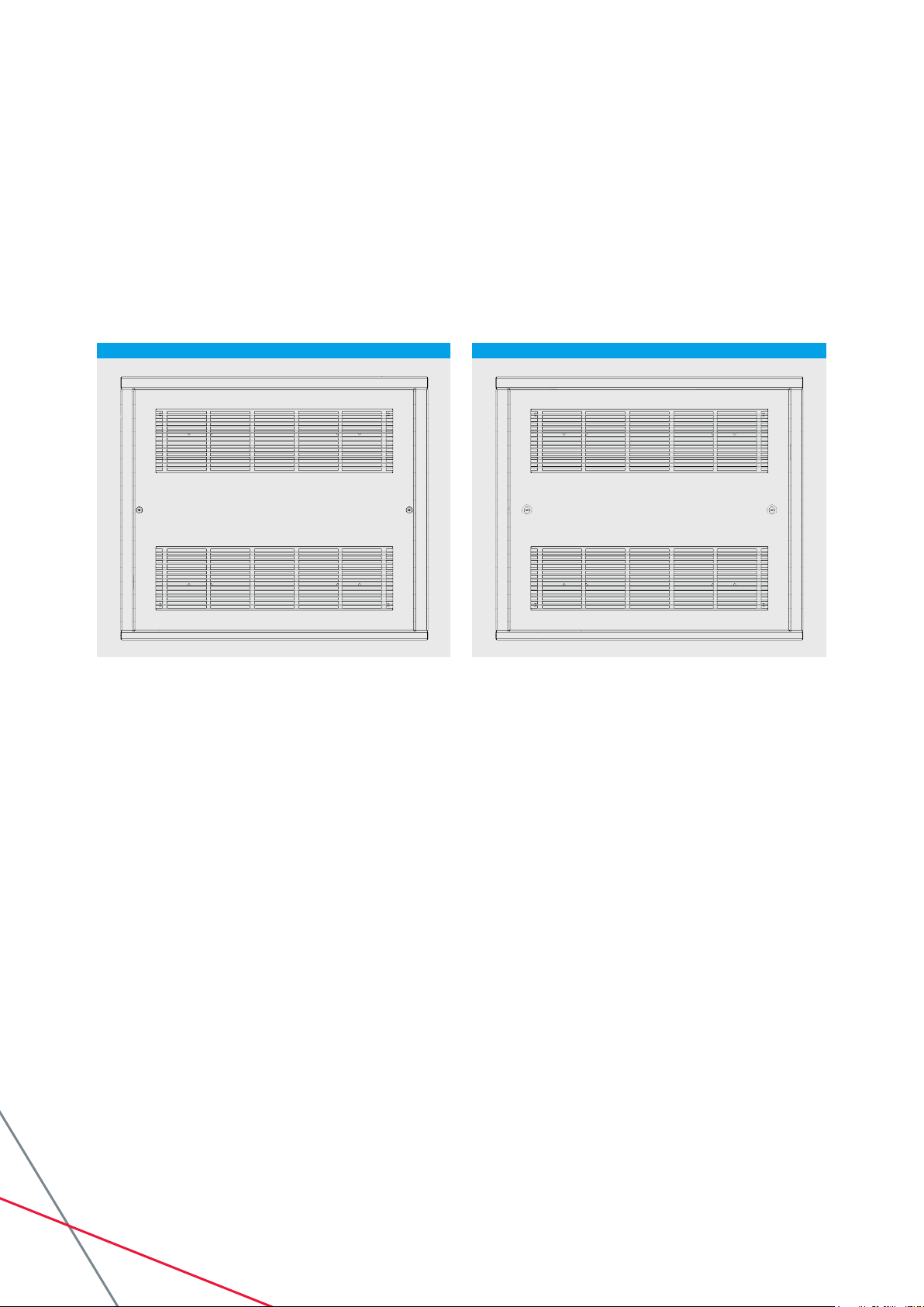
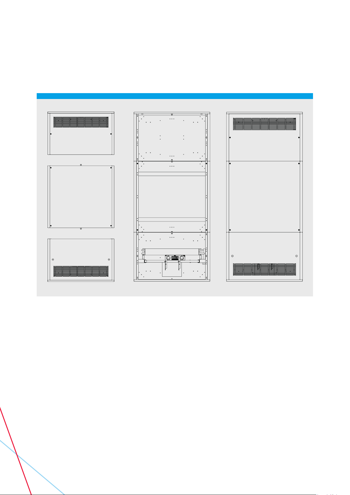
2.1 Removal of Access Panel
1. Tamperproof xings (TAP) are the default method of xing the access panel to the unit. This type of
xing requires unscrewing using an Allen key (provided). If security xings are used then the screw
head will include a pin and a special security Allen key is required for removal.
2. Lock xings may be provided (LAP) and are released using the quarter turn keys supplied.
2.2 Transit Protection
If despatched with a Polystyrene block tted
between side wall & void bracket, this should be
removed before installation.
THIS DRAWING IS THE PROPERTY OF SPC AND IS PROVIDED FOR
INFORMATION ONLY. IT IS NOT TO BE DISCLOSED TO ANY THIRD PARTY
WITHOUT THE WRITTEN PERMISSION OF SPC.
MATERIAL
FINISH
SCALE
TOLERANCE
TITLE
DRAWING No
ISSUE
ISS
ECN
CHANGE
DATE
DRN
CHKD
A3
01
--
ORIGINAL
19/05/2017
PSW
01
SKXXXXXXXX
XXXXXXXXXXXXXXXXXXXXXXXXXXX
XXXXX
NTS
SHEET 1
OF 1
DO NOT SCALE
ALL DIMENSIONS IN
MILLIMETRES UNLESS
OTHERWISE STATED
Main Tel:
+44 (0) 116 2490044
Main Fax:
+44 (0) 116 2490033
Website:
www.spc-hvac.co.uk
Address:
SPC House, Evington
Valley Road Leicester,
LE5 5LU, UK
EXT SALES
INT SALES
SUPPLIER
ACCOUNTS
PRODUCTION
STORES
ISSUED
TO
THIS DRAWING IS THE PROPERTY OF SPC AND IS PROVIDED FOR
INFORMATION ONLY. IT IS NOT TO BE DISCLOSED TO ANY THIRD PARTY
WITHOUT THE WRITTEN PERMISSION OF SPC.
MATERIAL
FINISH
SCALE
TOLERANCE
TITLE
DRAWING No
ISSUE
ISS
ECN
CHANGE
DATE
DRN
CHKD
A3
01
--
ORIGINAL
19/05/2017
PSW
01
SKXXXXXXXX
XXXXXXXXXXXXXXXXXXXXXXXXXXX
XXXXX
NTS
SHEET 1
OF 1
DO NOT SCALE
ALL DIMENSIONS IN
MILLIMETRES UNLESS
OTHERWISE STATED
Main Tel:
+44 (0) 116 2490044
Main Fax:
+44 (0) 116 2490033
Website:
www.spc-hvac.co.uk
Address:
SPC House, Evington
Valley Road Leicester,
LE5 5LU, UK
EXT SALES
INT SALES
SUPPLIER ACCOUNTS
PRODUCTION
STORES
ISSUED
TO
Position of TAP xings Position of LAP xings
5IOM 69 Issue 4 – Belgravia Classic Fan Convectors
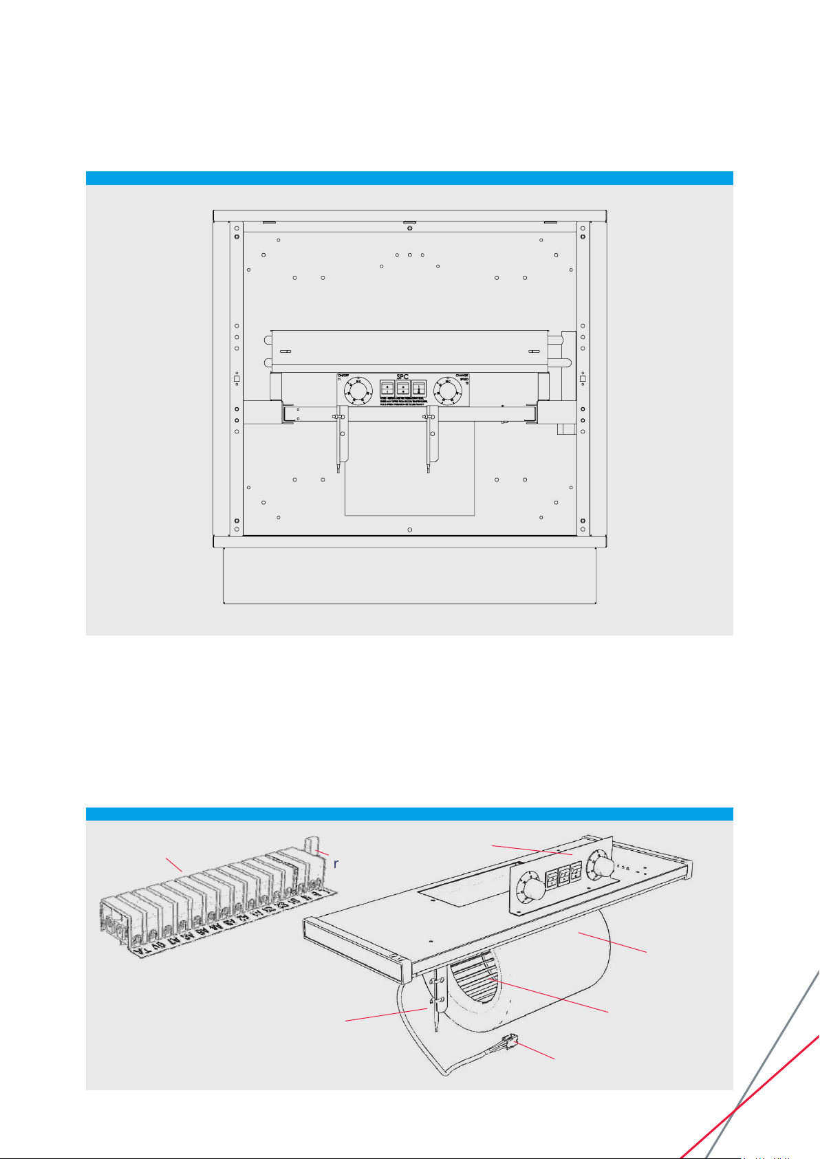
2.3 Removing Motor Plate
IMPORTANT: isolate unit electrically at mains controls.
• Remove front access panel.
• Disconnect plug/socket connections from motor
plate.
• Slide out motor plate, taking care not to damage
fan impellers in any way during this procedure, or
in the replacement.
• On ceiling mounted applications, the motor plate
is retained by bolts through the motor plate &
mounting bracket.
• Ensure motor plate is adequately supported
before releasing the bolts.
Optional
controls
Lift to
remove fuse
EC Motor
Fan Impeller
Split connector for
mainsying lead
Thermostat phial
SPC unit
wiring
PAGE 5 - IMAGE 1
6IOM 69 Issue 4 – Belgravia Classic Fan Convectors
2.4 Change of Handing
Units will have been supplied with pipework
connections on RHS unless specied otherwise. It
is possible to change the handing of the coil heat
exchanger on site by simply reversing its position
inside the unit.
After removing the front panel the coil is easily
removed by releasing two screws holding it in
position on its two support brackets.
The ow and return pipes pass through holes in
the fan plate brackets and if reversing the coil then
the knock-outs in the non-connection side will
need to be removed. The holes now in the side
from which the connections have moved should
be taped over.
After reversing the coil the screws should be
reattached to the brackets to hold it securely in
place.
2.5 Mounting
2.5.1 Wall Mounting
Vertical units can be low level oor mounted or
high level wall mounted.
Low level units are often supplied with a plinth to
hide pipework and lift the unit from the oor. If
they are supplied with a loose plinth then the fan
convector base screws into the plinth via 6-o M5
threaded inserts.
A series of reinforced 6mm dia holes are tted in
the backplate of the unit as shown in the diagrams
below. The wall should be marked out and drilled
with suitable anchors prior to securing through the
backplate.
THIS DRAWING IS THE PROPERTY OF SPC AND IS PROVIDED FOR
INFORMATION ONLY. IT IS NOT TO BE DISCLOSED TO ANY THIRD PARTY
WITHOUT THE WRITTEN PERMISSION OF SPC.
MATERIAL
FINISH
SCALE
TOLERANCE
TITLE
DRAWING No
ISSUE
ISS
ECN
CHANGE
DATE
DRN
CHKD
A3
01
--
ORIGINAL
19/05/2017
PSW
01
SKXXXXXXXX
XXXXXXXXXXXXXXXXXXXXXXXXXXX
XXXXX
NTS
SHEET 1
OF 1
DO NOT SCALE
ALL DIMENSIONS IN
MILLIMETRES UNLESS
OTHERWISE STATED
Main Tel:
+44 (0) 116 2490044
Main Fax:
+44 (0) 116 2490033
Website:
www.spc-hvac.co.uk
Address:
SPC House, Evington
Valley Road Leicester,
LE5 5LU, UK
EXT SALES
INT SALES
SUPPLIER ACCOUNTS
PRODUCTION
STORES
ISSUED
TO

7IOM 69 Issue 4 – Belgravia Classic Fan Convectors
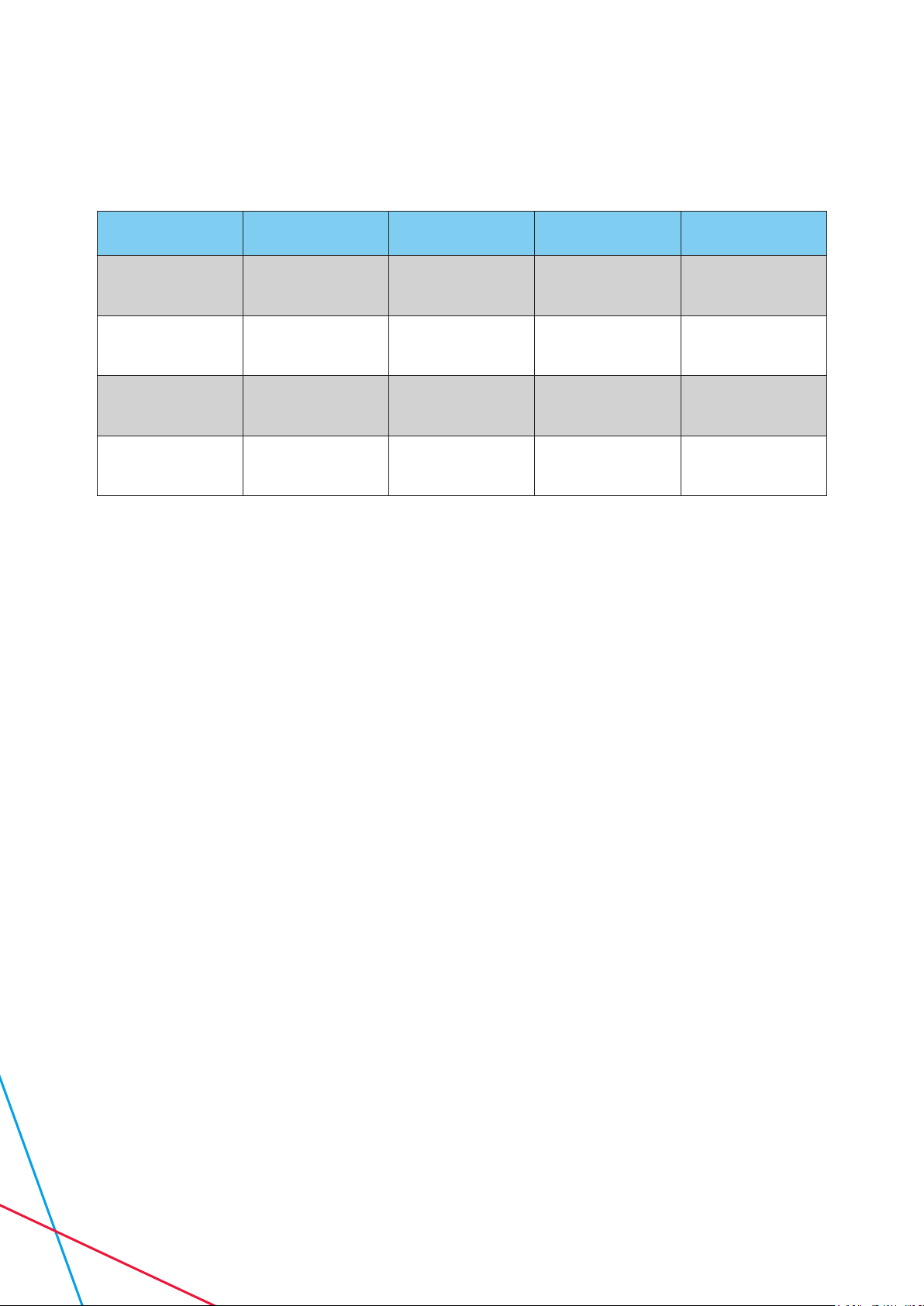
2.5.2 Ceiling mounting
Horizontal units may be bolted directly to the
ceiling/sot via the reinforced 6mm dia holes in
the top plate of the unit. These hole positions are
shown on the sketches below.
Unit Size DIM ‘A’
40 700
60 900
90 1200
150 1500
Unit Size DIM ‘A’
40 700
60 900
90 1200
150 1500
Unit Size DIM ‘A’
40 700
60 900
90 1200
150 1500
Standard unit mounting positions
Double sloping unit mounting positions
Single sloping unit mounting positions
DIM 'A'
600
90
80
6mm HOLES x 6
C
L
C
L
DIM 'A
725
90
80 440
6mm HOLES x 6
C
L
850
DIM 'A'
205
90
6mm HOLES x 6
C
L
C
L
PAGE 7
KEEP THE TABLES
DIM 'A'
600
90
80
6mm HOLES x 6
C
L
C
L
DIM 'A
725
90
80 440
6mm HOLES x 6
C
L
850
DIM 'A'
205
90
6mm HOLES x 6
C
L
C
L
PAGE 7
KEEP THE TABLES
DIM 'A'
600
90
80
6mm HOLES x 6
C
L
C
L
DIM 'A
725
90
80 440
6mm HOLES x 6
C
L
850
DIM 'A'
205
90
6mm HOLES x 6
C
L
C
L
PAGE 7
KEEP THE TABLES
8IOM 69 Issue 4 – Belgravia Classic Fan Convectors
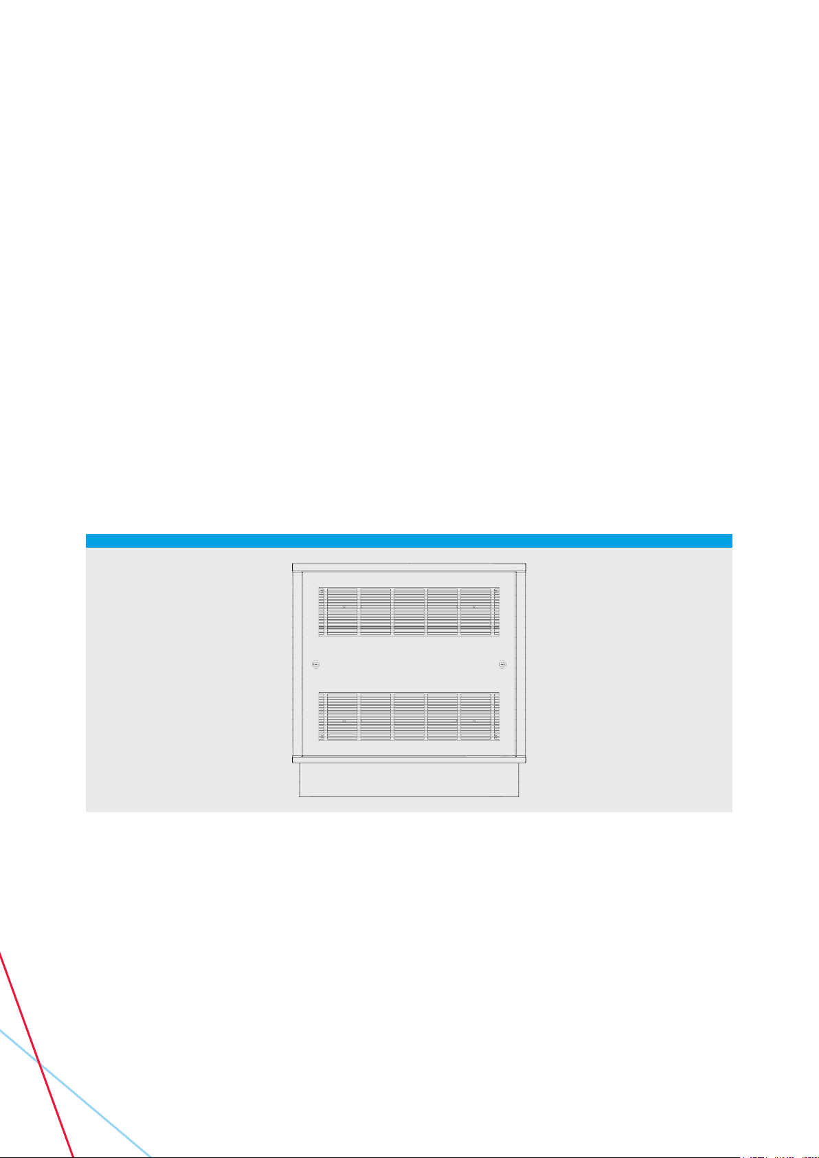
2.5.3 Tall units
Tallboy type units for vertical mounting are
supplied in three sections to assist with transport
and movement on site. All three sections should
be screwed together using the screws/nuts/
washers supplied. The assembly should be
undertaken either in the nished position or as
close to it as is practical.
PAGE 8

9IOM 69 Issue 4 – Belgravia Classic Fan Convectors
2.6 Wiring
All electrical work should be carried out in
accordance with current I.E.E. regulations.
See the wiring diagram supplied with the unit for
connection details.
All motors are tted with internal self-resetting
thermal overload protection (see note below) and
are equipped with a motor plate mounted
Anti-surge fuse (see spares list). All units are
supplied with a 2 metre length of 3 core cable as a
ying lead. This is normally coiled within the unit.
The customer should drill and gland to suit the
installation. The supply should be wired through
a suitable means of isolation such as a fused spur
box or similar. Recommended fuse is not more
than 3A (for standalone unit).
2.7 Electric Motor Protection
On ceiling mounted and reverse airow
applications where the fan motor is switched o
for long periods, with hot water still circulating
through the heat exchanger in excess of 82ºC
(180ºF), it is recommended that a system be
employed which automatically closes the hot water
supply valve to prevent damage to the electric
motor due to overheating.
2.8 Pipe connections
Standard units are supplied with ow and return
pipe connections sized at ¾” BSPP female. For
the standard 2 row coil heat exchanger the ow
and return pipes are interchangeable. If the fan
convector is equipped with a 3 row coil which
has ½” BSPP female connections then this will be
an enhanced output coil for use against low hot
water temperatures or owrates. For this type of
coil the connection coming from the leaving air
face should be made the ow and the connection
closest to the fan outlet, on the entering air face,
should be made the return connection. This
ensures that the optimum heat transfer capacity
can be achieved from the coil.
If a modulating valve is tted as a part of an LST
unit then the nal pipe connections will be in
15mm copper and the ow and return pipes
should comply with any arrows stamped on the
valve body.
10 IOM 69 Issue 4 – Belgravia Classic Fan Convectors
3. Electrical Data
Unit Speed Airow (L/S) EC Power Draw
(W) EC SFP (W/L/S)
Bel 40
L
N
H
89
112
140
11
16
27
0.12
0.14
0.19
Bel 60
L
N
H
108
184
223
15
53
84
0.14
0.29
0.38
Bel 90
L
N
H
120
231
317
18
34
73
0.15
0.15
0.23
Bel 150
L
N
H
180
289
329
22
58
80
0.12
0.20
0.24
3.1 Control Wiring
The wiring for internal control options is sited on
the motor plate. Wiring from the motor plate to
casing control options is via split connector break
plugs. Customer wiring should be made to the
Customer Connection Box for other than the
ying lead. Wiring to other than this point may
result in voiding of the warranty.
A wiring diagram showing customer connections
is included with each unit.
For wiring other than that specied on the
Customer’s order, the SPC Technical Department
should be contacted.
3.2 Motor Wiring
The motors are Electronically Controlled. They
have a 230v AC supply but are controlled via a
10v DC signal. A circuit board on the motor plate
has three potentiometers tted which give the
low/normal/high speed.
If only one speeds is specied this will be normal
unless otherwise stated.

11IOM 69 Issue 4 – Belgravia Classic Fan Convectors
3.3 Common Control Options
Reference** Function
Thermostat T-1 On - o
T-2 Change speed
LTC Low water temperature fan cutout
ALTC Adjustable low water temperature fan cutout (remote)
Switches RS-1 On - o
RS-2 Summer - winter
RS-3 Change speed (3 speeds)
**Additional References: Motor plate mounted = B, Case mounted = C, Remote = R
3.4 Thermostatic Operation
The T1 and T2 Thermostats both have graduated
scales to cover their range of operation. Since
the thermostatic bulb is frequently unit mounted
it may be oset by various amounts from the
measured room temperature.
Set the knob at mid-range and adjust to suit
comfort conditions within the room.
The range corresponds to a sensed temperature
range of 10°C to 30°C.
T1 and T2 are adjustable and determine the
comfort room temperature range. Set T2 for the
low and T1 for the high point. Example: T2 16°C
and T1 20°C.
The LTC is not adjustable (45°C) and provides
a fan cut-o for the situation when the water
temperature is not suciently high to provide
warm blown air from the fan convector. The LTC
is mounted at the non-void end of the unit, and
is screwed to a copper disc which is brazed onto
a return bend of the coil.
3.5 Switch Operation
The RS1 switches do not in themselves isolate
the unit.
The RS2 Summer-Winter switch provides an
override for the LTC and T1 (where tted),
enabling the fan to operate in the summer, for air
re-circulation.
The RS3 Change Speed Switch delivers one of
three voltage tappings to the motor. Where used
in a remote application care should be taken
when wiring into the customer connection box to
ensure correct sequencing

12 IOM 69 Issue 4 – Belgravia Classic Fan Convectors
4. Maintenance
4.1 General
WARNING! Electrically isolate the unit prior to work commencing
4.2 Filter
The AF3 air lter is motor plate mounted as
standard. The lter is held in place between 2
brackets and is removed by sliding it out. The
AF1 lter, where specied, is tted underneath
the heat exchanger and can be slid in and out
of two short side rails. The AF2 inlet air lter can
be specied as either internal or external and is
tted on the air inlet grille.
Filters should be gently tapped to remove most
of the accumulated dust and either vacuumed
clean or washed in lukewarm water with
detergent. Rinse in clean water and allow to dry
naturally before replacement.
If an inlet plenum is tted, the lter is removed
by dismounting the access panel to gain access.
4.3 Coil
Remove access panel and clean the coil with
a brush or by vacuuming, taking care not to
damage the coil surfaces.
4.4 Fan Set
The motor has sealed for life sleeve bearings,
which under normal circumstances require no
user maintenance. The motor deck is accessed
by means of the access panel and is readily
removed if required. Occasional vacuuming or
cleaning of the motor plate is recommended.
4.5 Fusing
Fan motor- Anti-surge 20mm x 5mm 2A to
BS4265/IEC127
(see wiring diagram).
4.6 Spares
• Fuses - as above
• Filters - quote model number (BEL 40/60 etc.)
or unit width. Units manufactured pre 1995 will
require dierent lters to later units
• Controls - as specication
• Motor - quote model number on motor plate
Quote motor plate mounted (AF3) or
coil mounted (AF1) or grille mounted
(AF2).
Quote wiring diagram number or
marked number if possible.
13IOM 69 Issue 4 – Belgravia Classic Fan Convectors
5. Fault Finding
5.1 No Fan Operation
Check fuse on motor plate.
Check power supply to unit.
Check loose wiring and breaker plugs or
damage to wiring.
Check switches
Check impellers run freely.
5.2 No Heating
Check thermostat operation (change set point
to maximum) where tted.
Check integrity of wiring.
Check coil vented.
Check hot water to unit.
Check thermostat bulb in airstream.
Check LTC contact on pipe-work or return bend.
6. WEEE Directive
(Waste Electrical and Electronic Equipment)
6.1 WEEE Marking
All products that are subject to the WEEE
Directive supplied by SPC from 2007 are
compliant with the WEEE marking requirements.
Such products are marked with the “crossed out
wheelie bin” WEEE symbol shown here.
SPC WEEE Certicate No: WEE/KF0742YR
6.2 Information for Customers
According to the timelines and requirements of
European Union member state WEEE legislation,
the following customer information is provided
for all SPC supplied products subject to the
WEEE directive.
This symbol on the product or on its packaging
indicates that the product must not be disposed
of with normal household waste.
Instead, it is your responsibility to dispose of
your waste equipment by arranging to return
it to a designated collection point for the
recycling of waste electrical and electronic
equipment. By separating and recycling your
waste equipment at the time of disposal you will
help to conserve natural resources and ensure
that the equipment is recycled in a manner that
protects human health and the environment. For
more information about how to recycle your SPC
supplied waste equipment for recycling, please
contact our customer services department
on +44 (0)1162490044 or
customerservice@spc-hvac.co.uk.

SPC House
Evington Valley Road
Leicester
LE5 5LU
T: 0116 249 0044
E: spc@spc-hvac.co.uk
spc-hvac.co.uk
IOM 69 Issue 4 – Belgravia Classic Fan Convectors
Table of contents
Popular Heater manuals by other brands


Comfort Glow
Comfort Glow CEH625 owner's manual

Gabarron
Gabarron Elnur ECOMBI HHR Series installation instructions

KING
KING PCKF Series Important instructions

Twin-Star International
Twin-Star International Duraflame 9HM9273 manual

THERMOCOAX
THERMOCOAX isopad IGB-G Series operating instructions

MILL
MILL CO1200WIFI3 Assembly and instruction manual