Smooth-Air HEX390 Series Installation and operation manual

HEX390 Installation & Commissioning Instructions September 2016 1
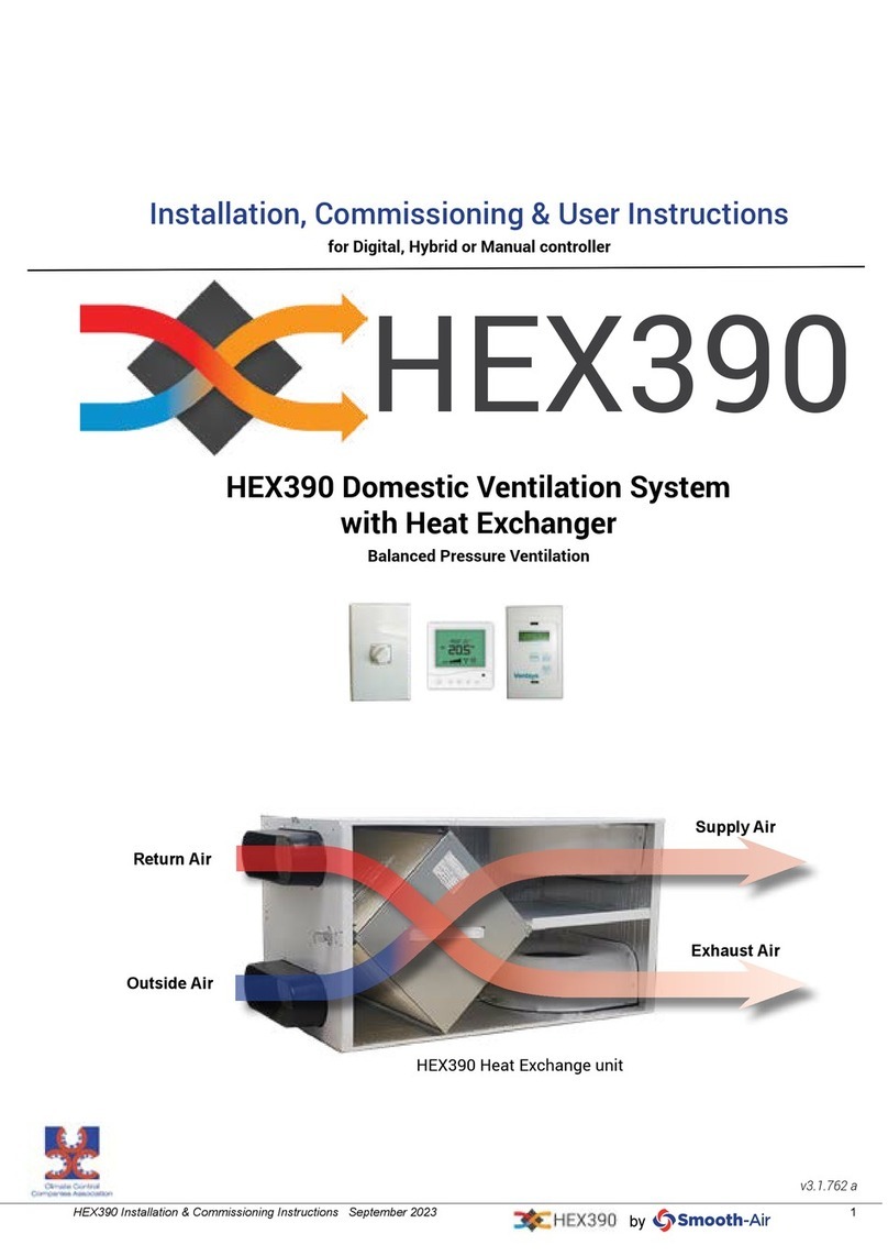
HEX390 Domestic Ventilation System
with Heat Exchanger
Balanced Pressure Ventilation
Installation & Commissioning Instructions
for Digital or Manual controller
HEX390
Supply Air
Return Air
Exhaust Air
Outside Air
HEX390 Heat Exchange unit
v3.1.762

HEX390 Installation & Commissioning Instructions September 20162
WARRANTY RETURN
Upon installation, please send to the manufacturer, c/o PO Box 8358, Christchurch
(on request by the dealer).
Purchaser: _______________________________________________________________
Address: _______________________________________________________________
Description: HEX390 _______________________________________________________________
Serial number: _______________________________________________________________
Purchased from / Dealer: _______________________________________________________________
Dealer invoice number: _______________________________________________________________
Date of installation: _______________________________________________________________
Installed by: _______________________________________________________________
HEX390 Warranty
5 years manufacturing warranty from date of rst retail purchase.
This HEX product, when delivered to you in new condition from a HEX authorized dealer and used in normal
conditions, will be free from any defects in manufacturing, materials and workmanship for the periods set out
above (“Warranty Period”):
Any faulty goods will be repaired or replaced via the HEX dealer.
This warranty is for the manufactured product, it does not include installation or removal.
Contents
HEX390 Warranty 2
Pre-checks & Recommendations 3
Technical Data 4
Kit Contents 5
Installation Instructions 6-9
Hex Digital Wiring Schematic 9
Wiring schematic - Manual 3speed switch 10
Wiring schematic - Digital controller 11
Installer’s recommended settings: 12
Trouble Shooting 12
Digital Controller - Commissioning Instructions 13
Digital Controller - Commissioning Instructions - Menu Options 14-15
User Operating Instructions 16

HEX390 Installation & Commissioning Instructions September 2016 3
Please Note: These installation and commission instructions are merely a set of guidelines for effective
installation and setup of the system to yield maximum performance. Actual installation may vary due to
the vast variety of the house architecture and climates. Ensure you fully understand this manual and plan
ahead before commencing the work. Unit must be installed by a suitably qualied person and all electrical
terminations must be carried out by a registered electrician to New Zealand standards.
using maximum of 5 supply outlets for house
oor area not more than 280m2
10. The G3 pre-lter must be cleaned or replaced
every 9 months or when necessary.
11. Isolate electrical supply before commencing
any electrical work.
12. For return ducts located in open plan living
rooms with inadequate kitchen extraction, or
with smokey log burners, we recommend a
pre-lter (see over page)
13. In colder areas an auxiliary inline duct heater
is recommended (see over page)
Pre-checks & Recommendations
1. Before installation, ensure the system suits
your requirements
2. Check that adequate heat sources are present
for the optimum performance of the system.
3. Make sure that enough space is available for
the installation of the system.
4. Plan and mark out the location of the unit and
grilles before commencing
5. Before cutting holes for diffusers, check that
the penetration is clear of ceiling joists, roof
structure and electrical cabling or plumbing.
6. For optimum performance, please ensure the
house is well insulated and does not have open
penetrations into the ceiling.
7. Keep all the duct runs to minimum and avoid
tight bends.
8. Acoustic ducting (Silentex) should only be
used on the supply and exhaust sides (not the
return and intake lines).
9. For optimum performance, please consider
supply
controller
Extract
Fresh Air
Exhaust Air
HEX390

HEX390 Installation & Commissioning Instructions September 20164
HEX390 unit
Air Flow (max) 390 m3/ hr (110 l/s)
Sensible Effectiveness (max) (approx) 80%
Dimensions (mm) 400 x 400 x 850
Weight 20.75 Kg
Filter (replaceable) EU3
Duct connection equivalent diameter 200 mm
Electrical
Rated Voltage 220-240 VAC
Rated Wattage 240W
Fan Fuse 2A Ceramic Slow Blow
Controller Fuse 1A Ceramic Slow Blow
Heater Fuse 10A Ceramic Slow Blow
Diffusers & cut out size
Cut out size
Lounge supply (200mm Swirl Diffuser) 222mm
Bedrooms supply (150mm Cone Diffuser) 180mm
Return (200mm Circular Egg-Crate) 262mm
Fresh air / Exhaust (200mm Square
Louvre)
Optional Extras
Item Code
F7 Filter FBPF7
Filter Box for F7 lter FBP200
Additional 150mm supply HEXext150supply
Additional 200mm supply HEXext200supply
Additional Extract HEXext200extract
750W heater (up to 180sqm) HT
1500W heater (up to 280sqm) HT15D
Technical Data
200mm circular eggcrate
- return
150mm cone diffuser
- bedroom supply
200mm Swirl Diffuser
- lounge supply

HEX390 Installation & Commissioning Instructions September 2016 5
Hex390digi
Hex390man
HEX4roomkit
HEX3roomkit
HEXext150supply
HEXext200supply
HEXext200extract
HEX Exchanger Body 1 1
16mmx 5m drain tube and tting 1 1
Digital controller Kit 1
Manual controller kit 1
Hanging wire and ttings 2 2
Supply
200mm swirl diffuser + Adaptor 1 1 1
150mm circular cone diffuser 3 2 1
200mm x 6m Silentex 1 1
200mm x 3m Silentex 2 2 1
150mm x 3m Silentex 321
200/200/200 ’Y’ connection 1 1 1
200/150/150 ‘y’ connection 1
150/150/150 ‘Y’ connection 1
200/150/150/150 Branch 1
Extract
200mm Egg crate circular grille 2 1 1
200mm x 6m insulated duct 1
200mm x 3m insulated duct 3 1
200/200/200 ’Y’ joint 1 1
Fresh
200mm square Louvre Grille 1 1
200mm x 6m nude duct 1 1
Exhaust
200mm square Louvre Grille 1 1
200mm x 6m Silentex 1 1
Components
6m Tape 1 1 1
50m Tape 1 1
Kit Contents

HEX390 Installation & Commissioning Instructions September 20166
Hex Unit
It’s best to install over the bathroom, garage or
similar location where occupancy is minimal and
also where the unit could be easily accessible for
servicing. Securely install the unit horizontally by
using the provided installation kit as illustrated
below. Ensure enough space is provided for the
installation of the condensation drain adaptor and
tubing (located inside the unit). Once duct and
ttings connected, unit needs to be level for drain
to work properly.
200mm x 3m
insulated
200mm Circular Eggcrate
200mm x 3m
insulated
200mm x 3m
silent
Supply
Exhaust
Extract
Fresh
200mm x 6m
silent
150mm x 3m
silent
150mm x 3m
silent
150mm x 3m
silent
200mm x 3m
silent
200mm x 3m
insulated
Drain
200mm x 6m
nude
6m
200mm x 6m
silent
200mm louvre sq grille
200mm louvre sq grille
150mm Cone Diffuser
200mm Swirl Diffuser
150mm Cone Diffuser
150mm Cone Diffuser
200mm Circular Eggcrate
General Layout
• Upto6timesfastertoinstallthantraditionalmethods
• Keyless-notoolrequiredforadjustment
• Ergonomicbuttonsallowrapidadjustment
• Discreetandaestheticdesign
• Loadratedat45kgwitha5:1safetyfactor
• Suppliedasaready-to-usekit
The Gripple Express is a fast locking solution for quick and easy suspension of signage,
shopfitting display, HVAC, plumbing, cable containment and lighting.
ADVANTAGES
PRODUCT DIMENSIONS END FIXING
INSTALLATION RELEASE
Gripple Express No.2
Gripple Ltd|TheOldWestGunWorks|SavileStreetEast|ShefeldS47UQ
www.gripple.com
PI-47-ENG
D W
L
Wire rope diameter L (mm) W (mm) D (mm)
2mm 28.4 21.4 11.6
* This product is silicone free
Each ready-to-use kit comes with an end fixing of
your choice. All types can be ordered to the length
you require (up to 10 metres or more).
For further detailed information on any of our end
fixings, please visit our website or contact us using
the information below.
1
2
G-XP2-go Express Gripple operation
Installation Instructions
Use supplied Gripple kit to
hang unit level

HEX390 Installation & Commissioning Instructions September 2016 7
HEX
Drain
adaptor
P trap in condensate
drain hose
Drain Adaptor
Bottom of unit
Drain installation
Securely attach the provided drain adaptor
(located inside HEX lter cover) to the bottom of
HEX unit. HEX unit must be level. Run the drain
tubing from the adaptor to outside with a “P trap”,
as illustrated.
Fresh Air and Exhaust Grille
Install underneath the sot with a minimum 6m
separation between the exhaust and fresh air
grille to prevent cross contamination. Use the
nude and acoustic ducting (Silentex) from the
fresh air and exhaust grilles respectively to the
unit. If access is limited, please consider using
through roof cowls, such as the MAD204T.
Return Grilles
Mount the provided return air grilles as suits the
homeowner, one in the heat source room and one
in the hallway central to the supply grilles. Use
the Insulated ducting from the grille to the unit.
Exhaust Air
Return Air lter
HEX body
Supply Air
Return Air
Outside Air
Fresh Air lter
Filters
The unit is supplied with two G3 pre lters. If
required, an F7 lter (FBP200+FBPF7) can be
installed in the supply side for extra ltration.
Alternatively a standard EU2 lter can be used
(FBP200+FBPF2).
Supply Grilles
Mount the provided supply air grilles as suits the
homeowner, bedrooms and living areas, with a
maximum of ve outlets for optimum performance.
Use the acoustic ducting. It is recommended that
the supply outlet be between these grilles and the
unit.
Cleaning the lters
The internal lters are designed as secondary
lters (there should be extended surface lters
cleaning the air before reaching the unit).
However, when unit lters are heavily soiled,
wash or replace the lter material with "HexFilter"
(234x380mm) or "HexFilter 222" (222x380mm) for
2015 and earlier models.
To wash: use vacuum cleaner to remove excess
dust, then wash in warm detergent treated water,
keep lters at or leave in frame to wash.

HEX390 Installation & Commissioning Instructions September 20168
HEX Attic box
Terminate
separately
the grey &
brown wires
from the
HEX unit
Attic control box
Attic box can be mounted
on or near the unit.
Wall Controller
Digital or manual 3 speed controller (located
inside the attic box for transportation and
storage), should be installed in the hallway or
lounge, adjacent to one of the extract grilles.
Temperature sensor
mounted in fresh air inlet
Temperature
sensor wire
plugs in here
Cat5 cable to digital
wall controller
For digital controller, mount
with pack glands downwards
In-line Duct Heater (for digital model only)
If installing HT or HT15, ensure the duct heater
is securely installed horizontally and ensure the
air ow meets the minimum required.
Digital sensor (for digital model only)
Placed into incoming fresh air ow, through the
pre-drilled hole, and xed with the cable tie.
Installation Instructions (continued)

HEX390 Installation & Commissioning Instructions September 2016 9
Internal on/off Thermostat - Digital Controller
The thermostat should be disabled for digital
controller, as the digital controller should control all
airows.
Internal on/off Thermostat - Manual Controller
(Optional) The internal thermostat (2core cable
from the HEX unit) can be set so the unit turns off
if the temperature exceeded the set point (eg if
thermostat is set to 30, the unit will turn off if the
incoming fresh air is above 30ºC).
Return Air lter
Fresh Air lter
Optional
Internal On/Off
Thermostat
Electrical
Supply
230VAC
by installer
Electrical supply must be installed
by a registered electrician as per the
schematics on pages 10-11.
Heater Connection
Return Air
(Shielded, don't cut)
Cables
The 5 core cable (fan loom) goes to the
attic box , for both manual and digital
versions.
The 2 core cable (internal thermostat) is
optional for the manual controller - leave
unconnected for digital version.
5 core cable
Fan loom
2 core cable
internal thermostat
(optional for manual
controller only)

HEX390 Installation & Commissioning Instructions September 201610
Wiring schematic - Manual 3speed switch
The attic box also comes
with a two core wire for
use with the optional
thermostat.

HEX390 Installation & Commissioning Instructions September 2016 11
Wiring schematic - Digital controller
PN P1N P3
NNCC
240VAC MOTOR HEAT Vent
Circuit Board
Patch lead socket
Isolator
Switch.
NO
Heat Sensor Plug.
Grey (HT15D Only)
Green
Blue
Brown
Grey
Mode
Dry-Matic
Fan
Diverting
Branch
Motor
Heater
1
2
3
N P
PN
If damper operates in "reverse"
change CW<>CCW switch on
motor body to correct.
For digital controller, mount attic box
with pack glands downwards
Supplied cable for the
duct heater for
HT07 is three core.
HT15 is four core
- wire to earth, P3 & N.
Note wiring connection
details supplied with
heater.
Attic Controller
(for HT15 only)
Heater (for HT07 &HT15)
Optional
Attic damper kit
1
2
3
PN P1N P3
NNCC
240VAC MOTOR HEAT Vent
Circuit Board
Patch lead socket
Isolator
Switch.
NO
Heat Sensor Plug.
Grey (HT15D Only)
Green
Blue
Brown
Grey
Mode
Dry-Matic
Fan
Diverting
Branch
Motor
Heater
1
2
3
N P
PN
If damper operates in "reverse"
change CW<>CCW switch on
motor body to correct.
Diverting
branch motor
Hall controller
For heated units only
Heat
sensor
For attic damper kit, ensure the heat
sensor is in duct, upstream of lter box.
High
Medium Terminate
Terminate
E
Black
Brown
Grey
Blue
Grn/Yel
Basic HEXbody wiring to attic box
Supplied cable for the fan unit is
ve core - wire to N & P1
(HT15 only)
N
E
P1
Low
N
HEX unit
Terminate
seperately
Cable for electrical
supply is three core
and pre-wired to
the attic controller.
NO NC
See p8 for full
image
Terminate grey
& brown wires
from the HEX
unit separately

HEX390 Installation & Commissioning Instructions September 201612
Installer’s recommended settings:
Default Installer
recommended
1. Heater Kit Yes Yes / No
Heater ON time: 19:00 ........ : ........
Heater OFF time: 07:00 ........ : ........
2. Max Fan Speed 60% ....%
3. Fan Speed Heat 45% ....%
4. Winter Mode Yes* Yes / No
If Yes, shut down temp: 0 °C .....°C
5. Filter Timer No Yes/No
If lter timer Yes: 240 days .....days
6. I/Side Ref Temp 18°C....°C
7. O/Side Ref Temp 12°C....°C
8. O/Side Degree Offset 0°C....°C
9. I/Side Degree Offset 0°C....°C
10. Heat P/band 5°C....°C
11. Summer Temp S/down 27°C....°C
12. User Sys Off On / Off
13. Factory Reset
• Optional attic damper kit installed No Yes / No
Installer Details:
NB: The attic damper
kit option is always
available on the main
interface, but it does
not affect operation if a
damper is not installed
Symptoms Solutions
Fans not operational • Check circuit breaker in the mains switch board
• Check power to the hall controller. If hall controller is active, check
the 2A fuse in the attic controller, after isolating the power to the unit.
Fan too noisy • Check the Max Fan Speed setting match the recommended setting
for the house size, lower the speed of fan if necessary
Outside temperature incorrect • Set the correction in commissioning menu
Inside temperature incorrect • Set the correction in commissioning menu
Heater Fault • Check fans are operational
• Check fan speed heat setting, increase the value if necessary
Unexpected Filter Full notication • Check the setting in commissioning menu and adjust if necessary
Trouble Shooting
All electrical work must be conducted by a qualied electrician to NZ standards.
*some models Winter
mode default is 'No'

HEX390 Installation & Commissioning Instructions September 2016 13
The Heat Recovery Digital Controller has a
number of features available to customize
the system to suit house size, layout and user
preferences.
The Setup menu is accessed by pressing the
↑ & ↑ buttons together for about 5
seconds until the display reads ‘Setup Menu’.
The controller comes preset with default factory
settings, these can be reinstated using menu
item ‘Factory Reset’ (number 13 on next pages).
If the unit is not set up correctly to suit the
house, performance may be reduced.
There are a number of options which can be
scrolled through by pressing the Mode button
as below.
If no button is pressed within 15 seconds the
controller automatically reverts to normal
operation. Once a button is pressed a backlight
will operate and remain on for 20 seconds after
the last keystroke.
Press ↑ button to toggle between Yes/No
or other options, then press ‘Mode’ to advance
through the menu. Once a setting is changed on
the menu, it is automatically registered.
Hold down the ‘Mode’ key to accelerate through
the menu,
Options are on following pages.
Please note: if settings are changed from
recommendations, performance of the unit may
be reduced.
Display Key :
Δ- Outside Air Temperature
□- Inside Air Temperature
Winter - winter mode is on
Wint off - winter mode has automatically
shut the system off
H - Heater is tted
Digital Controller - Commissioning Instructions
Fan Speed
Status
Outside Air
TempΔ
Operating
Mode
Inside Air
Temp
Fan Speed
Increase
[Y/Ntoggle]
Time
Fan Speed
Decrease
Mode
[to scroll]
Use up arrow to change
Use Mode button to scroll
through options
Press up and down arrows
together for 5 secs to get to
Setup Menu
The following commissioning menu is for v3.1.762 .
Programme version number is written on the back of each board. The version number will also display when the
device boots for the rst time following any power outage.
Δ
□□

HEX390 Installation & Commissioning Instructions September 201614
1. Heater Kit Yes/No (default Yes)
If No - heater options are removed from all menus.
If Yes - heater options are available in User menu - Heater On/Off for continuous or night
heat (to times as set below) .
To set night heat option:
• press up arrow to select Yes, then:
• press mode to display ‘Heater Times’>display then changes automatically to show
the current settings (default: ) >display changes again to ‘Change Times’
Yes/No (default No).
• At this point, use then to select Yes & change the times.
• Select desired Heater ON time in Hours:Mins using or
• Select desired Heater OFF time in Hours:Mins using or
• Heater Test Yes/No (default No)
• change to Y, heater test will be performed. If there are any faults (including no
heater connected), ‘Heater Fault’ will display. (See menu item 3.Fan Speed Heat for
possible Heater Fault causes.) To reset Heater Fault display, turn unit off.
2. Max Fan Speed (default 60%) – Range is 35% to 100% adjustable in 1% increments using up
& down arrows. For a large house set to a max of 100%.
House size Max Setting
Upto 120m2 50%
120m2 - 180 m2 70%
180 m2-250 m2 100%
280 + Two or more units recommended
3. Fan Speed Heat (default 45%) – Range is 30% to 60% adjustable in 1% increments using up &
down arrows.
Fan Speed Heat sets a minimum speed for the fan to ensure enough airow for the heater
to operate. There are many duct fan combinations, some more restrictive to airow than
others. Therefore, when setting up, the installer must check that the heater operates
without ‘Heater Fault’ ashing on the display. ‘Heater Fault’ is triggered when the heater
is operating but draws no current, this is most often due to insucient airow causing
the airow proving switch to cut off. If there is insucient airow, increase the ‘Fan Speed
Heat’ setting. Heater fault may also be caused by manual reset thermal cutouts which may
need to be reset.
4. Winter Mode Yes/No (default Yes). Winter mode shuts the system down when the outside air
temperature gets below eg 2°C. If Winter Mode is on, another menu item will appear to allow
adjustment of actual shut down temp: Range -2°C to +5°C.
Heater ON 19:00
Heater OFF07:00
Digital Controller - Commissioning Instructions - Menu Options
Digital Controller - Commissioning Instructions (continued)

HEX390 Installation & Commissioning Instructions September 2016 15
5. Filter Timer Yes/No (default No) – Controller counts hours run by the fan and when lter is
due for a change the display ashes with ‘Swap Filter’. If lter timer is set to ‘Yes’, another
menu appears allowing lter period adjustment (240 day) (range 150 - 240 days). The lter
timer can be reset in the user menu at any time. The timer should be reset after the lters
have been cleaned or replaced.
6. I/Side Ref Temp (default 18°C) Range 16-24°C. This is the reference temperature for the
inside of the house, used for:
• Heating – when house temp (IS) is lower than 18°C (default) and outside temp (OS) is
lower than 12°C (default) the heater will operate (if tted).
• Summer – when house temp (IS) is higher than 18°C (default) and outside temp (OS) is
higher than 27°C (default) the unit will shut-down.
7. O/Side Ref Temp (default 12°C) Range 8-16°C. This is the reference temperature for the
outside air, below which heater operates (if tted).
8. O/Side Degree Offset (default 0°C) this allows unit to be calibrated in the unlikely event that
outside air temperature reads too high or low (adjustment range -10°C to + 10°C).
9. I/Side Degree Offset (default 0°C) - As above.
10. Heat P/band (default 5°C) Range 1-7°C. Heat Proportional Band - When heater is tted and
conditions call for its operation, heater will start heating at 20% when OS (outside) drops to
reference temp (default 12°C), and will operate at 100% when temperature has dropped by a
further (default) 5°C (ie when OS is 7°C).
11. Summer Temp S/down (default 27°C) Range 25°-35°C. When OS (outside temp) is greater
than 27°C and IS (inside temp) is greater than 18°C, the system shuts down.
12. User Sys Yes/No (default No) - when set to ‘Yes’, there is an option in the User menu to turn
the system On/Off. Once the system has been turned off, any key may be pressed to return
the unit to regular operation.
13. Factory Reset Yes/No (default No). ‘Yes’ resets all menu items to the factory default settings,
these default settings are shown in brackets above. This option will ask for conrmation to
‘Erase Sengs?’ before performing the factory reset.
• Optional Attic Damper Kit. A diverting branch can be attached to divert the intake from
outside air to the attic to utilise the heat gain from roof during winter months. Press mode
and up arrow together until ‘Damper is on’ or ‘Damper is off’ displays. The user can
then select between ‘Change damper? YES’ or ‘Change damper? NO’ then displays. Use the
up arrow to change between the two settings and press the mode key to select.
Digital Controller - Commissioning Instructions (continued)

HEX390 Installation & Commissioning Instructions September 201616
Digital Controller
This digital controller allows the user to adjust fan speed from high to low (fan limits are set in the
commissioning menu to suit the size of house and system layout).
The controller will automatically shut down in summer if outside air temperature (Δ) exceeds 27°C and
the home is warm.
There are a number of other features available at time of installation which will need to be discussed
with the installer when the unit is commissioned (see Digital Controller Setup instructions p6-9). They
include:-
• Optional supply air boost heater (when heater tted) is
controlled automatically when outside air temp (Δ) is
less than 12°C and home is cold. This is indicated by “H”
with bar symbol in the unit display. Heat is controlled
over a proportional band so that as Δgets colder, heater
output increases to maximum.
• Optional winter off mode shuts down the fan
automatically when outside temperature (Δ) is less than
2°C. This is indicated by “Wint o” on the unit display.
• Optional User System On/Off is available in User Menu,
indicated by “OFF” on unit display. Press any key to
return the unit to regular operation.
• Optional Filter Timer measures the hours run by the fan
and gives a ashing display when the lter needs to be
cleaned/replaced.
• Clock function has battery back-up in the event of a
power failure. Time can be set/adjusted by pressing
mode and ↑ buttons together until “Entering
Menus” then “Set Clock” appears. Time can then be
adjusted using up & down buttons, once correct time is
set, press “mode” to save new setting.
• Optional Attic Damper Kit.A diverting branch can be
attached to divert the intake from the outside air to
the attic, to utilise the heat gain from the roof during
the winter months. Press mode and up arrow
together until ‘Damper is on’ or ‘Damper is o’ displays.
The user can then select between ‘Change damper? YES’
or ‘Change damper? NO’ displays. Use the up arrow to
change between the two settings and press the mode
key to select.
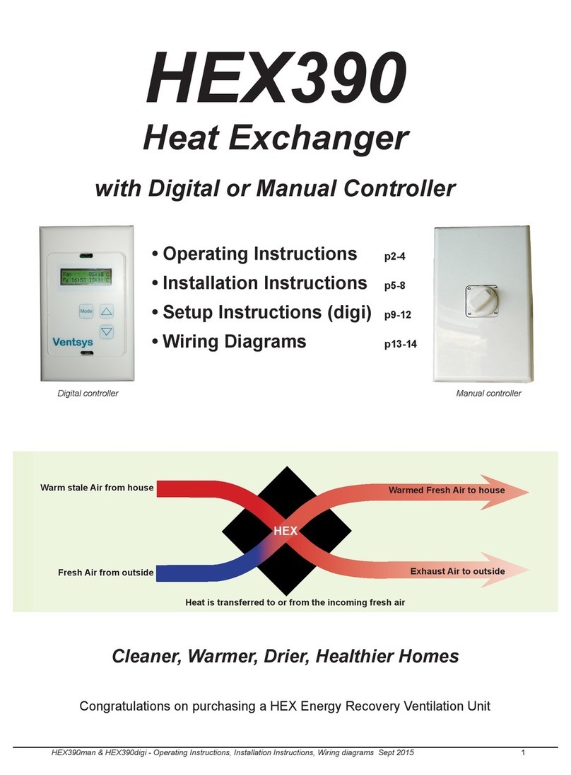
3 speed switch
User Operating Instructions
Manual Controller
This unit has High / Medium / Low speeds which the homeowner can use to regulate the
fresh air amount to suit the load. The 3 speed switch has four settings: Typically:
3 - High - where a number of people are living in the house and/or outside temperatures are
moderate
2 - Medium - less people in the house and/or colder outside temperatures
1 - Low - mainly to keep air fresh in the home during extremely cold conditions.
0 - Off
Fan Speed
Status
Outside Air
Temp(Δ)
Operating
Mode
Inside Air
Temp(□)
Fan Speed
Increase
Time
Fan Speed
Decrease
Mode
button
To get to User Menu: press and hold
mode button, continue holding while
until “User Setup” shows.
Use the up arrow to change the
options, Mode button to select.
Digital controller
Δ
□
This manual suits for next models
7
Table of contents
Other Smooth-Air Fan manuals
