Smooth-Air HEX390 m User manual

HEX390man & HEX390digi - Operating Instructions, Installation Instructions, Wiring diagrams Sept 2015
1
Warm stale Air from house
Fresh Air from outside
Warmed Fresh Air to house
Exhaust Air to outside
HEX
Heat is transferred to or from the incoming fresh air
HEX390
Heat Exchanger
with Digital or Manual Controller
Cleaner, Warmer, Drier, Healthier Homes
•Operating Instructions p2-4
•Installation Instructions p5-8
•Setup Instructions (digi) p9-12
•Wiring Diagrams p13-14
Congratulations on purchasing a HEX Energy Recovery Ventilation Unit
Draft
Manual controllerDigital controller

HEX390man & HEX390digi - Operating Instructions, Installation Instructions, Wiring diagrams Sept 2015
2
HEX
Operating Instructions
Cleaningtheunit’slters
The internal lters are designed as secondary lters (there should be
extended surface lters cleaning the air before reaching the unit). However,
when unit lters are heavily soiled, wash or replace the lter material.
To wash: use vacuum cleaner to remove excess dust, then wash in warm
detergent treated water, keep lters at or leave in frame to wash.
1
1
2
2
3
3
4
4
5
5
6
6
A A
B B
C C
D D
HRV ASSEMBLY
HEAT RECOVERY DESIGN
PROJECT
BEN MUNRO 18/02/2012
DESIGNED BY CHECKED BY APPROVED BY DATE
1 / 2
EDITION DRG. NO :
DATE MATERIAL
as
SCALE: 1:3
ALL DIMENSIONS IN mm
ALL DIMENSIONS +- 0.5mm UNLESS STATED
This is Smooth-Air Products copyright and contains proprietary owned
intellectual property rights and confidential data. All rights are strictly
reserved. The information must not be used except for the agreed
purpose. Unauthorised use, reproduction,or issue to any third party is not
permitted without the prior written authority of Smooth-Air Products. This
document is to be returned to Smooth-Air Products when the agreed
purpose is fulfilled.
DO NOT SCALE
391.5
343.0
263.0
754.5
600.5
90.3
PLAN VIEW
FRONT VIEW
ISOMETRIC VIEW
SIDE VIEW
Polymer cross ow
Heat Recovery core
Fans
Return Air
from house
Fresh Air
from outside
Supply Air to house
Exhaust Air to outside
Return Air lter
HEX unit
Supply Air
Return Air
Exhaust Air
Outside Air
The unit is designed to recover heat from exhaust air, which in turn warms (or
cools) the fresh outside air.
Supply Air lter
HEX390man & HEX390digi - Operating Instructions, Installation Instructions, Wiring diagrams Sept 2015
3
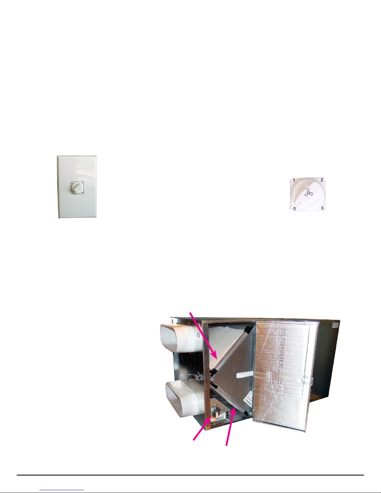
Return Air lter
Fresh Air lter
Optional
Internal On/Off
Thermostat
3 speed switch
3 speed switch
The 3 speed switch has four settings:
0 - Off
1 - Low
2 - Medium
3 - High
Manual Controller
User Operating Instructions
This unit has High / Medium / Low speeds which the homeowner can use to
regulate the fresh air amount to suit the load. Typically:
• High where a number of people are living in the house and/or outside
temperatures are moderate
• Medium less people in the house and/or colder outside temperatures
• Low mainly to keep air fresh in the home during extremely cold conditions.
Internal On/off thermostat (optional) For the manual controller, the
optional thermostat can be set so the unit turns off if incoming air exceeds
the set point (eg if thermostat is set to 30, the unit will turn off if the incoming
fresh air is above 30ºC).
HEX390man & HEX390digi - Operating Instructions, Installation Instructions, Wiring diagrams Sept 2015
4
• Optional User System On/Off is available in User Menu, indicated by “OFF”
on unit display.
• Optional Filter Timer measures the hours run by the fan and gives a ashing
display when the lter needs to be cleaned/replaced.
• Clock function has battery back-up in the event of a power failure. Time can
be set/adjusted by pressing mode and ↓ buttons together until “Entering
Menus” then “Set Clock” appears. Time can then be adjusted using up & down
buttons, once correct time is set, press “mode” to save new setting.
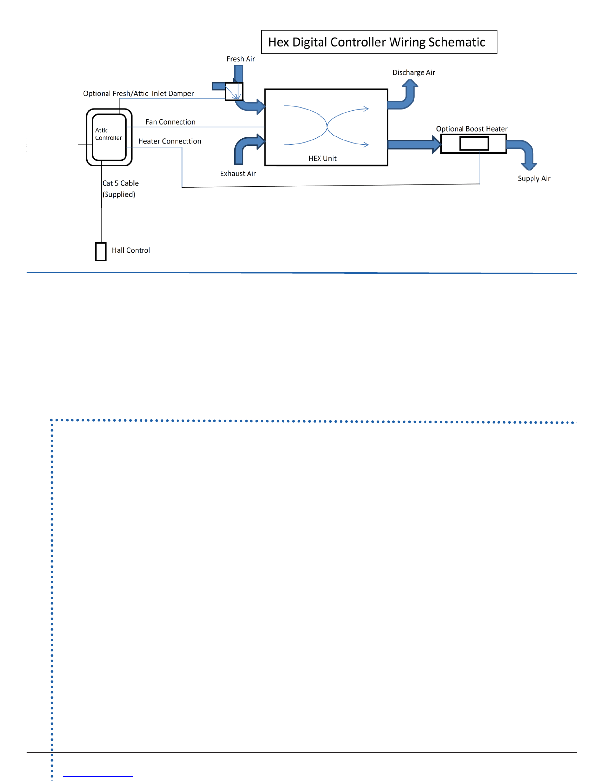
• Optional Attic Damper Kit. A diverting branch can be attached to divert the
intake from the attic to the cooler outside air. Press mode and up arrow
together. ‘Enteringmenus’ will display, hold until ‘Damper is on’ or ‘Damper is o’,
then ‘Change damper? ON’ or ‘Change damper? OFF’ displays. Use the up arrow to
change between the two settings.
Digital Controller
User Operating Instructions
Congratulations on purchasing a HEX, Heat Recovery Ventilator with Digital
Controller. This controller allows the user to adjust fan speed from high to low
(fan limits are set in the commissioning menu to suit the size of house and
system layout).
The controller will automatically shut down in summer if outside air temperature
(OS) exceeds 27°C and home is warm.
There are a number of other features available at time of installation which will
need to be discussed with the installer when the unit is commissioned (see Digital
Controller Setup instructions p6-9). They include:-
• Optional supply air boost
heater (when heater tted) is
controlled automatically when
outside air temp (OS) is less
than 12°C and home is cold.
This is indicated by “H” with
bar symbol in the unit display.
Heat is controlled over a
proportional band so that as
OS gets colder, heater output
increases to maximum.
• Optional winter off
mode shuts down the fan
automatically when outside
temperature (OS) is less than
2°C. This is indicated by
“winter” on the unit display.
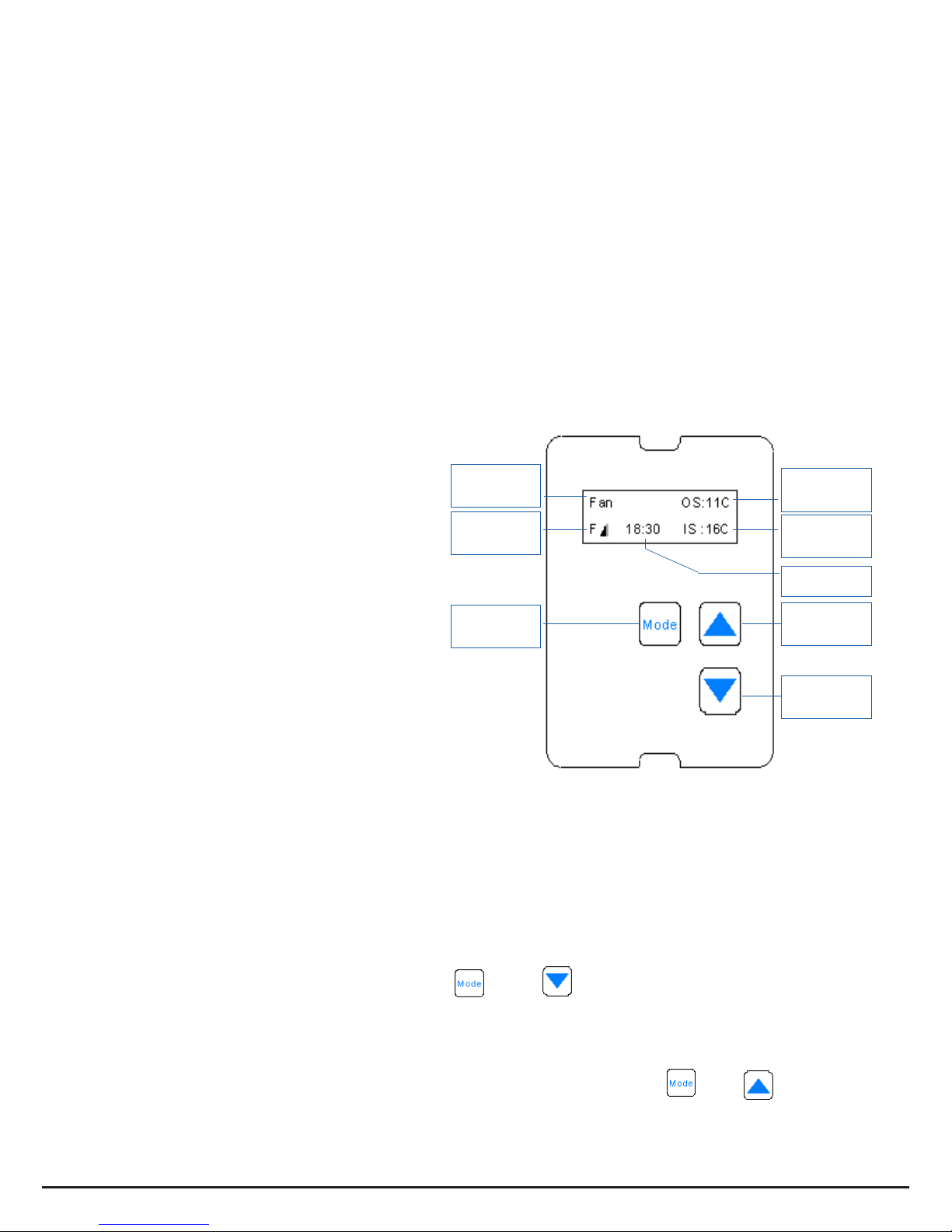
Fan Speed
Status
Outside Air
Temp (OS)
Operating
Mode
Inside Air
Temp (IS)
Fan Speed
Increase
Time
Fan Speed
Decrease
Mode
button
Heater option
not available for
HEXdigi-NH

HEX390man & HEX390digi - Operating Instructions, Installation Instructions, Wiring diagrams Sept 2015
5
Exhaust Air
Fresh Outside Air
Balanced Pressure Ventilation
Supply Air
Return Air
Key Benefits
• Better Climate Control
• Reduced heating load
• Reduced air-conditioning load
• Fresh air
• Energy efficiency
• Reduces condensation
HEX390
Installation Instructions
These units must be installed by a suitably qualied tradesperson.
Electrical supply must be installed by a suitably qualied electrician as per the
schematics on p13 (manual controller) and p14 & p15 (digital controller).
Supplied:
• HEX unit
• HEX attic box
• Triple rocker switch (inside attic box)
• Drain adaptor (inside HEX lter access door)
Required:
• Primary extended surface lters
• External inlet and outlet grilles
• Internal supply and return grilles
• Duct
• Tape
• 3 and 4 core wire
• Drain condensate hose
2. Mount Unit securely in ceiling space (eg use bungees to
hang, or anti-vibration pad) where it can be readily connected
to an electrical supply and is sufciently high enough above
the ceiling that a condensate drain can be run with a fall and
P-trap to a suitable outlet (see drain installation over page).
Once duct etc connected, unit needs to be level for drain to
work properly.
HEX hangers on
top of unit
1. Plan layout, check required equipment:

HEX390man & HEX390digi - Operating Instructions, Installation Instructions, Wiring diagrams Sept 2015
6
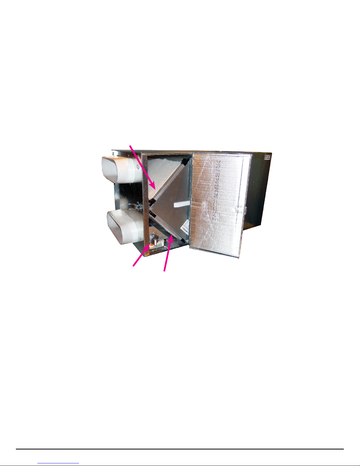
Exhaust Air
Return Air lter
Fresh Air lter
HEX body
Supply Air
Return Air
Outside Air
HEX
Drain
adaptor
P trap in condensate
drain hose
Drain Adaptor
Bottom of unit
Attach drain adaptor onto hole on base
of unit
4. External inlet and exhaust - Mount Fresh Air inlet and Exhaust Air discharge
away from each other, so that cross contamination is not possible, and as suits
the home owner.
5. Internal return and supply - Mount supply air grilles as suits the homeowner,
eg in the hallway and living areas. A hinged lter grille (eg PYHF400) can be
used for return air. Mount return air grilles as suits the homeowner, eg one in
the bathroom and one at the other end of the hall from supply grille.
6. Filters inside unit are secondary lters. Mount hinged lter grilles (eg
PYHF400) or extended surface lters (eg FBP200) in ducting prior to unit for
return air from house as well as fresh intake air.
3. Drain installation
Drain adaptor (supplied inside HEX lter
cover) is to be mounted to bottom of
HEX unit. HEX unit must be level.
Condensate drain hose
needs to be connected
and shaped into a “P
trap”, as in diagram:
7. Duct Attach insulated ducting to all spigots and Y branches securely, ensuring
an airtight seal by using tape. Duct runs must be stretched and as straight as
possible, with long radius bends to minimise airow resistance. Ducting must
be supported separately from the HEX unit. Ducts must be insulated.
HEX390man & HEX390digi - Operating Instructions, Installation Instructions, Wiring diagrams Sept 2015
7
Internal On/off thermostat (optional)
The optional thermostat can be set
so the unit turns off if incoming air
exceeds the set point (eg if thermostat
is set to 30, the unit will turn off if the
incoming fresh air is above 30ºC).
HEX Attic box
Temperature sensor
mounted in fresh air inlet
Temperature
sensor wire
plugs in here
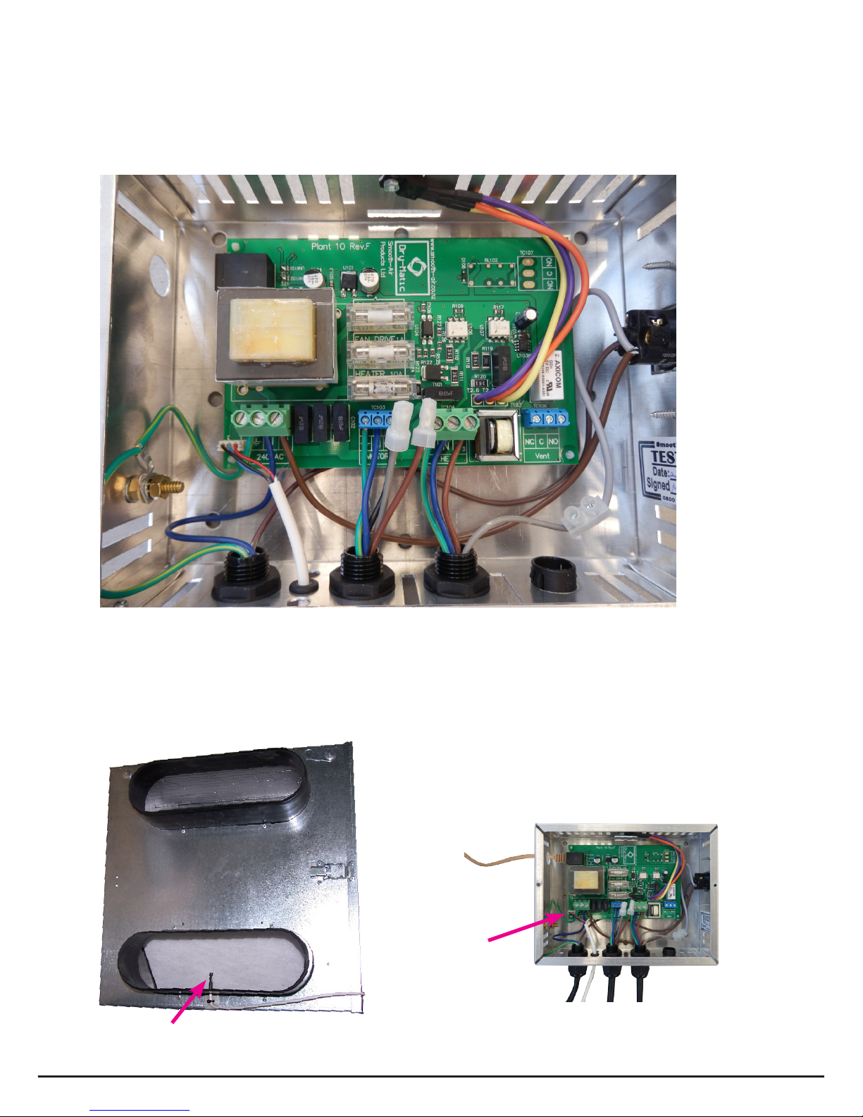
9. Thermostat for Digital Controller
The thermostat for the digital controller is placed into incoming fresh air ow,
through the pre-drilled hole, and xed with the cable tie.
It is then plugged into the attic box as pictured above.
Cat5 cable to digital
wall controller
For digital controller, mount
with pack glands downwards
Terminate
separately
the grey &
brown wires
from the
HEX unit
8. Mount Attic box
Attic box can be mounted on the unit or anywhere in the attic. The hall
controller - digital or manual 3 speed - will be shipped inside the attic box.
Electrical supply must be installed by a suitably qualied tradesperson
as per the schematics on pages 13, 14 & 15.
HEX390man & HEX390digi - Operating Instructions, Installation Instructions, Wiring diagrams Sept 2015
8
Heater option not available for HEXdigi-NH
11. Next step
Before commissioning the digital controller, consider the desired options
for the situation & write them down eg on p12
10a. Internal On/Off thermostat (optional) Digital Controller:
If there is an internal On/Off thermostat, this should be disabled for digital
controller, as the digital controller should control all airows.
10b. Internal On/Off thermostat (optional) Manual Controller:
The optional thermostat can be set so the unit turns off if incoming air
exceeds the set point (eg if thermostat is set to 30, the unit will turn off if
the incoming fresh air is above 30ºC).
Return Air lter
Fresh Air lter
Optional
Internal On/Off
Thermostat

HEX390man & HEX390digi - Operating Instructions, Installation Instructions, Wiring diagrams Sept 2015
9
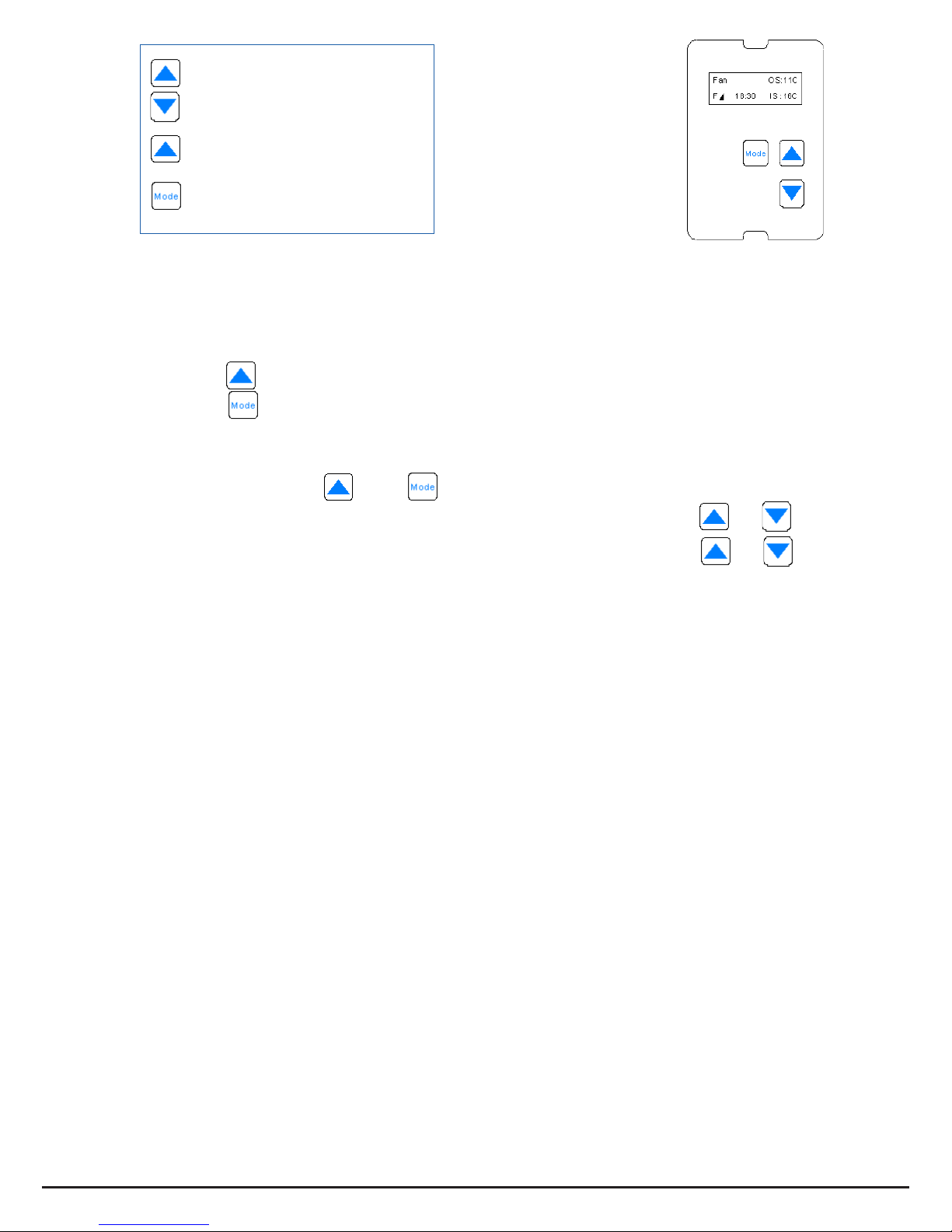
Display Key
OS - Outside Air Temperature
IS - Inside Air Temperature
Winter - winter mode is on
H - Heater is tted
Heater option not available for HEXdigi-NH
HEX
There are a number of options which can be scrolled through by
pressing the Mode button as below.
If no button is pressed within 5 seconds the controller automatically
reverts to normal operation. Once a button is pressed a backlight will
operate and remain on for 20 seconds after the last keystroke.
Press ↑ button to toggle between Y/N (Yes/No) or other options, then
press ‘Mode’ to advance through the menu.
Options are on following pages.
Digital Controller
Setup Instructions
The Heat Recovery Digital Controller has a number of features available to
customize the system to suit house size, layout and user preferences.
The Setup menu is accessed by pressing the ↑ & ↓ buttons together for
about 5 seconds until the display reads ‘Setup Menu’.
The controller comes preset with default factory settings, these can be
reinstated using menu item ‘Factory Reset’ (number 14 on next pages). If the
unit is not set up correctly to suit the house, performance may be reduced.
Fan Speed
Status
Outside Air
Temp (OS)
Operating
Mode
Inside Air
Temp (IS)
Fan Speed
Increase
[Y/Ntoggle]
Time
Fan Speed
Decrease
Mode
[to scroll]
Digital Controller setup instructions continued on next page
Please note: if settings are changed from recommendations, performance
of the unit may be reduced.
HEX390man & HEX390digi - Operating Instructions, Installation Instructions, Wiring diagrams Sept 2015
10
Press together 5 secs to get Setup Menu,
display will then change to:
1. Heater Kit Y/N (default N).
If N - heater options are removed from all menus.
If Y - heater options are available in User menu - Heater On/Off for
continuous or night heat (to times as set below) .
To set night heat option:
• press up arrow to select Y, then:
• press mode to display ‘Heater Times’ >display then changes
automatically to show the current settings (default: )
>display changes again to ‘Change Times’ Y/N (default N).
• At this point, use then to select Y & change the times.
• Select desired Heater ON time in Hours:Mins using or
• Select desired Heater OFF time in Hours:Mins using or
• Heater Test Y/N (default N)
• change to Y, heater test will be performed. If there are any faults
(including no heater connected), ‘Heater Fault’ will display. (See
menu item 4.Fan Speed Heat for possible Heater Fault causes.)
To reset Heater Fault display, turn unit off.
2. Max Fan Speed (default 100%) – Range is 10% to 100% adjustable in
10% increments using up & down arrows.
For a large house set to a max of 100%.
3. Min Fan Speed (default 10%) – Range is 10% to 100% adjustable in
10% increments using up & down arrows.
For a large house set to a min of 50%
4. Fan Speed Heat (default 50%) – Range is 10% to 100% adjustable in
10% increments using up & down arrows.
Fan Speed Heat sets a minimum speed for the fan to ensure
enough airow for the heater to operate. There are many duct fan
combinations, some more restrictive to airow than others. Therefore,
when setting up, the installer must check that the heater operates
without ‘Heater Fault’ ashing on the display. ‘Heater Fault’ is triggered
when the heater is operating but draws no current, this is most often
due to insufcient airow causing the airow proving switch to cut off.
If there is insufcient airow, increase the ‘Fan Speed Heat’ setting.
Heater fault may also be caused by manual reset thermal cutouts which
may need to be reset.
Heater ON 19:00
Heater OFF07:00
Heater option not available for HEXdigi-NH
Heater option not available for HEXdigi-NH
Use up arrow to change, then
mode to advance through menu
Use Mode button to scroll
through options
Press up and down arrows
together for 5 secs to get to
Setup Menu
Digital Controller setup instructions continued on next page

HEX390man & HEX390digi - Operating Instructions, Installation Instructions, Wiring diagrams Sept 2015
11
5. Winter Mode Y/N (default N). Winter mode shuts the system down when the
outside air temperature gets below eg 2°C. If Winter Mode is on, another menu
item will appear to allow adjustment of actual shut down temp: Range -2°C to
+5°C.
6. Filter Timer Y/N (default N) – Controller counts hours run by the fan and when
lter is due for a change the display ashes with ‘Filter’. If lter timer set Y,
another menu appears allowing lter period adjustment (240 day) (range 150
- 240 days). A further menu item will appear at user level once ltered timer
timed out, allowing timer to be reset once lters are cleaned or replaced.
7. I/Side Ref Temp (default 18°C) Range 16-24°C. This is the reference
temperature for the inside of the house, used for:
• Heating – when house temp (IS) is lower than 18°C (default) and outside
temp (OS) is lower than 12°C (default) the heater will operate (if tted).
• Summer – when house temp (IS) is higher than 18°C (default) and outside
temp (OS) is higher than 27°C (default) the unit will shut-down.
8. O/Side Ref Temp (default 12°C) Range 8-16°C. This is the reference
temperature for the outside air, below which heater operates (if tted).
9. O/Side Degree Offset (default 0°C) this allows unit to be calibrated in the
unlikely event that outside air temperature reads too high or low (adjustment
range -10°C to + 10°C).
10. I/Side Degree Offset (default 0°C) - As above.
11. Heat P/band (default 5°C) Range 1-7°C. Heat Proportional Band - When heater
is tted and conditions call for its operation, heater will start heating at 20%
when OS (outside) drops to reference temp (default 12°C), and will operate at
100% when temperature has dropped by a further (default) 5°C (ie when OS is
7°C).
12. Summer Temp S/down (default 27°C) Range 25°-35°C. When OS (outside
temp) is greater than 27°C and IS (inside temp) is greater than 18°C, the
system shuts down.
13. User Sys On/Off (default Off) - when On, user menu has option to turn system
On/Off.
14. Factory Reset Y/N (default N). Yes defaults all menu items to factory default
setting, these default settings are shown in brackets above.
Heater option not available for HEXdigi-NH
Heater option not available for HEXdigi-NH
Heater option not available for HEXdigi-NH
Heater option not available for HEXdigi-NH
Digital Controller setup instructions continued on next page
• Optional Attic Damper Kit. A diverting branch can be attached to divert
the intake from the cooler outside air to the attic. Press mode and up
arrow together until ‘Enteringmenus’ displays, hold until ‘Damper is on’or
‘Damper is o’ displays. ‘Change damper? ON’ or ‘Change damper? OFF’ then
displays. Use the up arrow to change between the two settings.

HEX390man & HEX390digi - Operating Instructions, Installation Instructions, Wiring diagrams Sept 2015
12
Installer’s recommended settings:
1. Heater Kit Y/N
Heater ON time: ........ : ........
Heater OFF time: ........ : ........
2. Max Fan Speed .......... %
3. Min Fan Speed .......... %
4. Fan Speed Heat .......... %
5. Winter Mode Y/N
If Y, shut down temp: .......... °C
6. Filter Timer Y/N
If lter timer Y: .......... days
7. I/Side Ref Temp .......... °C
8. O/Side Ref Temp .......... °C
9. O/Side Degree Offset .......... °C
10. I/Side Degree Offset .......... °C
11. Heat P/band .......... °C
12. Summer Temp S/down .......... °C
13. User Sys On/Off
14. Factory Reset Y/N
• Optional attic damper kit installed Y/N
Installer Details:
Heater option not available for HEXdigi-NH
Heater option not available for HEXdigi-NH
Heater option not available for HEXdigi-NH

HEX390man & HEX390digi - Operating Instructions, Installation Instructions, Wiring diagrams Sept 2015
13
Wiring for manual 3speed switch
The attic box also comes with
a two core wire for use with the
optional thermostat.

HEX390man & HEX390digi - Operating Instructions, Installation Instructions, Wiring diagrams Sept 2015
14
Wiring for HEX digital controller
Heater option
not available for
HEXdigi-NH
PN P1N P3
NNCC
240VAC MOTOR HEAT Vent
Circuit Board
Patch lead socket
Isolator
Switch.
NO
Heat Sensor Plug.
Grey (HT15D Only)
Green
Blue
Brown
Grey
Mode
Dry-Matic
Fan
Diverting
Branch
Motor
Heater
1
2
3
N P
PN
If damper operates in "reverse"
change CW<>CCW switch on
motor body to correct.
For digital controller, mount attic box
with pack glands downwards
Supplied cable for the
duct heater for
HT07 is three core.
HT15 is four core
- wire to earth, P3 & N.
Note wiring connection
details supplied with
heater.
Attic Controller
(for HT15 only)
Heater (for HT07 &HT15)
Optional
Attic damper kit
1
2
3
PN P1N P3
NNCC
240VAC MOTOR HEAT Vent
Circuit Board
Patch lead socket
Isolator
Switch.
NO
Heat Sensor Plug.
Grey (HT15D Only)
Green
Blue
Brown
Grey
Mode
Dry-Matic
Fan
Diverting
Branch
Motor
Heater
1
2
3
N P
PN
If damper operates in "reverse"
change CW<>CCW switch on
motor body to correct.
Diverting
branch motor
Hall controller
For heated units only
Heat
sensor
For attic damper kit, ensure the heat
sensor is in duct, upstream of lter box.
High
Medium Terminate
Terminate
E
Black
Brown
Grey
Blue
Grn/Yel
Basic HEXbody wiring to attic box
Supplied cable for the fan unit is
ve core - wire to N & P1
(HT15 only)
N
E
P1
Low
N
HEX unit
Terminate
seperately
Cable for electrical
supply is three core
and pre-wired to
the attic controller.
NO NC
See p7 for full
image
Terminate grey
& brown wires
from the HEX
unit separately
HEX390man & HEX390digi - Operating Instructions, Installation Instructions, Wiring diagrams Sept 2015
15
WARRANTY RETURN
Upon installation, please send to the manufacturer, c/o PO Box 8358, Christchurch
(on request by the dealer).
Purchaser: ___________________________________ ________________________
Address: _______________________________________________________________
Description: HEX390 ____________________________________________________
Purchased from / Dealer: ___________________________________________________
Dealer invoice number: ____________________________________________________
Date of installation: ________________________________________________________
Installed by: _____________________________________________________________
HEXdigi Attic box wiring diagram
Heater option not available
for HEXdigi-NH
HEX Warranty
24 months manufacturing warranty from date of rst retail purchase.
This HEX product, when delivered to you in new condition from a HEX authorized dealer
and used in normal conditions, will be free from any defects in manufacturing, materials
and workmanship for the periods set out above (“Warranty Period”):
Any faulty goods will be repaired or replaced via the HEX dealer.
This warranty is for the manufactured product, it does not include installation or removal.
Electrical
Supply
230VAC
by installer

HEX390man & HEX390digi - Operating Instructions, Installation Instructions, Wiring diagrams Sept 2015
16
Warm stale Air from house
Fresh Air from outside
Warmed Fresh Air to house
Exhaust Air to outside
HEX
Heat is transferred to or from the incoming fresh air
Display Key
OS - Outside Air Temperature
IS - Inside Air Temperature
Winter - Winter mode is on
H - Heater is tted
Fan Speed
Status
Outside Air
Temp (OS)
Operating
Mode
Inside Air
Temp (IS)
Fan Speed
Increase
[Y/Ntoggle]
Time
Fan Speed
Decrease
Mode
[to scroll]
Heater option not available for HEXdigi-NH
This manual suits for next models
1
Table of contents
Other Smooth-Air Fan manuals


Popular Fan manuals by other brands

Greenheck
Greenheck AMPLIFY DS Installation, operation and maintenance manual

Wolf
Wolf DV-2 Installation and operation instructions

Fanimation
Fanimation The Zonix FP4640 owner's manual

YitaHome
YitaHome TLCFLS-0008 Assembly instructions

Schuller
Schuller VITO 218047 installation guide

Suntec Wellness
Suntec Wellness Klimatronic CoolBreeze 2000 TV manual


