SN3 Innovations DS-FX9 User manual

SN3 Innovations, LLC
DS-FX9 User Guide
DS-FX9 User Guide
Patent Pending

2
MAY 2017 DS-FX9 USER GUIDE
Acknowledgements
Initiated and released by the SN3 Innovations, LLC team, this document was developed with
support from across the company and in direct collaboration with the following:
Key Contributors
Greg Notaro, MSEE (SN3)
Technical Reviewers
T. Scott Notaro, MS, MBA (SN3)
Doug Notaro, PhD (SN3)
Feedback
Please send comments or suggestions about this document to the SN3 Innovations, LLC Team
SN3 Innovations, LLC designs advanced entertainment lighting equipment for use by a broad array of
customers. Ease-of-use is the primary focal point in the company’s development strategies and is achieved
by incorporating novel design concepts and technically advanced solutions that alleviate operational
challenges associated with current products on the market.
www.sn3innovations.com
Disclaimer
The information and specifications contained in this document are subject to change without notice. SN3
Innovations, LLC assumes no liability or responsibility for any errors or omissions that may appear within.
SN3 Innovations, LLC reserves the right to update the existing document to correct for any errors or to add
additional content. The latest version of this document can be found and downloaded from
www.sn3innovations.com
Legal Notice
Complying with all applicable copyright laws is the responsibility of the user. Without limiting the rights
under copyright, no part of this document may be reproduced, stored in or introduced into a retrieval
system, or transmitted in any form or by any means (electronic, mechanical, photocopying, recording, or
otherwise), or for any purpose, without the express written permission of SN3 Innovations, LLC.
SN3 Innovations, LLC may have patents, patent applications, trademarks, copyrights, or other intellectual
property rights covering subject matter in this document. Except as expressly provided in any written
license agreement from SN3 Innovations, LLC, the furnishing of this document does not give you any
license to these patents, trademarks, copyrights, or other intellectual property.
© 2017 SN3 Innovations, LLC. All rights reserved.
SN3 Innovations, LLC, The Diamond Series, are trademarks of SN3 Innovations, LLC
All other trademarks are property of their respective owners.
3
DS-FX9 USER GUIDE MAY 2017
Revision and Signoff Sheet
Change Record
Date
Author
Version
Change reference
3/22/2016
Greg Notaro
-
Initial draft
5/17/2016
Greg Notaro
-1
Update DMX control features, detail breakout of system
6/1/2016
Greg Notaro
-2
Disclaimer, Safety, Mechanical information, updated technical notes
4/6/2017
Greg Notaro
-3
Capture final DMX user information
5/13/2017
Greg Notaro
-4
DMX Table updates prior to product release
Reviewers
Name
Version approved
Position
Date
Autumn Notaro
-4
Doug Notaro
-4
Director
T.Scott Notaro
-4
President
Distribution / Signoff
Name
Position
T. Scott Notaro
President
Doug Notaro
Director
Greg Notaro
Vice President

4
MAY 2017 DS-FX9 USER GUIDE
Table of Contents
Tables................................................................................................................... 5
Figures ................................................................................................................. 5
Safety................................................................................................................... 6
FCC Compliance ..................................................................................................... 7
Product Specifications ............................................................................................. 8
Mechanical ........................................................................................................... 8
Light Source ......................................................................................................... 9
Power.................................................................................................................. 9
User Interface........................................................................................................ 9
Lighting Zones ....................................................................................................... 9
Stand-Alone Operational Modes ...............................................................................11
Automatic Synchronization (Master/Slave) ................................................................11
DS-FX9 Display - Automatic Sync .......................................................................... 12
DMX512-A Control .................................................................................................12
Standard DMX512-A Link...................................................................................... 12
Proprietary Enhancement to DMX512-A .................................................................. 13
DMX512-A Control using Standard Equipment ......................................................... 14
DS-FX9 Application Recommendation .......................................................................15
DMX Operational Modes..........................................................................................16
Audio/Manual Effect Trigger Control .........................................................................18
DMX Data.............................................................................................................20
Warranty..............................................................................................................28
References & Contact Information............................................................................28

5
DS-FX9 USER GUIDE MAY 2017
Tables
Table 1 - FCC Testing Method/Standard Results ............................................................... 7
Table 2 - DS-FX9 Operational Modes: Determined by DMX Slot 1 Data Byte....................... 15
Table 3 - DMX Operational Mode (DMX Personality) –Slot 1 ............................................ 20
Table 4 - 3-Channel Synchronization ............................................................................ 21
Table 5 - 48-Channel Synchronization .......................................................................... 21
Table 6 - 432-Channel Synchronization......................................................................... 22
Table 7 - 48-Channel Synchronization Program.............................................................. 23
Table 8 - 432-Channel Synchronization Program ............................................................ 24
Table 9 - Free Running ............................................................................................... 25
Table 10 - Free Running RGB Color Selection................................................................. 25
Table 11 - Auto Address Tri-Color Device Mode .............................................................. 26
Table 12 - Auto Address Tri-Color Block Mode................................................................ 26
Table 13 - RESERVED - 1............................................................................................ 27
Table 14 - RESERVED - 2............................................................................................ 27
Figures
Figure 1 –DS-FX9 Front ............................................................................................... 8
Figure 2 - DS-FX9 Back ................................................................................................ 8
Figure 3 –144 Tri-Color LED Reference Designators ....................................................... 10
Figure 4 –36 Channel Configuration (9 Lighting Zones / Blocks) ...................................... 10
Figure 5 –4-Way Slide Switch (Located on Back Panel)................................................... 11
Figure 6 –DS-FX9 Display –DMX Connections............................................................... 12
Figure 7 –DMX connection from Master to "n" Slave devices. (n <= 32) ........................... 13
Figure 8 –DMX control arrangement example: 5 DMX fixtures operating in 3Chn DMX mode 13
Figure 9 –DS-FX9’s electrical interface. Point-to-Point RS-485 communication .................. 14
Figure 10 –Typical DS-FX9 Application –(n) DS-FX9 devices controlled by a standard DMX
Controller ................................................................................................................. 14
Figure 11 –DMX512-A Packet: Slot 1 Data Byte selects the DS-FX9 Operational Mode ........ 15
Figure 12 –Audio/Manual Effect Trigger Control............................................................. 19

6
MAY 2017 DS-FX9 USER GUIDE
Safety
•If mounting this product from a truss, on an elevated platform, or by any means
overhead, always secure to a fastening device using a safety cable.
•To reduce the risk of electrical shock or fire, do not expose this unit or the external
power supply to rain or moisture.
•This product is for indoor use only.
•Make sure that the mains supply matches that of the required voltage of the
external power supply.
•Do not attempt to operate this unit if the power cord of the external supply has
been broken, frayed, or damaged in any way.
•Disconnect from mains power before making any electrical connections to the unit.
•Do not attempt to remove the cover or operate when the cover is removed.
•Disconnect the external power supply from mains power when the device is
experiencing long durations of non-use.
•Do not plug the external supply into a dimmer pack.
•This fixture should only be serviced by qualified service personnel when damaged in
any way, including the external power supply.
•This product is not intended for permanent installations.
•Never attempt to carry the product from any connected electrical cable.
•Some people may experience severe dizziness, seizures, epileptic seizures or
blackouts triggered by flashing lights or patterns. Such seizures are more common
in children and young adults under the age of 20. Anyone who has a history of
seizures, loss of awareness, or other symptoms linked to an epileptic condition
should consult with a doctor before using this product.
•This product should not be operated by children under the age of 13. Any child
above the age of 13 attempting to operate this device should be monitored by an
adult.

7
DS-FX9 USER GUIDE MAY 2017
FCC Compliance
The DS-FX9 has been fully tested under the FCC Rules contained in Title 47 of the CFR, Part
15 Subpart B & Industry Canada ICES-003 for Class B Digital Devices.
All tests were conducted using measurement procedure from ANSI C.63.4.2009 as
appropriate.
Table 1 - FCC TESTING METHOD/STANDARD RESULTS
NOTE: This equipment has been tested and found to comply with the limits of Part 15 of the
FCC Rules. These limits are designed to provide reasonable protection against harmful
interference in a residential installation. This equipment generates, uses and can radiate radio
frequency energy and, if not installed and used in accordance with the instructions, may cause
harmful interference to radio communications. However, there is no guarantee that
interference will not occur in a particular installation. If this equipment does cause harmful
interference to radio or television reception, which can be determined by turning the
equipment off and on, the user is encouraged to try to correct the interference by one or more
of the following measures:
•Reorient or relocate the receiving antenna.
•Increase the separation between the equipment and receiver.
•Connect the equipment into an outlet on a circuit different from that to which the
receiver is connected.
•Consult the dealer or an experienced radio/TV technician for help.

8
MAY 2017 DS-FX9 USER GUIDE
Product Specifications
Figure 2 - DS-FX9 Back
Mechanical
Weight: 18 lbs
Dimensions: 19.5” x 19.5” x 4” (length x width x depth)
Note: Internal Mounting plate is included for O-ring attachment. O-ring mounting plate sold
separately. Contact SN3 Innovations, LLC for requests.
Figure 1 –DS-FX9 Front

9
DS-FX9 USER GUIDE MAY 2017
Light Source
144 (tri-color) 5mm RGB Diffused LEDs
Light Intensity: 4000mcd per LED
Viewing Angle: 65°
Life Span: 100,000+ hours (1000-hour Life Test per JIS C 7035 - 0/100 failures)
Power
The DS-FX9 requires the use of the supplied +5VDC power supply to operate. It is the
customer’s responsibility to use the power supply provided with the DS-FX9. Any attempt to
power the DS-FX9 from a supply not provided by SN3 Innovations, LLC will immediately void
the warranty.
Power Supply model: FY0507500
Input: 100-240VAC
Output: +5VDC, 7.5A, 37.5W
AC Cable: US 2-Prong 1.2M
AC Inlet Type: C8 Type DC 20AWG 1.5M
DC Tip Size: 5.5mm OD, 2.1mm ID Female
User Interface
The back panel of the DS-FX9 contains all necessary user interfaces.
1. Power input Jack –Mates with provided +5VDC power supply
2. DMX In –3-pin XLR Male
3. DMX Out –3-pin XLR Female
4. 4-Position Slide Switch –Used to select one of four operational modes when not
being controlled via DMX.
Lighting Zones
The DS-FX9 contains 144 tri-color LEDs. Under DMX control the user has the option of
addressing each LED pixel or partitioning the DS-FX9 into a subset of addressable lighting
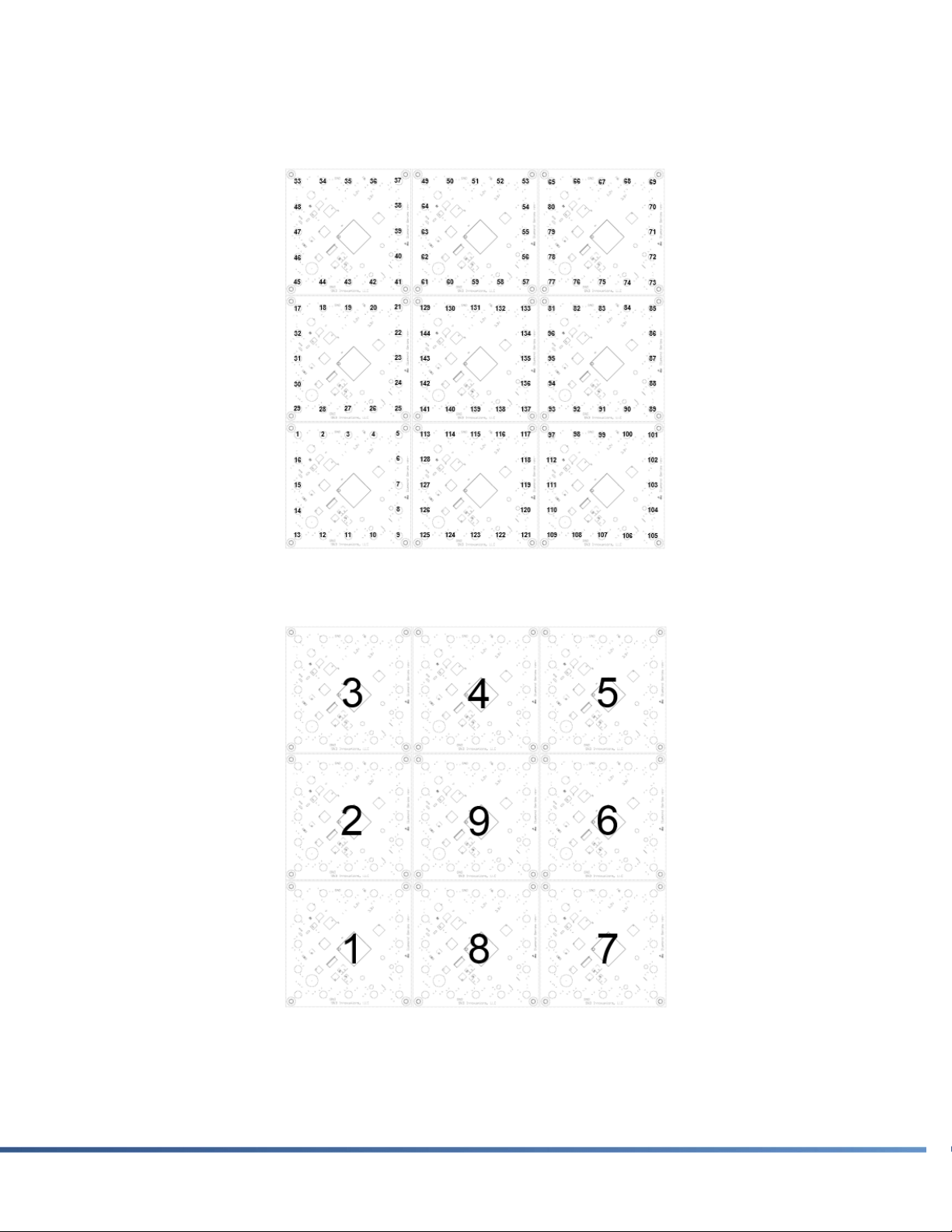
zones/Blocks. The possible LED controllable configurations are as follows:
1. 432 Channels –Each of the 144 tri-color LEDs can be addressed, each requiring
an individual RGB color assignment. See DMX Operational Modes.
2. 48 channels –Each of the 16 tri-color LEDs in each block can be addressed. All
nine blocks will operate in sync. Reference designators for the 16 tri-color LEDS
are the same as LEDs 1-16 shown in Figure 3.
3. 36 Channels –The DS-FX9 can be partitioned into 9 lighting zones (Blocks), each
requiring a specific RGBW color assignment. ‘W’ is reserved. See DMX Operational
Modes.
10
MAY 2017 DS-FX9 USER GUIDE
4. 4 Channels –The DS-FX9 can operate as a tri-color fixture (one lighting zone),
requiring an RGBW color assignment. ‘W’ is reserved. See DMX Operational Modes
Figure 3 –144 TRI-COLOR LED REFERENCE DESIGNATORS
Figure 4 –36 CHANNEL CONFIGURATION (9 LIGHTING ZONES /BLOCKS)
11
DS-FX9 USER GUIDE MAY 2017
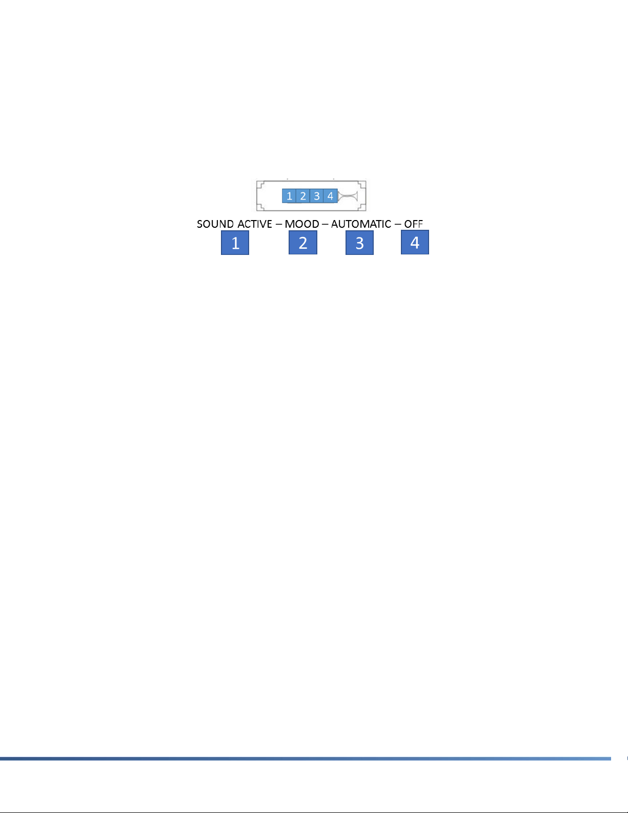
Stand-Alone Operational Modes
Four operational modes have been made accessible via a 4-way slide switch onboard the unit.
When no DMX control signal is present at the “DMX In” port, the DS-FX9 will automatically
operate in the user selected mode, dictated by the state of the 4-way slide switch. These four
operational modes are a small subset of the internal control functions and additional
operational modes of the device. Accessing these additional features requires the use of an
external DMX controller.
Figure 5 –4-WAY SLIDE SWITCH (LOCATED ON BACK PANEL)
ONBOARD OPERATIONAL MODES
1. Sound Active –The DS-FX9 will trigger internal lighting effects to the sound of the
music. Audio frequency content picked up by the onboard electret microphone will
be used to trigger time altering lighting effects.
2. Mood Lighting –All 144 LEDs will simultaneously sweep through a large subset of
colors from the color wheel. Any and all audio signals will be ignored in this mode.
3. Automatic –The DS-FX9 will cycle through the large quantity of internal lighting
effects applying different RGB color combinations for every repetitive cycle. Effects
will be continuously cycled. Any and all audio signals will be ignored in this mode.
4. Off –The DS-FX9 will be commanded to a Blank state. All LEDs will be off.
NOTE: Master/Slave synchronization occurs under any of the four onboard operational
modes discussed in this section when not using external DMX512-A control. Any DS-
FX9 device connected to this main unit will automatically synchronize.
Automatic Synchronization (Master/Slave)
Unlike traditional DMX intelligent fixtures, the DS-FX9 doesn’t require a specific Master/Slave
configuration in order to synchronize. DS-FX9 devices automatically communicate with other
units from the same product family without any DMX addressing or specific mode settings.
The steps required to accomplish a synchronized DS-FX9 display without any external DMX
control is very straight forward.
12
MAY 2017 DS-FX9 USER GUIDE
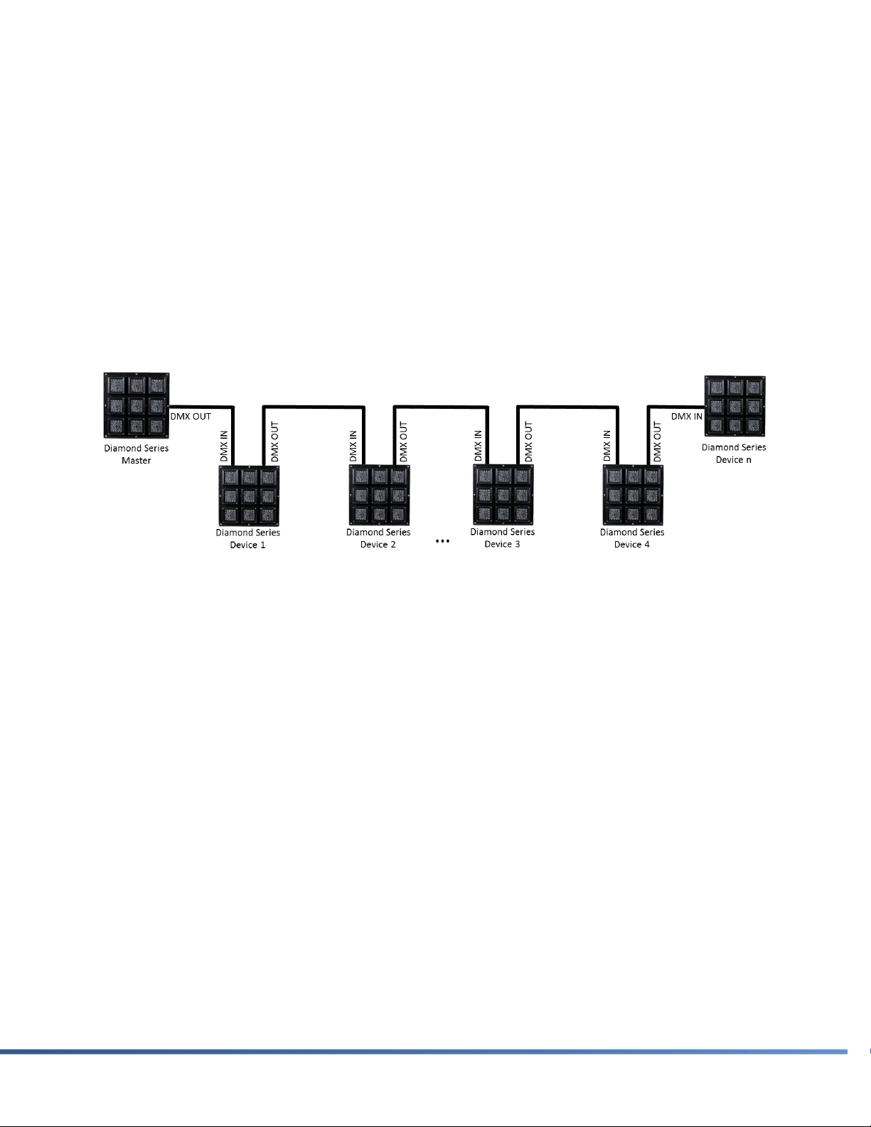
DS-FX9 Display - Automatic Sync
DS-FX9 DISPLAY CONNECTION STEPS (NO EXTERNAL DMX CONTROL)
1. Identify a master DS-FX9.
2. Set your master DS-FX9 to the desired stand-alone operational mode.
3. Using a DMX cable, connect the “DMX Out” from your master DS-FX9 to the “DMX In”
of your first DS-FX9 slave.
4. Using a second DMX cable, connect the “DMX Out” from your first slave DS-FX9 to the
“DMX In” of your second DS-FX9 slave.
5. Continue applying step #4 for as many slave DS-FX9 units you have in your display.
6. Apply power to each DS-FX9.
DMX512-A Control
The DS-FX9 has a multitude of internal operational features that can only be accessed via
DMX512-A control. Unlike traditional DMX intelligent fixtures, the DS-FX9 doesn’t require any
manual DMX Addressing, DMX Personality settings, or Master/Slave configuration. These
fixtures are able to operate without these added burdens due to a proprietary communication
enhancement that encapsulates the DMX512-A protocol. This enhancement provides the
ability of controlling an entire chain of DS-FX9 units operating in Master/Slave mode with a
DMX512-A controller. Switching from a Master/Slave operational mode to a DMX mode is
seamless and can be accomplished directly from a DMX512-A controller. This capability is
very unique. An understanding of how this approach differs from traditional DMX-512A
implementations is outlined in the following sections.
Standard DMX512-A Link
Traditional DMX512-A employs an RS-485 signaling standard and relies on a multi-drop
configuration to route the data to all devices in a network. Unlike many RS-485 applications,
DMX is a unidirectional control protocol which means data is transmitted from a single device
and received by all other devices. Bi-directional communication is not part of the DMX512-A
Figure 6 –DS-FX9 DISPLAY –DMX CONNECTIONS
13
DS-FX9 USER GUIDE MAY 2017
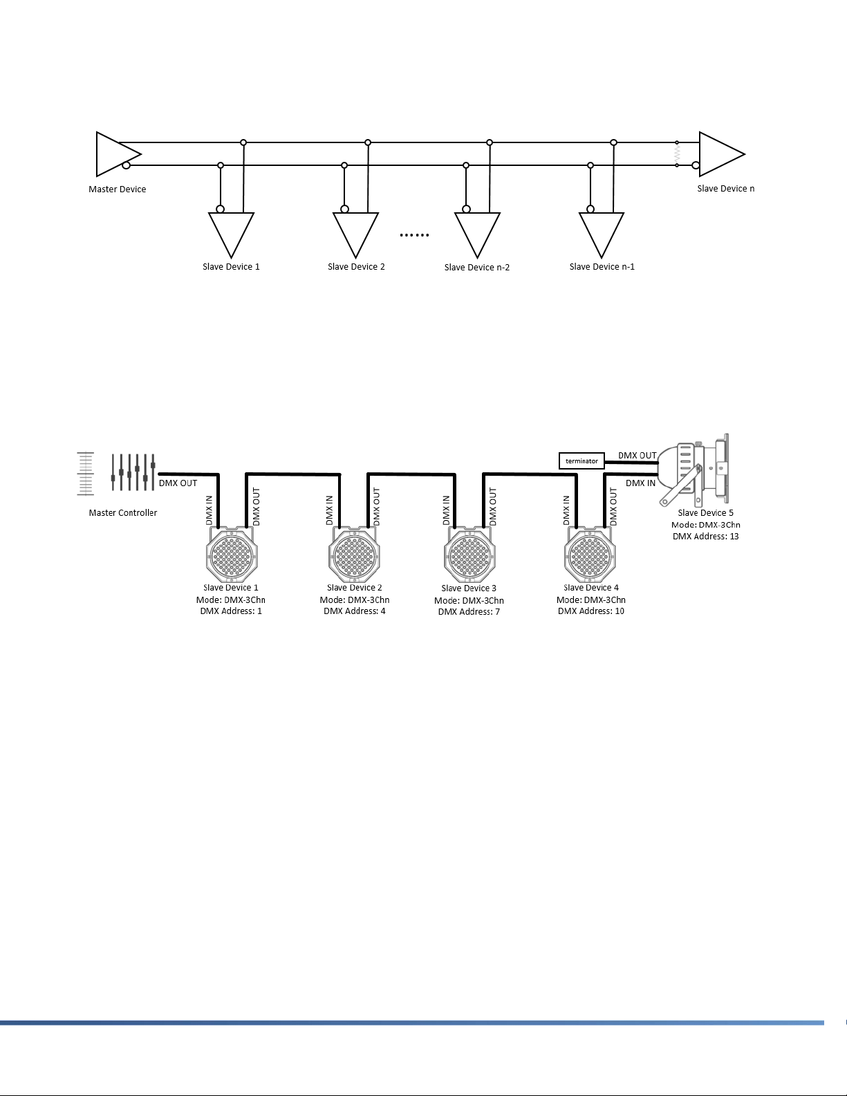
standard. A typical DMX connection from master to "n" number of slave devices is depicted
below:
Figure 7 –DMX CONNECTION FROM MASTER TO "N"SLAVE DEVICES.(N <= 32)
This lower level depiction of a DMX link is how all DMX intelligent fixtures operate. In order to
demonstrate this more clearly, we can look at a typical lighting display example. A user
incorporating a DMX controller to communicate to a fixed number of units is a very standard
and understood application and can be illustrated as follows:
Figure 8 –DMX CONTROL ARRANGEMENT EXAMPLE:5DMX FIXTURES OPERATING IN 3CHN DMX MODE
The above example illustrates a typical DMX application where each intelligent fixture requires
a specific DMX Address in conjunction with an appropriate DMX Personality setting. Notice a
terminator is also properly installed in order to maximize signal integrity. With this setup a
user can successfully transmit DMX data from his/her master controller and control each
fixture according to the manufacturer’s operational capabilities when assigned a 3Chn DMX
Personality.
Proprietary Enhancement to DMX512-A
The DS-FX9 operates differently. Instead of employing a standard multi-drop RS-485
network, a Point-to-Point RS-485 link is utilized.

14
MAY 2017 DS-FX9 USER GUIDE
Figure 9 –DS-FX9’S ELECTRICAL INTERFACE.POINT-TO-POINT RS-485 COMMUNICATION
The lower level electrical details don’t need to be an area of focus here but an important
concept needs to be addressed. Each DS-FX9 unit has the ability of modifying an incoming
DMX packet prior to transmitting the modified data out to the next unit. This capability is not
possible with a traditional DMX512-A link. It’s this concept that allows for the advanced
functionality of the DS-FX9.
Figure 10 –TYPICAL DS-FX9 APPLICATION –(N)DS-FX9 DEVICES CONTROLLED BY A STANDARD DMX
CONTROLLER
Note: When utilizing the DS-FX9 an external DMX terminator is not required. The DMX In
port includes a differential AC termination.
DMX512-A Control using Standard Equipment
As stated previously, the DS-FX9 contains an abundance of internal operational modes that
can be controlled via a standard DMX512-A controller. Any standard controller that conforms
to the ESTA DMX512-A specification can control the DS-FX9.
Setting the DS-FX9 Operational Mode (DMX Personality) via DMX
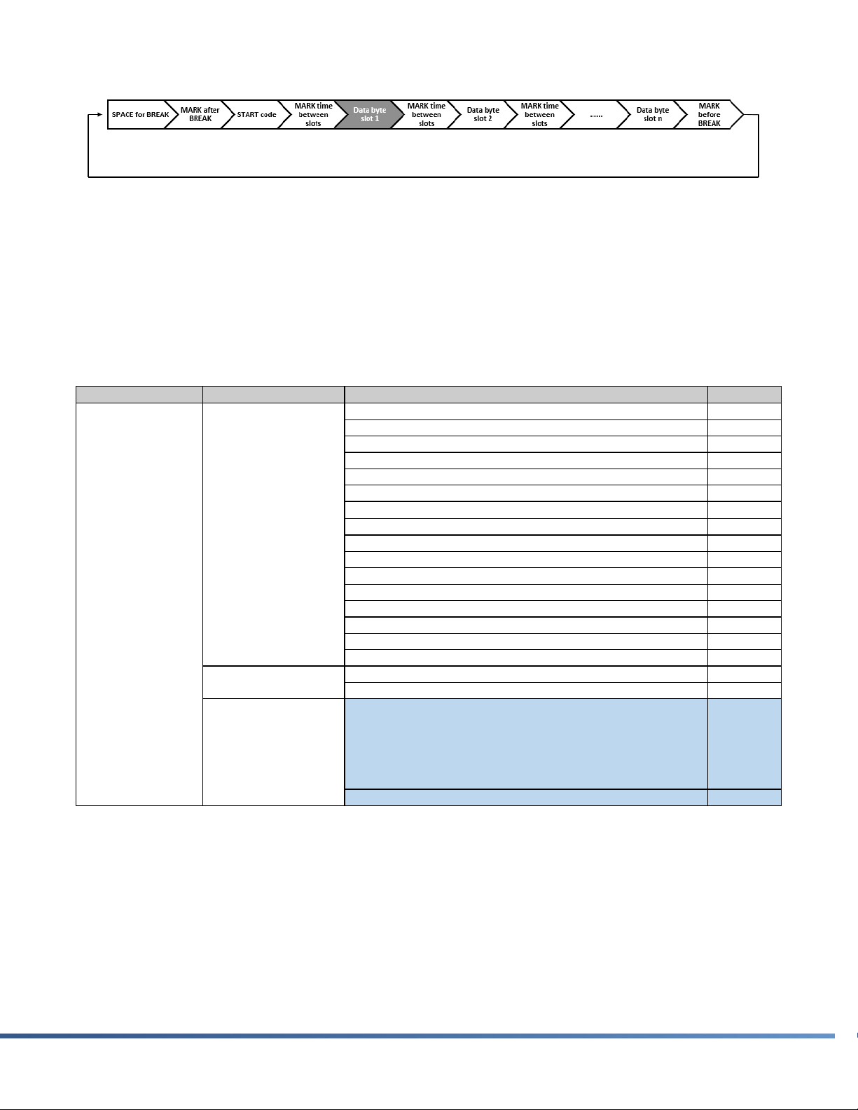
Commanding the DS-FX9 into a specific operational mode is done utilizing the Slot 1 data byte
in a DMX packet. A standard DMX512-A data packet can be represented in block form:
15
DS-FX9 USER GUIDE MAY 2017
Figure 11 –DMX512-A PACKET:SLOT 1DATA BYTE SELECTS THE DS-FX9 OPERATIONAL MODE
A typical DMX packet, with a maximum of 512 total DMX slots in a fully populated DMX
Universe, can be sent to the DS-FX9. The Slot 1 value is what dictates the operational mode
of the first DS-FX9 that receives the DMX packet. All subsequent DS-FX9 units, connected off
of this master unit, will receive intentionally modified DMX data. How the first DS-FX9 in the
link interprets and modifies the DMX data is strictly related to the operational mode. The
operational modes available to the DS-FX9 are listed in the following table:
Table 2 - DS-FX9 OPERATIONAL MODES:DETERMINED BY DMX SLOT 1DATA BYTE
DS-FX9 Application Recommendation
Due to the proprietary nature of how the DS-FX9 handles DMX communications, it is advised
to place your DS-FX9 devices on their own dedicated DMX Universe. Placing a DS-FX9 Master
along with another manufacturer’s intelligent lighting fixture as a Slave on the same DMX
Universe is possible. However, in order to accomplish this successfully, a thorough
DMX-512AChannel Category Mode Value
3-Channel Synchronization 000 ↔ 10
48-Channel Synchronization 11 ↔ 20
432-Channel Synchronization 21 ↔ 24
48-Channel Synchronization Program – Automatic 31 ↔ 40
48-Channel Synchronization Program – Sound Active 41 ↔ 50
48-Channel Synchronization Program – Bass Active 51 ↔ 60
432-Channel Synchronization Program – Automatic 61 ↔ 64
432-Channel Synchronization Program – Sound Active 71 ↔ 74
432-Channel Synchronization Program – Bass Active 81 ↔ 84
Free Running – Automatic 91 ↔ 100
Free Running – Sound Active 101 ↔ 110
Free Running – Bass Active 111 ↔ 120
Free Running – Mood Lighting 121 ↔ 130
Free Running RGB color selection – Automatic 131 ↔ 140
Free Running RGB color selection – Sound Active 141 ↔ 150
Free Running RGB color selection – Bass Active 151 ↔ 160
Auto Address Tri-Color Device Mode 161 ↔ 170
Auto Address Tri-Color Block Mode 171 ↔ 180
RESERVED-1
25 ↔ 30
65 ↔ 70
75 ↔ 80
85 ↔ 90
191 ↔ 255
RESERVED-2 181 ↔ 190
1
DMXControllable
Master/Slave
Modes
Address Free
DMXModes
RESERVED

16
MAY 2017 DS-FX9 USER GUIDE
understanding of the DS-FX9 Operational Modes is essential. Remember, DMX data is altered
within the DS-FX9, transmitting revised DMX data via the “DMX Out” port. A more robust
solution would be to incorporate a separate dedicated DMX Universe for other manufacturer’s
units.
DMX Operational Modes
There are two primary categories of DMX modes available within the DS-FX9:
DMX Controllable Master/Slave Modes
All connected units will synchronize as-is common with Master/Slave operation. However,
DMX control is available allowing the adjustment of certain operational parameters as well as
the ability of changing Master/Slave modes.
Address Free DMX Modes
Typical DMX control features allowing the user to adjust colors of individual units and LEDs.
No DMX addressing is required and the DMX personality is set automatically based on the
chosen Address Free DMX Mode.
DMX Controllable Master/Slave Modes:
3-Channel Synchronization: “DMX In” slots 2 –4 are used as the only RGB color
assignment for the DS-FX9. The entire DS-FX9 operates as a single tri-color device in
this mode. The DS-FX9 will transmit out a decimal value of 23 for Slot 1 (432-Channel
Synchronization). Slots 2 –433 will contain RGB color information for all 144 tri-color
LEDs contained within the DS-FX9. The RGB color values will be identical to what was
received at “DMX In”. Any DS-FX9 device connected as a slave will respond in sync.
48-Channel Synchronization: “DMX In” slots 2 –49 are used to address the 16 tri-
color LEDs of a single block (9 blocks total in the DS-FX9). Each block of the DS-FX9
will respond identically. “DMX Out” slots 2 –49 will contain identical data as “DMX In”.
Any DS-FX9 device connected as a slave will respond in sync.
432-Channel Synchronization: “DMX In” slots 2 – 433 are used to address the 144
tri-color LEDs of the DS-FX9. “DMX Out” slots 2 –433 will contain identical data as
“DMX In.” Any DS-FX9 device connected as a slave will respond in sync.
48-Chanel Synchronization Program (Automatic, Sound Active, or Bass
Active): “DMX In” slot 2 is used to select an internal 48-Chn program (see DMX data
section). “DMX In” slot 5 is used to enable manual DMX triggering. “DMX In” slot 6 is
the DMX Trigger and is only used when manual DMX triggering is enabled. The DS-FX9
will run a specific internal effects program based on the value of slot 2. “DMX Out” slot
1 is set to 48-Channel Synchronization. “DMX Out” slots 2 – 49 vary depending on the
internal program selected. DMX triggering is possible under Sound Active and Bass
Active modes. See DMX Data section. Any DS-FX9 device connected as a slave will
respond in sync.

17
DS-FX9 USER GUIDE MAY 2017
432-Channel Synchronization Program (Automatic, Sound Active, or Bass
Active): “DMX In” slot 2 is used to select an internal 432-Chn program (see DMX data
section). “DMX In” slot 5 is used to enable manual DMX triggering. “DMX In” slot 6 is
the DMX Trigger and is only used when manual DMX triggering is enabled. The DS-FX9
will run a specific internal effects program based on the value of slot 2. “DMX Out” slot
1 is set to 432-Channel Synchronization. “DMX Out” slots 2 – 433 vary depending on
the internal program selected. DMX triggering is possible under Sound Active and Bass
Active modes. See DMX Data section. Any DS-FX9 device connected as a slave will
respond in sync.
Free Running (Automatic, Sound Active, or Bass Active): The DS-FX9 will run in
either Automatic, Sound Active, or Bass Active mode based on the slot 1 value (see
DMX data section). “DMX In” slot 5 is used to enable manual DMX triggering. “DMX
In” slot 6 is the DMX Trigger and is only used when manual DMX triggering is enabled.
“DMX Out” will vary depending upon the internal effect running but Slot 1 will be set to
one of the three Synchronization modes. Any DS-FX9 device connected as a slave will
respond in sync.
Free Running (Mood Lighting): The DS-FX9 will operate in Mood Lighting mode and
will not react to any DMX triggering or microphone input. “DMX Out” will be set to 48-
Channel Synchronization. “DMX Out” slots 2 – 49 will vary depending upon the mood
color at the time. Any DS-FX9 device connected as a slave will respond in sync.
Free Running RGB Color Selection (Automatic, Sound Active, or Bass Active):
This mode is identical to the Free Running mode in Automatic, Sound Active, and Bass
Active operation. However, additional control is offered via “DMX In” slots 2 – 4. “DMX
In” slots 2 – 4 are used to assign a RGB primary color to the free running mode. The
DS-FX9 will utilize this RGB color as a primary color for all effects. All other functioning
is equivalent to the standard Free Running mode. DMX triggering is possible under
Sound Active and Bass Active modes. See DMX Data section. Any DS-FX9 device
connected as a slave will respond in sync.
Address Free DMX Modes:
Auto Address Tri-Color Device Mode: This mode is used to automatically address a
series of DS-FX9 units on a single DMX Universe in 3-chn RGB mode. Note, a fourth
channel is held in reserve and is ignored by the DS-FX9. “DMX In” slot 2 is used to
assign an offset. This offset is used to indicate which RGB color values listed in the
DMX packet the first DS-FX9 needs to grab. An offset decimal value of 0 tells the first
DS-FX9 to utilize slots 3 - 5 for its RGB color assignment. An offset decimal value of 4
tells the DS-FX9 to utilize slots 7 –9 for its RGB color assignment. The same logic
applies for other offset values. The DS-FX9 will remove all slot values leading up to its
assigned offset value, not including slots 1 and 2, before transmitting data out. “DMX
Out” Slot 1 will remain in Auto Address Tri-Color Device Mode. “DMX Out” Slot 2
continues to hold the offset value. However, the DS-FX9 will automatically set this
offset value to a value of 4.

18
MAY 2017 DS-FX9 USER GUIDE
Auto Address Tri-Color Block Mode: This mode is used to automatically address all
Blocks of a series of DS-FX9 units on a single DMX Universe. “DMX In” slot 2 is used to
assign an offset. This offset is used to indicate which RGB color values listed in the
DMX packet the DS-FX9 unit needs to grab. An offset decimal value of 0 tells the first
DS-FX9 to utilize slots 3 - 36 for the subsequent RGB values of each of its 9 Blocks. An
offset decimal value of 36 tells the DS-FX9 to utilize slots 39 –74. The same logic
applies for other offset values. The DS-FX9 will remove all slot values leading up to its
assigned offset value, not including slots 1 and 2, before transmitting data out. “DMX
Out” Slot 1 will remain in Auto Address Tri-Color Block Mode. “DMX Out” Slot 2
continues to hold the offset value. However, the DS-FX9 will automatically set this
offset value to a value of 36.
RESERVED-1: The DS-FX9 will blank its LEDs in this mode. “DMX Out” will be identical
to the data received at the “DMX In” port. Therefore, the device will simply act as a
DMX repeater.
RESERVED-2: The DS-FX9 will blank its LEDs in this mode. “DMX Out” will be identical
to the data received at the “DMX In” port with one caveat: The slot 1 value will be
changed to a decimal value of 195.
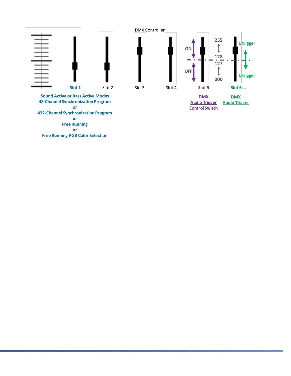
Audio/Manual Effect Trigger Control
A very unique and useful control feature of the DS-FX9 is the ability to trigger and alter effects
remotely via DMX control. This feature allows a multitude of options such as the ability to
synchronize the DS-FX9 effects to a BPM extractor available in many lighting and DJ oriented
software packages or manually trigger and alter effects from a DMX consol. Taking advantage
of this feature is very simple and only requires the use of six DMX channels.
When configured in a mode capable of audio trigger control, two DMX channels (Slot 5 and
Slot 6) are used to enable and control this function. To enable manual triggering, Slot 5 needs
to be set to a value greater than or equal to 128. Once enabled, Slot 6 is used to send
triggers to the DS-FX9. A single trigger is sent when Slot 6 is within the following ranges:
0 <= Slot 6 <= 127 or 128 <= Slot 6 <= 255. Once a trigger is sent, the Slot 6 value must
change to a value within the alternate acceptable range. A graphical representation of this
control is shown below.
19
DS-FX9 USER GUIDE MAY 2017
Figure 12 –AUDIO/MANUAL EFFECT TRIGGER CONTROL
Each trigger will enable and/or alter the behavior of the DS-FX9 effect causing a very distinct
and recognizable visual change.
20
MAY 2017 DS-FX9 USER GUIDE
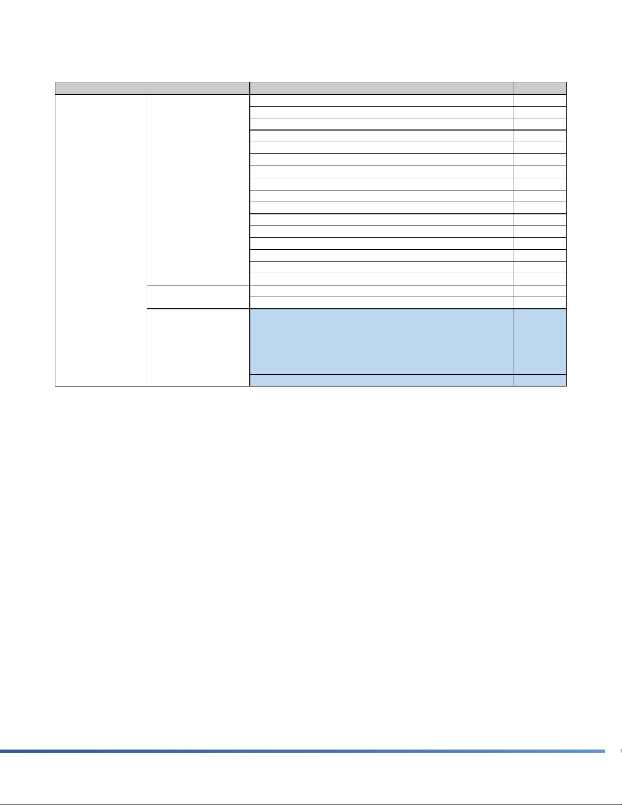
DMX Data
Table 3 - DMX OPERATIONAL MODE (DMX PERSONALITY)–SLOT 1
DMX-512AChannel Category Mode Value
3-Channel Synchronization 000 ↔ 10
48-Channel Synchronization 11 ↔ 20
432-Channel Synchronization 21 ↔ 24
48-Channel Synchronization Program – Automatic 31 ↔ 40
48-Channel Synchronization Program – Sound Active 41 ↔ 50
48-Channel Synchronization Program – Bass Active 51 ↔ 60
432-Channel Synchronization Program – Automatic 61 ↔ 64
432-Channel Synchronization Program – Sound Active 71 ↔ 74
432-Channel Synchronization Program – Bass Active 81 ↔ 84
Free Running – Automatic 91 ↔ 100
Free Running – Sound Active 101 ↔ 110
Free Running – Bass Active 111 ↔ 120
Free Running – Mood Lighting 121 ↔ 130
Free Running RGB color selection – Automatic 131 ↔ 140
Free Running RGB color selection – Sound Active 141 ↔ 150
Free Running RGB color selection – Bass Active 151 ↔ 160
Auto Address Tri-Color Device Mode 161 ↔ 170
Auto Address Tri-Color Block Mode 171 ↔ 180
RESERVED-1
25 ↔ 30
65 ↔ 70
75 ↔ 80
85 ↔ 90
191 ↔ 255
RESERVED-2 181 ↔ 190
1
DMXControllable
Master/Slave
Modes
Address Free
DMXModes
RESERVED
Table of contents
Popular Lighting Equipment manuals by other brands


CREE LIGHTING
CREE LIGHTING Stylus Series installation instructions

DOTLUX
DOTLUX 3942-027IP205M user manual

ProLights
ProLights DISPLAYCOBTRWDDY2 user manual

Enlite
Enlite EN-BA1222 installation instructions

Godox
Godox ML30 instruction manual

Daintree
Daintree GE current Immersion GELP24-100U-GLX installation guide

Onstate Technologies
Onstate Technologies PCBA Series technical information

Satco
Satco NUCO 62-1580 Installation and safety instructions

Lightolier
Lightolier Lighting Systems LP-13 Specification sheet

Briloner
Briloner MAL 1384 Mounting instructions

Platek
Platek MINI ONE Assembly instructions

Griven
Griven MicroParade user manual