Snap Appliance Snap Disk 30SA User manual

Quick Start Guide and User CD
Kurzanleitung und Benutzer-CD
Guía de iniciación rápida y CD del usuario
Guide de mise en route rapide et CD de l’utilisateur
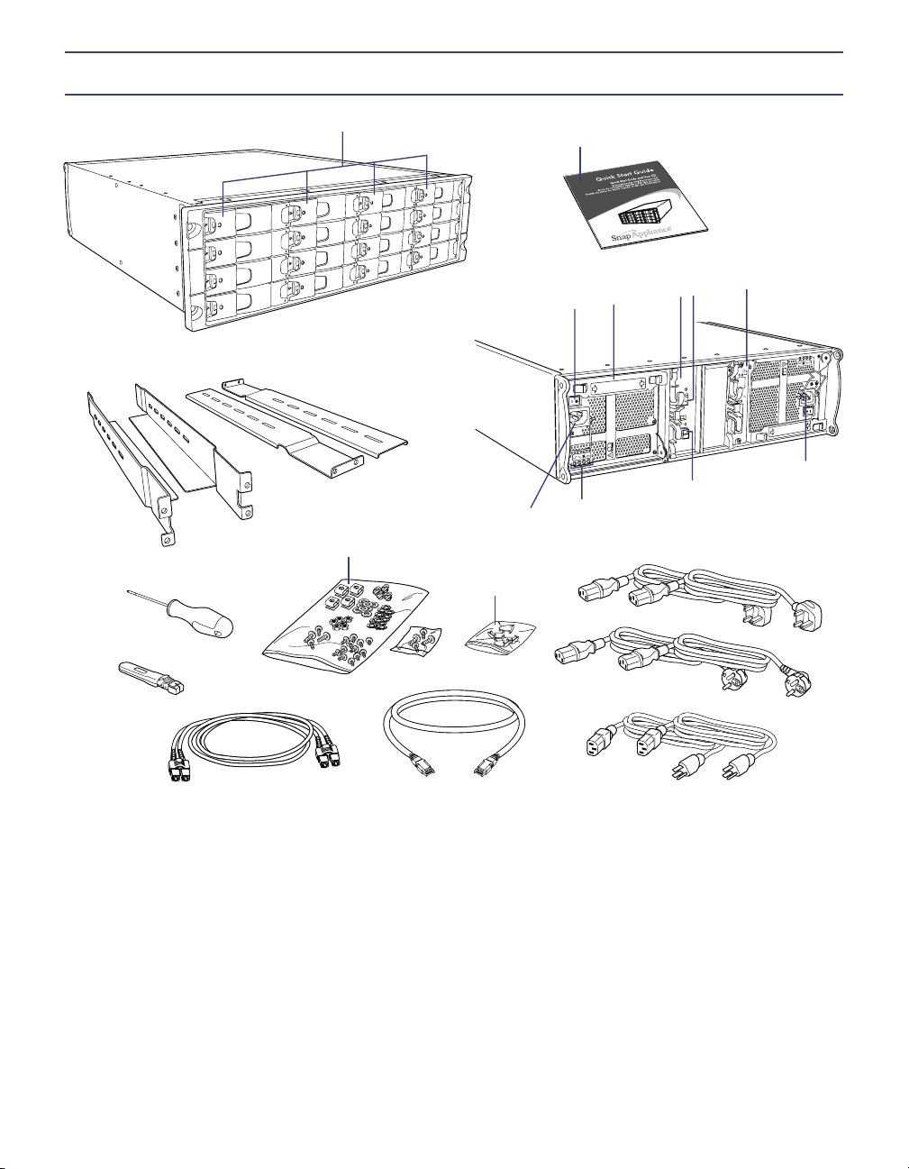
Hardware Features
1 Hot-swappable disk drives (sixteen) 7 Optical FC connector 13 Power connector
2 Quick Start Guide 8 FC Address module 14 Power/Fan module status lights
3 Rack mount shelves 9 Disk drive locking tool 15 Copper FC connector
4 Power/Fan module power switch 10 FC loopback terminator 16 Optical FC cable
5 Power/Fan module 11 Rack mount screws 17 Copper FC cable
6 Controller module 12 Bezel screw covers (four) 18 Power cables
12
3
45678
9
10
11
12
13
13
14 15
16 17
18
About This Guide
The Snap Disk™ 30SA storage subsystem is a 3U expansion array with sixteen Serial ATA disk drives and two
bre channel (FC) connectors. A Snap Disk 30SA’s capacity is only available through the head Snap Server®
(packaged and shipped seperately) to which it is connected; no direct network cabling is possible. Use this guide
in conjunction with the guide that accompanied your head Snap Server to set up your storage system.
Overview
Every Snap Disk 30SA ships with a 3 meter optical FC cable, a 1meter copper FC cable, and one optical FC
loopback terminator. Multiple Snap Disk 30SAs can be connected to a Snap Server in a single loop conguration.
Connections The Snap Disk 30SA controller module has an optical FC connector (OPTICAL), a copper FC
connector (COPPER), an internal terminator (TERM) switch, and a Fault light. Expansion arrays are daisy chained
using the provided cables, alternating between the optical and the copper cables (see illustration opposite).
Termination To close the loop, the nal Snap Disk 30SA in your installation must be properly terminated.
Termination is achieved in the nal expansion array either by setting the TERM switch in the ON position or by
connecting the optical bre channel loopback terminator.
Addressing When connecting multiple Snap Disk 30SAs, each array must be uniquely identied to the FC-HBA
card. Enclosure IDs are set by rotating the ID wheel on the FC Address module. The wheel is incremented by using
a small pointed object to press the button on the top or bottom of the wheel.
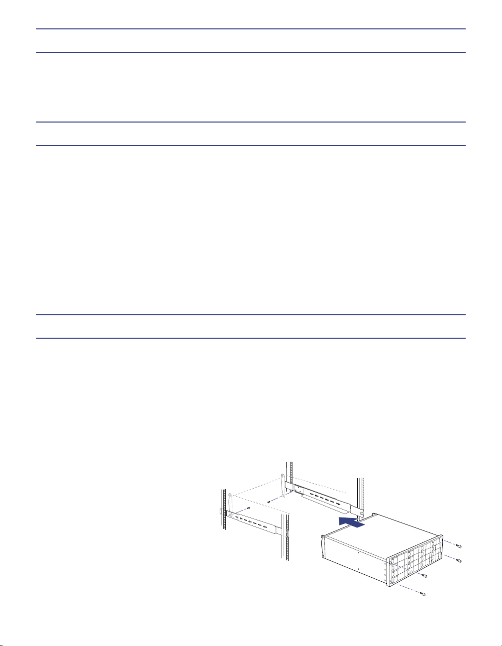
Rack Installation
Each Snap Disk 30SA ships with two adjustable (left and right) rack mount shelves and a packet of screws for
attaching the server to a four-post rack. Each shelf consists of two rails, one containing the shelf itself and the
other serving as a support. To safely install the server, you will also need a Phillips screwdriver, a nut driver, and
an assistant to help in installing the expansion array into the rack.
Tip When daisy chaining multiple Snap Disk 30SAs to a Snap Server, the units must be mounted on the same
rack due to the length restriction of the bre channel cables.
1 Adjust the length of the shelf and support rails to roughly the proper length for the rack into which you are
mounting the Snap Disk 30SA.
2 Use up to three screws per side to loosly attach the shelf to
the extender.
3 Using the four screws provided, securely
attach the ends of the shelf assemblies to the
rack posts as shown, and then tighten the
screws securing the two arms of the shelf
assembly together.
4 With help from an assistant, slide the Snap Disk
30SA onto the shelves and attach the four mounting
screws to the rack posts through the holes in the anges.
Apply the plastic covers to the screw holes.
5 Repeat this procedure for any additional Snap Disk 30SAs to be installed.

Connecting the First Snap Disk 30SA to a Snap Server
Caution Use only the Snap Appliance cables provided. DO NOT use any other cable to connect the expansion
arrays; data integrity and throughput will be seriously impacted.
1 Connect one end of the optical FC cable to the FC connector at the rear of the Snap Server, and the other end
to the OPTICAL connector on the Snap Disk 30SA.
2 If installing a single Snap Disk 30SA, make sure the terminator (TERM) switch is in the ON position, and then
check the ID and Dip Switch settings as described below. If installing additional units, make sure the TERM
switch is in the OFF position and proceed to the next section.
Connecting Additional Snap Disk 30SAs
1 Connect additional units, alternating between the optical and the copper cables. For example:
• To connect a second Snap Disk 30SA, connect one end of the copper
FC cable to the COPPER connector at the rear of the rst Snap Disk
30SA, and then connect the other end to the COPPER connector at
the rear of the second Snap Disk 30SA.
• To connect a third Snap Disk 30SA, connect one end of the optical
FC cable to the OPTICAL connector at the rear of the second
Snap Disk 30SA, and then connect the other end to the OPTICAL
connector at the rear of the third Snap Disk 30SA.
2 When all Snap Disk 30SAs are connected, make sure the loop is
properly terminated. Do one of the following:
• If the nal connection is made on the last Snap Disk 30SA with a
copper cable, make sure the TERM switch is in the OFF position
and insert the bre channel loopback terminator into the
OPTICAL connector of the last Snap Disk 30SA.
• If the nal connection is made with an optical cable, make sure that
TERM switch is in the ON position.
3 On all intermediate arrays, make sure the TERM switch is in the OFF
position.
Conguring the Enclosure ID
Each expansion array attached to the Snap Server must have a unique enclosure ID. Pressing the top button
decrements the number; pressing the bottom button increments the number.
The rst expansion array must have an ID of 1 (one). On
additional expansion arrays the enclosure ID must be
incremented by one, as shown in the above illustration.
Tip The dip switches (located below the ID selector) are
preset at the factory to ensure SD30 connectivity to the host
Snap Server. DO NOT modify the dip switch settings from
their defaults.
ID
Copyright © 2004 Snap Appliance, Inc. All rights reserved worldwide.
All other product names or company names are the property of their
respective owners.
Copyright © 2004 Snap Appliance, Inc. Alle Rechte weltweit
vorbehalten. Alle anderen Produktnamen und Firmennamen sind
Eigentum der jeweiligen Unternehmen.
Copyright © 2004 Snap Appliance, Inc. Reservados todos los derechos
en el ámbito internacional. Todos los otros nombres de productos o de
compañías son propiedad de susrespectivos propietarios.
Copyright © 2004 Snap Appliance, Inc. Tous droits réservés dans
le monde entier. Tous les autres noms de produit ou de société
appartiennent à leurs détenteurs respectifs.
Snap Appliance
2001 Logic Drive
San Jose, CA 95124 USA
888.310.SNAP (7627)
www.snapappliance.com
70990687-002 Rev. A
Connecting the Power Cords
As a data integrity measure, Snap Appliance strongly recommends connecting both the Snap Server and any
Snap Disk 30SAs to a power source via the same UPS device. Plug the power cords (female end) into the power
connectors on the Snap Disk 30SA. Plug the other end (male end) of each power cord into a UPS (recommended)
or properly grounded electrical outlet.
Powering On the Snap Disk 30SA
The host Snap Server must be powered down before you can initialize a Snap Disk 30SA. After the host
Snap Server is powered down, switch on the power modules (two per array) of each Snap Disk 30SA. An array
is ready when the disk drive lights on the front of the chassis stop ashing and remain solid green (about 10 to 15
seconds). After all arrays are ready, power on the Snap Server.
Verifying that the Snap Disk 30SA is Online
By default, the SD30SA’s disk drives are not congured as members of a RAID, and will appear as unassigned
disk drives in the browser-based Administration Tool.
1 Launch a Web browser and enter the server name or IP address of the Snap Server to which the SD30SA is
connected.
2 Click the Administration link and log in as the administrator.
3 Navigate to the Storage > Devices screen.
An expansion array’s disk drives are distinguished from those of the host Snap Server by the label EXTN. For
example, the drives of the rst connected array are labeled EXTN1, the drives of the second array EXTN2, and
so on.
Table of contents
Other Snap Appliance Storage manuals


