Snap-on Equipment EELR591A User manual

1 of 84
EAZ0080V42A
Snap-on Equipment
INSTALLATION AND OPERATING MANUAL
READ THOROUGHLY BEFORE INSTALLING,
SERVICING OR MAINTAINING THE
LIFT.
SAVE THIS MANUAL
INSTALLATION and OPERATION MANUAL
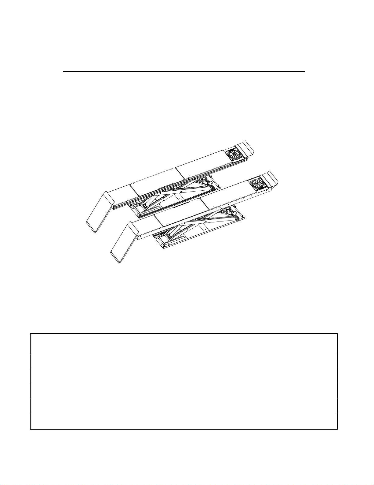
14K SCISSOR LIFT
Standard Models:
EELR591A, EELR592A, EELR593A, EELR594A
EELR787A, EELR788A, EELR789A, EELR790A
Short Models:
EELR587A, EELR588A, EELR589A, EELR590A
EELR783A, EELR784A, EELR785A, EELR786A
Apr 2020 REV. J
309 EXCHANGE AVENUE, CONWAY, ARKANSAS, 72032
TEL: 501-450-1500, FAX: 501-450-1585

2 of 84
TABLE OF CONTENTS
1.0 OWNER / EMPLOYER OBLIGATIONS ......................................................... 4
2.0 IMPORTANT SAFETY INSTRUCTIONS ....................................................... 4
3.0 SAFETY WARNING DECALS ....................................................................... 7
4.0 SPECIFICATIONS ......................................................................................... 8
5.0 CONTENTS .................................................................................................. 10
6.0 TOOLS REQUIRED FOR INSTALLATION OF LIFT .................................. 10
7.0 INSTALLATION OVERVIEW ....................................................................... 11
8.0 INSTRUCTIONS ........................................................................................... 11
8.1 Flushmount Bay Layout ..................................................................... 12
8.2 Surfacemount Bay Layout ................................................................ 13
8.3 Baseframe Location ........................................................................... 14
8.4 Anchor Location ................................................................................. 15
8.5 Unpacking the Lift .............................................................................. 16
8.6 Hydraulic Connections....................................................................... 17
8.7 Air Safety and Auxiliary Air connections ........................................ 19
8.8 Pneumatic Sensor Connections ........................................................ 23
8.9 Electrical Connections ....................................................................... 25
8.10 Initial Operation ................................................................................ 27
8.11 Equalizing Function Check ............................................................. 28
8.12 Maximum Height Adjustment ......................................................... 29
8.13 Level and Support ............................................................................ 30
8.14 Anchoring Procedure ....................................................................... 31
8.15 Grouting Procedure (Optional) ........................................................ 32
9.0 ACCESSORY INSTALLATION .................................................................... 33
9.1 Installation of Line Covers ................................................................. 36
9.2 Installation of Extension Line Covers ............................................... 37
10.0 LOCKING FRONT TURNPLATES & REAR SLIP PLATES (OPTIONAL) 38
10.1 Installation of Front Turnplates ...................................................... 38
10.2 Console Connections for Locking & Lights .................................. 40
11.0 FINAL PROCEDURES ............................................................................... 42
11.1 Check of Assembled Lift .................................................................. 42
11.2 Operation Test with Vehicle ............................................................. 42
12.0 LIFT OPERATION ...................................................................................... 43
12.1 Raising the Lift .................................................................................. 43
12.2 Lowering the Lift ............................................................................... 43
13.0 RECOMMENDED MAINTENANCE ........................................................... 44
13.1 Checking Oil Level for Air Lubricator ............................................ 44
13.2 Maintenance of Turnplate & Slip Plate Locking System (Opt.) .... 45
14.0 LOCK OUT AND TAG OUT INSTRUCTIONS .......................................... 47
14.1 Isolation and Verification Procedure: ............................................ 48

3 of 84
14.2 Emergency Operation ...................................................................... 49
15.0 TROUBLE SHOOTING ............................................................................. 52
16.0 RECORD OF MAINTENANCE / TRAINING ............................................. 53
17.0 LIFT ASSEMBLY ....................................................................................... 55
17.1 Lift Assembly Parts List ................................................................... 55
18.0 REAR SLIP PLATE TRANSFER BALL ARRANGEMENT ....................... 60
19.0 HYDRAULIC & AIR ASSEMBLY ............................................................... 61
19.1 Hydraulic & Air Parts List ............................................................... 61
19.2 VARIOUS POLYTUBES .................................................................... 62
19.3 POLYTUBE PARTS LIST ................................................................. 62
19.4 OPTIONAL: LIGHT KIT SENSOR PARTS LIST ............................. 63
20.0 ACCESSORY ASSEMBLY ........................................................................ 64
20.1 Front Turnplate ................................................................................. 64
20.2 Rear Slip Plate Locking Mechanism .............................................. 66
20.3 Airline Routing for Locking Turnplates and Rear Slip Plates ...... 67
20.4 Rear LED Light Assembly: Exploded View ................................... 69
20.5 LED CONTROL BOX ......................................................................... 71
21.0 CONSOLE ASSEMBLY ............................................................................. 72
21.1 Electrical Panel ................................................................................. 72
21.2 Terminal Assembly for 14K ALI Console........................................ 73
21.3 Console: Pneumatic & Filtering System ........................................ 74
21.4 Console: Pneumatic & Filtering System -
Locking & Light System (Optional) ................................................ 75
21.5 Control Panel .................................................................................... 77
21.6 Console Panel Assembly ................................................................ 78
22.0 POWERPACK ASSEMBLY ....................................................................... 79
22.1 Powerpack and Manifold Assembly ................................................ 79
22.2 Powerpack Assembly ...................................................................... 81
22.3 Manifold Parts List ........................................................................... 82
APPENDIX FOUNDATION PLAN………………………………………………….. 83

4 of 84
1.0 OWNER / EMPLOYER OBLIGATIONS
1. The Owner/Employer shall ensure that lift operators are qualified and that they are trained in the safe
use and operation of the lift using the manufacturer’s operating instructions; ALI/SM 93-1, ALI Lifting it
Right safety manual; ALI/ST-90 ALI Safety Tips card; ANSI/ALI ALOIM-2008, American National
Standard for Automotive Lifts - Safety Requirements for Operation, Inspection and Maintenance;
ALI/WL Series, ALI Uniform Warning Label Decals/Placards; and in the case of frame engaging lifts,
ALI/LP-GUIDE, Vehicle Lifting Points/Quick Reference Guide for Frame Engaging Lifts.
2. The Owner/Employer shall establish procedures to periodically inspect the lift in accordance with the lift
manufacturer’s instructions or ANSI/ALI ALOIM-2008, American National Standard for Automotive
Lifts - Safety Requirements for Operation, Inspection and Maintenance; and the Employer shall
ensure that the lift inspectors are qualified and that they are adequately trained in the inspection of the
lift.
3. The Owner/Employer shall establish procedures to periodically maintain the lift in accordance with the
lift manufacturer’s instructions or ANSI/ALI ALOIM-2008, American National Standard for Automotive
Lifts - Safety Requirements for Operation, Inspection and Maintenance; and the Employer shall
ensure that the lift maintenance personnel are qualified and that they are adequately trained in the
maintenance of the lift.
4. The Owner/Employer shall maintain the periodic inspection and maintenance records recommended by
the lift manufacturer’s instructions or ANSI/ALI ALOIM-2008, American National Standard for
Automotive Lifts - Safety Requirements for Operation, Inspection and Maintenance.
5. The Owner/Employer shall display the lift manufacturer’s operating instructions; ALI/SM 93-1, ALI
Lifting it Right safety manual; ALI/ST-90 ALI Safety Tips card; ANSI/ALI ALOIM-2008, American
National Standard for Automotive Lifts - Safety Requirements for Operation, Inspection and
Maintenance; ALI/WL Series, ALI Uniform Warning Label Decals/Placards; and in the case of frame
engaging lifts, ALI/LP-GUIDE, Vehicle Lifting Points/Quick Reference Guide for Frame Engaging
Lifts in a conspicuous location in the lift area convenient to the operator.
6. The Owner/Operator shall provide necessary lockout/tagout means for energy sources per ANSI
Z244.1-1982 (R1993), Safety Requirements for the Lockout/Tagout of Energy Sources, before
beginning any lift repairs and maintenance.
2.0 IMPORTANT SAFETY INSTRUCTIONS
When using this lift, basic safety precautions should always be followed, including the following:
1. Only trained and authorized personnel should operate the lift or rolling jacks. Do not allow
customers or bystanders to operate the lift or be in the shop area while lift is in use.
2. Read all instructions in this manual and on the lift thoroughly before installing, operating,
servicing or maintaining the lift. Thoroughly train all employees in the use and care of lift and
rolling jacks.
3. Inspect the lift DAILY. Do not operate if it malfunctions or problems have been encountered.
4. Ensure no one is standing in front or behind the lift while vehicle is being driven onto, or
backed off the lift.

5 of 84
5. Before driving vehicle on, make sure lift is in the fully down position.
6. Before removing vehicle from the lift, make sure lift is in the fully down position and ensure that all
tools have been removed from the deck surfaces.
7. Always raise the lift off safety locks before lowering.
8. Do not allow rear tires or portion of the vehicle to interfere with approach ramp.
9. Be sure front wheel stops are always installed on the lift.
10. Never allow front wheels to strike the front wheel stops.
11. Always use wheel chocks to keep the vehicle from rolling freely on the runways. Wheel chocks
should be used at front and back of the same wheel.
12. Never attempt to overload the lift. The manufacturer’s rated capacity is shown on the
identification label on side of the deck. Do not override the operating controls or safety
devices.
13. Do not permit employees or customers on lift when it is either being raised or lowered.
14. Never raise a vehicle with passengers inside.
15. Always stand clear of lift when raising or lowering and observe “Pinch Points" warning.
16. CAUTION! Never work under the lift unless mechanical safety locks are engaged.
17. Always use Personal Protective Equipment (PPE) when installing or servicing the lift.
18. Always keep the lift area free of obstruction and debris. Grease and oil spills should always be
cleaned up immediately.
19. Always chock vehicle wheels before raising or lowering the lift.
20. Before lowering check the area for any obstructions including people.
21. To protect against risk of fire, do not operate the lift in the vicinity of open containers of
flammable liquids.
22. Adequate ventilation should be provided when working on internal combustion engines.
23. Never open hydraulic lines under pressure.
24. Do not raise or lower the lift with the vehicle on the Jackbeam.
25. For Jackbeam Safety Instructions, see Jackbeam Installation, Operation Manual.

6 of 84
For additional safety instructions regarding lifting, lift types, warning labels, preparing to lift, vehicle spotting,
vehicle lifting, maintaining load stability, emergency procedures, vehicle lowering, lift limitations, lift
maintenance, good shop practices, installation, operator training and owner/employer responsibilities,
please refer to “Lifting It Right” (ALI/SM) and “Safety Tips” (ALI/ST) and vehicle lift points for service garage
lifting SAE J2184.
For additional instruction on general requirements for lift operation, please refer to “Automotive Lift-Safety
Requirements For Operation, Inspection and Maintenance” (ANSI/ALI ALOIM).
Installation shall be performed in accordance with ANSO/ALI ALIS, Safety Requirements for Installation and
Service of Automotive Lifts.
SAVE THESE INSTRUCTIONS
Note: Some images in this manual are generic and may not ressemble the lift you have
purchased.
ATTENTION! This lift is intended for indoor installation only
. It is prohibited to
install this product outdoors. Operating environment temperature range should
be 41 - 104 °F (5 - 40 °C). Failure to adhere will result in decertification, loss of
warranty, and possible damage to the equipment.

7 of 84
3.0 SAFETY WARNING DECALS

8 of 84
4.0 SPECIFICATIONS
Maximum Capacity: 14 000 lbs 6363 kg
Overall Width (min-max): 92½” - 94½” Inches 2350-2400 mm
Overall Length:
Long (SM):
270-7/8 Inches 6880 mm
Short (SM):
256-3/16" Inches 6507 mm
Maximum Raised Height: 72 Inches 1829 mm
Minimum Lowered Height: 10 Inches 254 mm
Runway Width 26 Inches 660 mm
Max
4
-
Wheel Alignment
All: 155 Inches 3937 mm
Min
4
-
Wheel Alignment
All: 88 Inches 2235 mm
Max
2-Wheel Alignment
Long: 180 Inches 4572 mm
Short: 165 Inches 4191 mm
Max
General Service
Long: 194 Inches 4928 mm
Short: 179 Inches 4547 mm
Lifting Time (approx.): 75 - 85 Seconds: depending on load
Power Ratings: 230V, 1 Ph, 60Hz, 20A
Maximum Operating Pressure @
Rated Load:
4600 PSI
Air Supply requirements: 90 to 120 PSI
Pneumatic Filtration Oil Type: Snap-On #IM6 or Equivalent
Hydraulic Oil Capacity: Tank size: 4.0 gal Lift capacity: 6.0 gal
Hydraulic Oil Type: ISO 32 (10 weight) hydraulic oil
Shipping Weight: 5490 lbs 2490 kg

9 of 84
Figure 1 - Lift Dimensions, Long Model (Top) & Short Model (Bottom)
92
1
2
– 94
1
2
REF. O.A. WIDTH
92
1
2
– 94
1
2
REF. O.A. WIDTH

10 of 84
5.0 CONTENTS
The complete lift is contained in two (2) packages:
1. The main structural components are pre-assembled and packaged on top of each other.
2. The remaining parts are packed in a console/accessory box. Refer to the packing slip inside the
accessory box for a list contents.
Components include:
1pc. - Left Side Main Frame Assembly: Runway, Scissors and Base Frame
1pc. - Right Side Main Frame Assembly: Runway, Scissors and Base Frame
1pc. - Console and Accessory box. (See accessory box list for contents)
1pc. - Grout container
1pc. - Customer care kit including manuals
6.0 TOOLS REQUIRED FOR INSTALLATION OF LIFT
□ Hammer Drill or similar, 1/4” and 1/2” Concrete Drill Bits
□ 4’ Level
□ SAE Wrenches and Sockets
□ Hammer
□ Pry Bar - 5’ Long
□ Chalk Line
□ Tape Measure
□ Side Cutters
□ Screw Drivers
□ Funnel
□ Utility Knife
□ Torque Wrench
Recommended:
□ Laser Leveler
□ Plumb Bob
□ Impact Gun
□ Boom and/or Engine Hoist
□ 8’ Sling
□ Engine Crane
Note: Apply LOCTITE #242 on required fasteners where symbol is shown.
If fasteners are removed reapply LOCTITE before re-installing.

11 of 84
7.0 INSTALLATION OVERVIEW
This is the order in which this installation is to take place:
1. Layout the Bay
2. Unpacking the Lift
3. Inspect the Lift
4. Connect Hydraulic Lines
5. Connect Air Lines
6. Connect Pneumatic Sensors
7. Connect Electrical
8. Initial Run of Lift
9. Level, Shim and Anchor
10. Install Accessories
11. Locking Front Turnplates and Rear Slip Plates / Light System (Optional)
12. Final Check
13. Clean
14. Train Customer on Operation of the Lift
IMPORTANT: Shop air must be connected to the inlet port at the FRL unit on the console, in
order for lift to operate.
8.0 INSTRUCTIONS
When the lift arrives on site please read the owner’s installation and operation manual completely.
Check the contents to make sure no parts are missing before starting installation. Gather all of the
tools listed and make sure that the instructions are fully understood before commencing with the
installation.
IMPORTANT: It is the user’s responsibility to provide a satisfactory installation area for the lift. Lifts
should only be installed on level concrete floors with a minimum thickness of six inches
(6") or 152 mm. Concrete must have a minimum strength of 4000 psi or 28 MPa and
should be aged thirty (30) days prior to installation. Please consult the architect,
contractor or engineer if doubt exists as to the strength and feasibility of the floor to
enable proper lift installation and operation.
A qualified person should be consulted to address seismic loads and other local or state
requirements.
It is the user’s responsibility to provide all wiring for electrical hook-up prior to installation and to insure
that the electrical installation conforms to local building codes. Where required, it is the user’s
responsibility to provide an electrical isolation switch located in close proximity to the lift that will
enable emergency stop capability and isolate electrical power from the lift for any servicing
requirements.

12 of 84
8.1 Flushmount Bay Layout
NOTE:
Leave any additional room for any desired aisle or work area. Recommended clearance
around the lift is a minimum of three (3) feet. Ensure clearance conforms to local building and fire
codes.
Recommended overhead clearance is a minimum of twelve (12) foot ceiling providing 6 feet for the
maximum lift height and 6 feet for the supported vehicle. For vehicles taller than 6 feet it is
recommended that the user provides additional overhead clearance or a shut off mechanism to stop
the lift from raising the vehicle too high.
***Please contact customer service for latest installation diagram as it may change without
notice.
Figure 2 - Typical Bay Layout (Flush Mount)

13 of 84
8.2 Surfacemount Bay Layout
NOTE:
Leave any additional room
for any desired aisle or work area.
Recommended clearance around
the equipment is a minimum of
three
(3) feet. Ensure clearance
conforms to local building and fire
codes.
Recommended overhead clearance
is a minimum of twelve (12) foot
ceiling providing
6 feet for the
maximum lift height and 6 feet for
the supported vehicle. For vehicles
taller than 6 feet it is recommended
that the user provides additional
overhead clearance or a shut off
mechanism to stop the lift from
raising the vehicle too high.
Please contact customer service
for latest installation diagram as
it may change without notice.
Figure 3 - Typical Bay Layout
(Surface Mount)

14 of 84
8.3 Baseframe Location
IMPORTANT: DO NOT CUT THE
SHIPPING STRAPS HOLDING
EACH SCISSOR ASSEMBLY
TOGETHER UNTIL
INSTRUCTED TO DO SO.
1. With reference to Figure 3,
the installer should locate the
most suitable location in the
shop for the lift.
2. Snap a chalk line for the
centerline of the lift ensuring
that it matches the centerline of
the bay door.
3. Measure and snap two (2)
parallel chalk lines on either
side the centerline for the
inside edges of the
baseframes. Refer to Figure
4 for the dimensions
necessary to provide the
desired width between the
two runways. A distance of
36" (914mm) between the
baseframes will provide the
standard width of 38”
(965mm) between the inside
of the runways.
4. Measure and snap a chalk
line parallel to the shop door
for the front of the
baseframes, a minimum
distance of 249 1/8”
(6328mm) for the standard
length lift is recommended.
For short length lifts, use a
minimum of 234-1/8"
(5947mm).
5. Before proceeding, ensure
that once the runways are
installed adequate workspace
will remain in front of the lift. Refer to the minimum requirements listed in the installation and
operation manual of any alignment equipment as needed.
Figure 4 - Baseframe Locations

15 of 84
• Refer to the minimum requirements listed in the installation and operation
manual of any alignment equipment as needed.
8.4 Anchor Location
Figure 5 - Anchor Locations
Do not install the anchors
in the inner two holes.

16 of 84
8.5 Unpacking the Lift
1. Unpack the console and place it in the desired location at the rear of the lift. The console can be
placed on either the left or right hand side of the lift.
2. Unpack the runways and lay each baseframe along the chalk lines.
Do not remove the individual strapping on the runways until they have been positioned
on the chalk lines.
3. Position the baseframes on chalk lines, and ensure that the runways are parallel. Ensure that both
the inside dimensions (front and back) of the baseframes as well as the diagonal distances are
equal.
4. Remove the remaining packing straps, and remove the hydraulic hoses, polytubes and proximity
switch wires from under the deck. Hoses and wiring are located under the rear portion of the deck
and are factory pre-installed.
5. Inspect lift for damage or any irregularities. If any are found, please contact customer service
before proceeding.
Note: Do not pull excessively on the hoses and wiring as it may strain the connections to the
baseframe.
Center Line
Jackbeam Rail
Rear
Turnplate
Ensure that the turnplate pockets
are at the front, and that Jack
Front
Chalk Line
Beam rails for each runway face
each other.
Figure 6 - Runway Locations

17 of 84
8.6 Hydraulic Connections
WARNING! DO NOT REMOVE HYDRAULIC FITTINGS WHILE SYSTEM IS UNDER
PRESSURE.
1. Open the front and rear access covers of the console.
2. Unravel all hoses, air lines, and sensor cables from each runway and connect the hydraulic lines
as shown in Figure 8. Save the caps from the hydraulic lines for capping other fittings mentioned
in the next step.
• Always make sure that the connections are clean to avoid contaminating the
hydraulic system.
• Do not kink hydraulic hoses or air lines.
3. The primary supply lines and equalizing lines from each runway are:
Left Side (L): Right Side (R):
CL CR
EQL + 2-2718CN EQR + 2-2719CN
(“C” for “Cylinder” and “EQ” for “Equalize”)
4. The two Ø10 mm polytube return lines from both baseframes should be joined inside the console
by using an Ø10 “T” connector (Figure 7) from the hardware kit.
5. Cut off one approximately 6” to 8” (152.4mm to 203.2mm) from either polytube supplied, and
connect one end to the “T” connector to the tank. Next, Insert the other end of the tube to the
pump connection marked “T” (Tank) (Figure 8).
Ø10 mm
polytube return
lines Approx. 6” to 8”
(152.4mm to
203.2mm), cut
Ø10mm from any of the
“T” connector two polytubes
supplied
Ø10 mm
polytube return
lines
Figure 7 - "T" Connector

18 of 84
Figure 8 - Hydraulic Connections

19 of 84
8.7 Air Safety and Auxiliary Air connections
WARNING! WEAR SAFETY GOGGLES AND PRACTICE CAUTION WHILE WORKING
WITH COMPRESSED AIR.
1. Uncoil the Ø6mm polytube from each baseframe that is connected to the air release cylinder.
Route this line to the ‘Y’ connector in the console. (Figure 9, Figure 11)
2. Locate the FRL. The hardware is preassembled on the FRL, remove the two nuts ensuring the
screws do not fall.
3. Assemble the FRL unit to the side of the console with the hardware provided on the FRL unit.
Orient with supply port to the rear of the console and 90° fitting lined up with the hole in the side of
the console.
4. On the inside of the console, assemble the nuts but leave loose, engaging 2 threads.
5. Rotate the FRL such that the 90° fitting passes through the hole. Secure the T-fitting (Ø10 Air
connection) inside the console to the 90° fitting with a wrench.
6. Tighten the nuts to secure the FRL.
7. The Ø10mm polytube for the auxiliary air connections is coiled from left side baseframe. Route
this hose to the console and connect it to the T- fitting inside the console. (Figure 9, Figure 11)
8. A 3/8” NPT fitting (not supplied), is needed to connect shop air supply to the Air Filter / Regulator/
Lubricator Unit. Connect air line to the FRL unit located on the outside of the console.
IMPORTANT: Shop air must be connected to the inlet port at the FRL unit on the console, in
order for lift to operate.
Attach FRL unit to the side
the console with hardware
provided
Customer to supply 3/8”
connector for airline
Secure the T-fitting to the 90°
fitting on the FRL unit (Ø10
air connection)
Union “Y” for Ø6 polytube
Figure 9 - Air Safety & Auxiliary Air Connections

20 of 84
PROCEDURE FOR PREPARING FRL FOR USE WITH LIFT:
1. Disconnect shop air from FRL inlet. Adding Oil to the lubricator cannot take place under a
pressurized condition.
2. Using a slotted screwdriver or an Allen key, remove the filler cap from the top of the FRL.
3. Fill FRL using Snap-On AirOil #IM6 or equivalent. Oil to be filled to the MAX line marked on
reservoir.
4. Replace filler cap to top of FRL.
5. With the output end of the FRL disconnected (remove the quick disconnect fitting), reconnect
the air line to the FRL unit. Air will flow freely through the FRL.
6. Perform Drip Check / Adjustment: Drips to be set to 2-3 per minute.
Disconnect shop air.
This manual suits for next models
15
Table of contents
Other Snap-on Equipment Scissor Lift manuals
Popular Scissor Lift manuals by other brands

ALMAC
ALMAC BiBi 850 HE Use and maintenance manual

Sinoboom
Sinoboom GTJZ1412E Operation manual

Würth
Würth 0900705158 Instruction and maintenance manual

R. Beck Maschinenbau
R. Beck Maschinenbau HS 300 FH operating manual

JLG
JLG 330LRT Service and maintenance manual

Southworth
Southworth Lift-Tool owner's manual