Snap-on Equipment EELR501A User manual
1 of 73
Snap-on Equipment
INSTALLATION AND OPERATING MANUAL
READ THOROUGHLY BEFORE INSTALLING, SERVICING
OR MAINTAINING THE
LIFT.
SAVE THIS MANUAL
INSTALLATION and OPERATION MANUAL
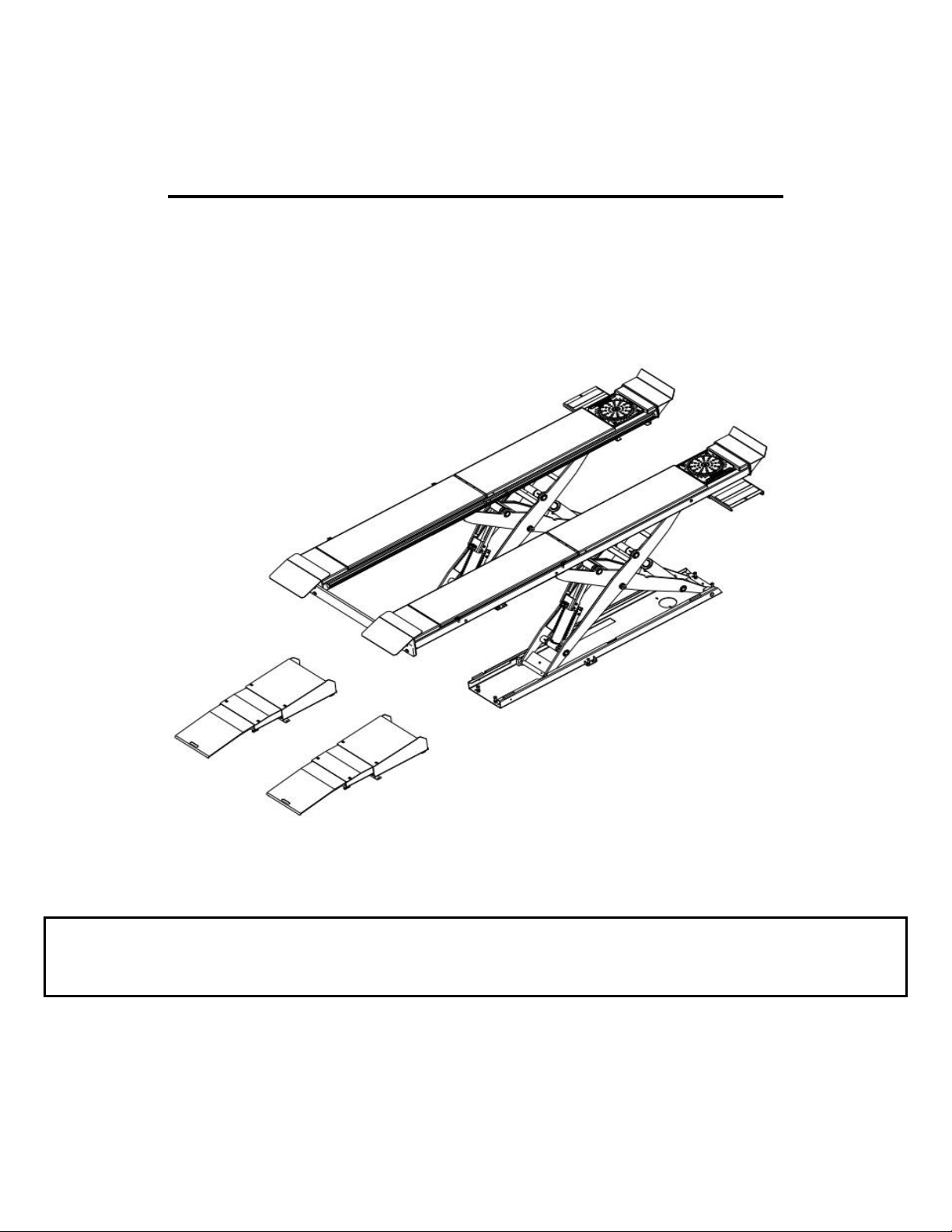
12K SCISSOR LIFT
EELR501A, EELR525A
EELR709A, EELR724A
Nov. 2019 REV.F
309 EXCHANGE AVENUE, CONWAY, ARKANSAS, 72032
TEL: 501-450-1500 FAX: 501-450-1585
EAZ0080V44A

2 of 73
TABLE OF CONTENTS
1.0 IMPORTANT SAFETY INSTRUCTIONS ....................................................... 4
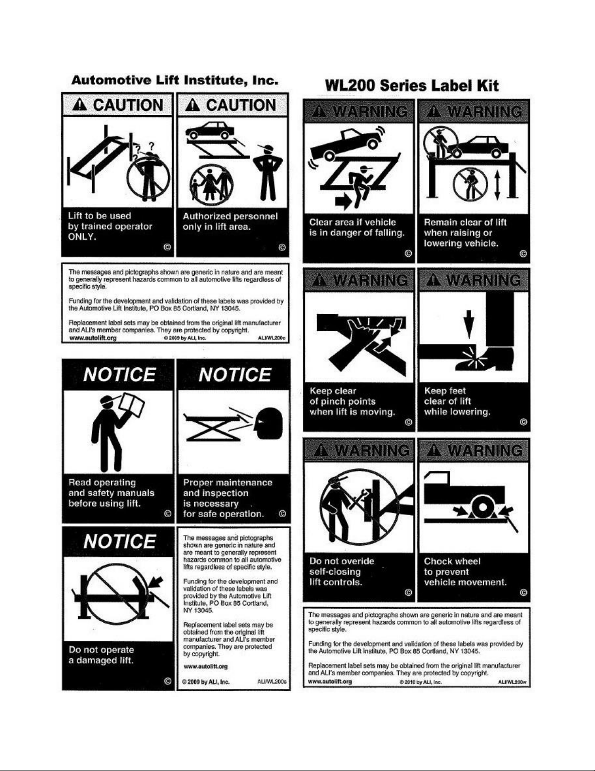
2.0 SAFETY WARNING DECALS ....................................................................... 6
3.0 SPECIFICATIONS ......................................................................................... 7
4.0 CONTENTS .................................................................................................... 9
5.0 TOOLS REQUIRED FOR INSTALLATION OF LIFT ..................................... 9
6.0 INSTALLATION OVERVIEW ....................................................................... 10
7.0
INSTALLATION INSTRUCTIONS ............................................................... 10
7.1
Surface Mount Bay Layout ................................................................ 11
7.2
Baseframe Location ........................................................................... 12
7.3
Flush Mount Bay Layout (Rear Mount Console) .............................. 13
7.4
Flush Mount Bay Layout (Front Mount Console) ............................. 14
7.5
Unpacking the Lift .............................................................................. 15
7.6
Hydraulic Connections ...................................................................... 16
7.7
Air Safety and Auxiliary Air connections.......................................... 19
7.8
Electrical Connections ....................................................................... 22
7.9
Initial Operation .................................................................................. 23
7.10
Bleed The Hydraulic System ........................................................... 24
7.11
Level and Support ............................................................................ 25
7.12
Anchoring Procedure ....................................................................... 26
7.13
Grouting Procedure (Optional) ........................................................ 27
8.0
ACCESSORY INSTALLATION .................................................................... 28
8.1
Installation of Wheel Stops ................................................................ 28
8.2
Installation of Rear Bolster Bar ......................................................... 29
8.3
Installation of Transition Ramps ....................................................... 29
8.4
Position of Approaching ramps ........................................................ 30
8.5
Position of Jack Beams ..................................................................... 32
8.6
Installation of Line Covers ................................................................. 34
8.7
Installation of Extension Line Covers ............................................... 35
9.0
INSTALL FRONT TURNTABLES ................................................................ 36
9.1
Installation of Front Turntables ......................................................... 36
9.2
Moving and Locking the Rear Slip Plate........................................... 36
10.0
FINAL PROCEDURES ............................................................................... 38
10.1
Check of Assembled Lift .................................................................. 38
10.2
Operation Test with Vehicle ............................................................. 38
11.0
LIFT OPERATION ...................................................................................... 39
11.1
Raising the Lift .................................................................................. 39
11.2
Lowering the Lift ............................................................................... 39
11.3
Approaching Ramp Operation ......................................................... 40
12.0
RECOMMENDED INSPECTION AND MAINTENANCE ............................ 42

3 of 73
12.1
Lubrication SPECS ........................................................................... 42
12.2
Mechanical Safety Locks ................................................................. 43
12.3
Air Cylinders, Air Lines, Valve and Fittings .................................... 44
12.4
Hydraulic Power Pack and Hose ..................................................... 44
12.5
Hydraulic Cylinders .......................................................................... 45
12.6
Check Base Frames and Approach Ramps .................................... 45
12.7
Fasteners ........................................................................................... 45
12.8
Transition Ramps, Chocks, Front Wheel Stops ............................. 45
12.9
Runways ............................................................................................ 46
12.10
Front and Rear Steer Plates ........................................................... 46
12.11
Rolling Air Jacks ............................................................................. 46
12.12
Entire Lift ......................................................................................... 46
12.13
Lubrication of Pivot Point and Sliders .......................................... 47
12.14
Lock Out and Tag Out Instructions ............................................... 50
12.15
Emergency Operation .................................................................... 52
13.0 TROUBLE SHOOTING .............................................................................. 54
14.0 RECORD OF MAINTENANCE / TRAINING .............................................. 55
15.0
LIFT PARTS LIST ...................................................................................... 57
15.1
Lift Parts List ..................................................................................... 58
15.2
Ramp Parts List ................................................................................ 59
16.0
HYDRAULIC AND AIR LINE ASSEMBLY ................................................ 61
16.1
Hydraulic Line Routing Map ............................................................ 61
16.2
Hydraulic Line Routing Parts List ................................................... 62
16.3
Hydraulic Circuit Map ....................................................................... 62
16.4
Hydraulic Circuit Parts List .............................................................. 63
16.5
Air Line Routing Part List ................................................................ 63
16.6
Air Line Routing Map ........................................................................ 64
17.0
CONSOLE ASSEMBLY ............................................................................. 65
17.1
Electrical and Control Panel ............................................................ 65
17.2
Console: Pneumatic & Filtering System ......................................... 67
17.3
Console Box Assembly .................................................................... 68
17.4
Console Labeling .............................................................................. 69
17.5
Power Pack ....................................................................................... 70
18.0
ACCESSORY ............................................................................................. 71
18.1
Line Covers and Nails ...................................................................... 71
18.2
Wedge Anchors ................................................................................ 71
18.3
Turntables ......................................................................................... 71
18.4
Jackbeam and Accessory ................................................................ 71
18.5
Hose Extension Kit for Flush Mount - Front Console .................... 71
18.6
Shim kit .............................................................................................. 72
18.7
14L Tank kit ……………………………………………………………….72
APPENDIX FOUNDATION PLAN…………………………………………………….74

4 of 73
1.0 IMPORTANT SAFETY INSTRUCTIONS
When using this lift, basic safety precautions should always be followed, including the following:
1. Only trained and authorized personnel should operate the lift or rolling jacks. Do not allow
customers or bystanders to operate the lift or be in the shop area while lift is in use.
2. Read all instructions in this manual and on the lift thoroughly before installing, operating,
servicing or maintaining the lift. Thoroughly train all employees in the use and care of lift and
rolling jacks.
3. Inspect the lift DAILY. Do not operate if it malfunctions or problems have been encountered.
4. Ensure no one is standing in front or behind the lift while vehicle is being driven onto, or
backed off the lift.
5. Before driving vehicle on, make sure lift is in the fully down position.
6. Before removing vehicle from the lift, make sure lift is in the fully down position and ensure that
all tools have been removed from the deck surfaces.
7. Always raise the lift off safety locks before lowering.
8. Do not allow rear tires or portion of the vehicle to interfere with approach ramp.
9. Be sure front wheel stops are always installed on the lift.
10. Never allow front wheels to strike the front wheel stops.
11. Always use wheel chocks to keep the vehicle from rolling freely on the runways. Wheel chocks
should be used at front and back of the same wheel.
12. Never attempt to overload the lift. The manufacturer’s rated capacity is shown on the
identification label on side of the deck. Do not override the operating controls or safety
devices.
13. Do not permit employees or customers on lift when it is either being raised or lowered.
14. Never raise a vehicle with passengers inside.
15. Always stand clear of lift when raising or lowering and observe "Pinch Points" warning.
16. CAUTION! Never work under the lift unless mechanical safety locks are engaged.
17. Always use Personal Protective Equipment (PPE) when installing or servicing the lift.
18. Always keep the lift area free of obstruction and debris. Grease and oil spills should always be
cleaned up immediately.
19. Always chock vehicle wheels before raising or lowering the lift.
20. Before lowering check the area for any obstructions including people.
21. To protect against risk of fire, do not operate the lift in the vicinity of open containers of
flammable liquids.
22. Adequate ventilation should be provided when working on internal combustion engines.
23. Never open hydraulic lines under pressure.
24. Do not raise or lower the lift with the vehicle on the Jackbeam.
25. For Jackbeam Safety Instructions, see Jackbeam Installation, Operation Manual.

5 of 73
READ AND SAVE THESE INSTRUCTIONS
Installation shall be performed in accordance with ANSO/ALI ALIS, Safety Requirements for
Installation and Service of Automotive Lifts.
For additional safety instructions regarding lifting, lift types, warning labels, preparing to lift, vehicle
spotting, vehicle lifting, maintaining load stability, emergency procedures, vehicle lowering, lift
limitations, lift maintenance, good shop practices, installation, operator training and owner/employer
responsibilities, please refer to “Lifting It Right” (ALI/SM) and “Safety Tips” (ALI/ST).
For additional instruction on general requirements for lift operation, please refer to “Automotive Lift-
Safety Requirements for Operation, Inspection and Maintenance” (ANSI/ALI ALOIM).
A qualified person should be consulted to address seismic loads and other local or state
requirements.
ATTENTION! This lift is intended for indoor installation only. It is prohibited to
install this product outdoors. Operating environment temperature range should
be 41 – 104 °F (5 – 40 °C). Failure to adhere will result in decertification, loss
of warranty, and possible damage to the equipment.
6 of 73
2.0 SAFETY WARNING DECALS

7 of 73
3.0 SPECIFICATIONS
Maximum Capacity:
12000 lbs
5443 kg
Overall Width:
90 Inches
2288 mm
Overall Length:
242 - 294 Inches
6143 - 7467 mm
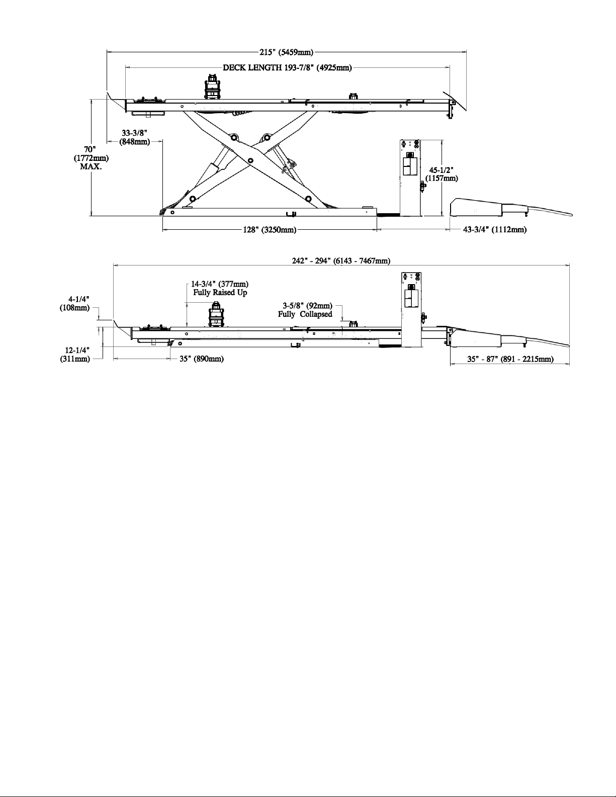
Maximum Raised Height:
70 Inches
1772 mm
Minimum Lowered Height:
12-1/4 Inches
311 mm
Runway Width:
24 Inches
612 mm
Minimum 4 Wheel Alignment W/B:
89 Inches
2260 mm
Maximum 4 Wheel Alignment W/B:
158 Inches
4013 mm
Maximum 2 Wheel Alignment W/B:
165 Inches @Ø30" Tire OD
4190 mm
Maximum General Wheelbase:
179 Inches @Ø30" Tire OD
4546 mm
Raising/Lowering Time (approx.):
95 Seconds / 45 Seconds
Power Ratings:
230V, 1 Ph, 60Hz, 20A
Max. Operation Hydraulic Pressure:
2800 psi
Air Supply requirements:
90 to 140 PSI @5-10CFM
Pneumatic Lubrication Oil Type:
Snap-On #IM6 or Equivalent
Hydraulic Oil Capacity:
Tank size: 4.0 gal
Lift capacity: 6.0 gal
Hydraulic Oil Type:
ISO 32 (10 weight) hydraulic oil
Shipping Weight (Lift Only):
6614 lbs
3000 kg
Jack Beam Fully Raised Up
14-3/4 Inches
377 mm
Jack Beam Fully Collapsed
3-5/8 Inches
92 mm
Extension Adapter for Jack Beam
2-7/16 Inches
62 mm
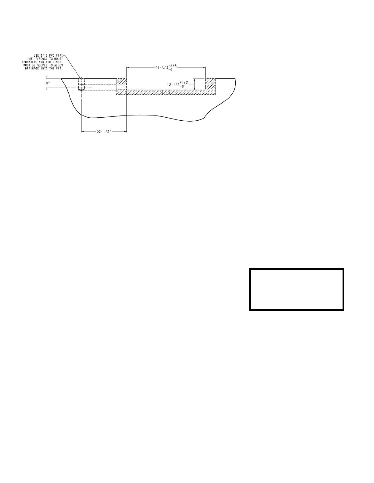
Figure 1 – Lift Dimension (Top View)
Figure 1 – Lift Dimension (Top View)
8 of 73
Figure 2 - Lift Dimensions (Side View)
Figure 3 - Lift Dimensions (Back View)

9 of 73
4.0 CONTENTS
The complete lift is contained in two (2) packages:
1. The main structural components are pre-assembled and packaged on top of each other.
2. The remaining parts are packed in a console/accessory box. Refer to the packing slip inside the
accessory box for a list contents.
Components include:
1pc. – Left Side Assembly
1pc. – Right Side Assembly
2pc. – Jack beams (If ordered)
2pc. – Approaching Ramps
1pc. – Console and Accessory box. (See accessory box list for contents)
1pc. – Grout container
1pc. – Customer care kit including manuals
5.0 TOOLS REQUIRED FOR INSTALLATION OF LIFT
Hammer Drill or similar, 1/4”, 1/2” and 3/4" Concrete Drill Bits
4’ Level
Metric and SAE Wrenches and Sockets
Hammer
Pry Bar – 5’ Long
Chalk Line
Tape Measure
Side Cutters
Screw Drivers
Funnel
Utility Knife
Torque Wrench
Recommended:
Self-leveling laser level
Plumb Bob
Impact Gun
Boom with appropriate capacity, see weight in specification section
Sling and rigging as needed to lift and place structure
Note: Apply LOCTITE #242 on required fasteners where symbol is shown.
If fasteners are removed reapply LOCTITE before re-installing.
10 of 73
6.0 INSTALLATION OVERVIEW
This is the order in which this installation is to take place:
1. Layout the Bay
2. Unpacking the Lift
3. Inspect the Lift
4. Connect Hydraulic Lines
5. Connect Air Lines
6. Connect Electrical
7. Initial Run of Lift
8. Level, Shim and Anchor
9. Install Accessories
10. Install Front Turnplates
11. Final Check
12. Clean
13. Train Customer on Operation of the Lift
IMPORTANT: Shop air must be connected to the inlet port at the FRL unit on the console.
7.0 INSTALLATION INSTRUCTIONS
When the lift arrives on site please read the owner’s installation and operation manual completely.
Check the contents to make sure no parts are missing before starting installation. Gather all of the
tools listed and make sure that the instructions are fully understood before commencing with the
installation.
IMPORTANT: It is the user’s responsibility to provide a satisfactory installation area for
the lift. Lifts should only be installed on a level concrete floor with a minimum thickness
of four and a quarter (4¼) inches or 108 mm. Concrete must have a minimum strength
of 3000 psi or 21 MPa and should be aged thirty (30) days prior to installation. Please
consult the architect, contractor or engineer if doubt exists as to the strength and
feasibility of the floor to enable proper lift installation and operation.
IMPORTANT: It is the user’s responsibility to provide all wiring for electrical hook-up
prior to installation and to ensure that the electrical installation conforms to local
building codes. Where required, it is the user’s responsibility to provide an electrical
isolation switch located in close proximity to the lift that will enable emergency stop
capability and isolate electrical power from the lift for any servicing requirements.
A qualified person should be consulted to address seismic loads and other local or state
requirements.

11 of 73
7.1 Surface Mount Bay Layout
NOTE: Leave any additional room for
any desired aisle or work area.
Recommended clearance around the lift
is a minimum of three (3) feet. Ensure
clearance conforms to local building and
fire codes.
Recommended overhead
clearance is a minimum of twelve (12)
foot ceiling providing 6 feet for the
maximum lift height and 6 feet for the
supported vehicle. For vehicles taller
than 6 feet it is recommended that the
user provides additional overhead
clearance or a shut off mechanism to
stop the lift from raising the vehicle too
high.
Please contact customer service for
latest installation diagram as it may
change without notice.
Note:
Console could
be placed on left
or right of lift.
Figure 4 - Typical Bay Layout

12 of 73
7.2 Base frame Location
Figure 5 – Base frame Locations
IMPORTANT: DO NOT CUT THE SHIPPING
STRAPS HOLDING EACH SCISSOR
ASSEMBLY TOGETHER UNTIL
INSTRUCTED TO DO SO.
1. With reference to Figure 4, the installer
should determine the most suitable
location in the bay for the lift.
2. Snap a chalk line for the centerline of the
lift ensuring that it matches the centerline
of the bay door.
3. Measure and snap two (2) parallel chalk
lines on either side of the centerline for the
inside edges of the base frames. Refer to
Figure 5 for the dimensions necessary to
provide the desired width between the two
runways. A distance of 42-1/4" (1073mm)
between the inside edges of the base
frames will provide the standard width of
40-1/2” (1028mm) between the inside of
the runways, shown on Figure 4.
4. Measure and snap a chalk line parallel to
the shop door for the front of the base
frames, a minimum distance of 262- 3/8"
(6675mm) is recommended.
5. Before proceeding, ensure that once the
runways are installed adequate workspace
will remain in front of the lift. Refer to the
minimum requirements listed in the
installation and operation manual of any
alignment equipment as needed.
Note:
The chalk lines are for reference only.
Refer to the minimum requirements listed in the installation and operation manual
of any alignment equipment as needed.

13 of 73
7.3 Flush Mount Bay Layout (Rear Mount Console)
NOTE: Leave any additional
room for any desired aisle or work
area. Recommended clearance
around the lift is a minimum of
three (3) feet. Ensure clearance
conforms to local building and fire
codes.
Recommended overhead
clearance is a minimum of twelve
(12) foot ceiling providing 6 feet
for the maximum lift height and 6
feet for the supported vehicle.
For vehicles taller than 6 feet it is
recommended that the user
provides additional overhead
clearance or a shut off
mechanism to stop the lift from
raising the vehicle too high.
Please contact customer
service for latest installation
diagram as it may change
without notice.
Figure 6 - Typical Flush Mount
Bay Layout
(Console in Back)
Note:
Console could be placed on
left or right of lift.
14 of 73
7.4 Flush Mount Bay Layout (Front Mount Console)
NOTE: Leave any additional
room for any desired aisle or
work area. Recommended
clearance around the lift is a
minimum of three (3) feet.
Ensure clearance conforms to
local building and fire codes.
Recommended overhead
clearance is a minimum of
twelve (12) foot ceiling
providing 6 feet for the
maximum lift height and 6 feet
for the supported vehicle. For
vehicles taller than 6 feet it is
recommended that the user
provides additional overhead
clearance or a shut off
mechanism to stop the lift
from raising the vehicle too
high.
Please contact customer
service for latest
installation diagram as it
may change without notice.
Figure 7 - Typical Flush
Mount Bay Layout
(Console in Front)
Note:
Console could be placed
on left or right of lift.
Hose Extension Kit
EAK0299T19A
must be ordered for
this routing option.

15 of 73
7.5 Unpacking the Lift
1. Unpack the console and place it in the desired location at the rear of the lift, see Figure 1 and
Figure 4. The console can be placed on either the left or right hand side of the lift.
2. Unpack the runways and lay each base frame along the chalk lines. See Figure 8.
Do not remove the individual strapping on the runways until they have been positioned
on the chalk lines.
3. Position the inside edge of the base frames along chalk lines, and ensure that the runways
are parallel. Ensure that both the inside dimensions (front and back) of the runways as well
the diagonal distances are equal. Refer to Figure 4 for runways dimension, Chalk lines are
for reference only. If minor adjustments are needed to make the runways parallel, this should
be performed.
4. Remove the remaining packing straps, and remove the hydraulic hoses, polytubes air hoses from
under the deck. Hoses are located under the rear portion of the runway and are factory pre-
installed.
5. Inspect lift for damage or any irregularities. If any are found, please contact customer service
before proceeding.
Note: Do not pull excessively on the hoses as it may strain the connections to the base frame.
Ensure that the turntable pockets are at the front, and that Jack Beam rails for each
runway face each other.
Figure 8 – Locate the Lift
Note:
Chalk lines are for reference only.
Runways must be made parallel by measurement.

16 of 73
7.6 Hydraulic Connections
1.
Install Hydraulic Equalization Circuit
Open the rear access cover of the console. Install the hydraulic equalization circuit on the right
side wall of console by using provided hard wares. See Figure 9.
Figure 9 – Hydraulic Circuit Installation
2.
Connect Hydraulic Hose to Power unit
Find the short hydraulic hose (9-0601)
from accessory box, one elbow end
connect to the straight fitting on power
unit, and connect the straight end to the
top elbow of the hydraulic equalization
circuit. See Figure 10.
Figure 10 – Hydraulic Hose Installation
17 of 73
3.
Connect Hydraulic Hoses From Console to Lift
The hydraulic equalization circuit orientation and ports layout refers to Figure 11.
The primary supply lines and equalizing lines from each runway are:
Left Side (L): Right Side (R):
CL CR
EQL EQR
(“C” for “Cylinder” and “EQ” for “Equalize”)
Figure 11 Hydraulic Equalization Circuit
- Unravel all hydraulic hoses and air lines from each runway, and connect each hydraulic lines as
shown in Figure 11 and Figure 12.
- Check the return lines are located beside the base frame slider and tied with other
hydraulic hose, reference to Section 16.1 item #9 in Figure 50.
•
Always make sure that the connections are clean to avoid contaminating the
hydraulic system.
•
Do not kink hydraulic hoses or air lines.
•
Do not remove hydraulic fittings while under pressure
For a flush mount installation with a front mount console requiring a hose extension,
refer to installation instructions 6-4189 provided with kit EAK0299T19A

18 of 73
Figure 12 - Hydraulic Connections

19 of 73
7.7 Air Safety and Auxiliary Air connections
WEAR SAFETY GOGGLES AND PRACTICE CAUTION WHILE
WORKINGWITH COMPRESSED AIR.
1.
Install FRL and Swivel Tee
Find the FRL (Filter/Regulator/Lubricator) assembly
with elbow and Swivel Tee poly from accessory box,
see Figure 13 a).
- Mount FRL assembly on the right side of the console
by using provided hard wares, see Figure 13 b).
Note: do not tighten the nuts at this time.
- Install the Swivel Tee from inside of console through
the big hole on console box to the elbow on the FRL,
see Figure 13 c)
a)
c)
b)
Figure 13 – FRL and Swivel Tee Installation
2.
Install Air Control Valve and Air Lines
Find the air fittings such as Swivel elbow (9-0619), Adapter (9-0620), Reducer (9-0617),
Union Y (9-0618), Ø6mm air hose (9-0622) and Ø6mm air hose (EAH0069V14A) from
accessory box.
- Open the top cover of the console, install the swivel elbow and the adapter onto the air valve
that mounted on console panel as show on Figure 14.
- Insert the reducer into the Swivel Tee, route air hoses and connect to the air fittings on air
control valve, reducer and union Y as show on Figure 14.

20 of 73
Figure 14 – Air Control Valve and Air lines
3.
Connect Air Hoses and Run Testing
- Uncoil the polytubes under each runway that is connected to the safety lock release air cylinder
shown on Figure 15. Route these two lines from base frames to the union ‘Y’ connector in the
console. See Figure 14.
- Uncoil the polytube that one end is connected to the Terminal bolt for Jackbeam on the driver
side runway, shown on Figure 15. Connect other end to the Swivel Tee in the console, See
Figure 14.
IMPORTANT: Use one 1/4" NPT cap to plug terminal bolt before connect to air supply.
- Mount a 1/4” NPT fitting (not supplied) to the inlet port at FRL unit. Connect the shop air supply
line to this fitting. IMPORTANT: Shop air must be connected to the inlet port at the FRL unit
on the console, in order for lift to operate.
- Remove the black hex socket cap on the top of Lubricator, Fill the Lubricator Reservoir with
Snap-On Air Motor Oil #IM6 or Equivalent up to 4/5 of oil reservoir height, re-install the cap.
How to fill oil and adjustment reference to Section 12.3.
- After connecting the main air line, check the air system for any leaks.
Note: The console is equipped with an air Filter/Regulator/Lubricator to ensure a clean air
supply is provided to the safety release cylinders, Jackbeams, The Air Regulator should
be set between 0.62 - 0.83Mpa (90-120psi).
This manual suits for next models
3
Table of contents
Other Snap-on Equipment Scissor Lift manuals

Popular Scissor Lift manuals by other brands


Skyjack
Skyjack SJ6826 RT Operation manual

DINGLI
DINGLI JCPT0607DCS Operator's manual

JLG
JLG 2032E2 Operator's and safety manual

Total Automotive Lifting Solutions Inc.
Total Automotive Lifting Solutions Inc. TLSS14ALOFRR1 Installation, operation & service parts manual

Bend-Pak
Bend-Pak MDS-6 Series Installation and operation manual

Bend-Pak
Bend-Pak SP-7XL Service manual


