SnapAV episode Mini-5.1 User manual

INSTALLATION MANUAL
Mini-5.1 AVR

page | 2
REGULATORY COMPLIANCE AND SAFETY INFORMATION
ElectricalSafety Advisory
Sécurité électrique consultatif
Important Safety Instructions
Consignes de sécurité importantes
Read the safety instructions before using this product.
Lisez lesconsignes de sécuritéavant d’utiliserce produit.
1. Read these instructions.
Lisezces instructions.
2. Keep these instructions.
Conservezces instructions.
3. Heed all warnings.
Respecteztous les avertissements.
4. Follow all instructions.
Suivez toutes les instructions.
5. Do not use this apparatus near water.
Ne pas utilisercet appareilprès de l’eau.
6. Clean only with dry cloth.
Nettoyez-le uniquementavec un chiffon sec.
7. Do not block any ventilation openings. Install in accordance with the
manufacturer’s instructions.
Ne pas bloquer lesouvertures de ventilation.Installer conformément
auxinstructions du fabricant.
8. Do not install near any heat sources such as radiators, heat registers, stoves,
or other apparatus (including amplifiers) that produce heat.
Ne pas installer prèsde sources de chaleurtelles que des radiateurs,
registres de chaleur, poêles, ou autres appareils (incluantles amplificateurs)
quiproduisent de la chaleur.
9. Do not defeat the safety purpose of the polarized or grounding-type plug. A
polarized plug has two blades with one wider than the other. A grounding
type plug has two blades and a third grounding prong. The wide blade or the
third prong is provided for your safety. If the provided plug does not fit into
your outlet, consult an electrician for replacement of the obsolete outlet.
Ne pascontourner le dispositif desécurité de la fichepolarisée ou demise à la
terre. Une fiche polariséepossède deuxlames dontune plus large quel’autre.
Unefiche de terre adeux lames et unetroisième broche de terre. La lame
large oula troisième broche estfournie pour votre sécurité. Sila fiche fournie
nes’adapte pas à votreprise, consultez unélectricien pour le remplacementde
la prise obsolète.

page | 3
© 2021 Wirepath Home Systems, LLC
10.Protect the power cord from being walked on or pinched particularly at plugs,
convenience receptacles, and the point where they exit from the apparatus.
Protégez le cordond’alimentation ne soitpiétiné oupincé, en particulierau
niveau des fiches, des prises et au pointoù il sort del’appareil.
11.Only use attachments/accessories specified by the manufacturer.
Utilisez uniquement des fixations/ accessoires spécifiéspar le fabricant.
12.Use only with the cart, stand, tripod, bracket, or table specified by the
manufacturer, or sold with the apparatus. When a cart is used, use caution
when moving the cart/apparatus combination to avoid injury from tip-over.
Utilisez uniquement avec lechariot, le socle, le trépied, le support ou la table
spécifiés parle fabricant ouvendu avec l’appareil. Lorsquevous utilisez un
chariot, soyez prudent lorsque vousdéplacez l’ensemble chariot/ appareil
pour éviterdes blessuresdues au renversement.
13.Unplug this apparatus during lightning storms or when unused for long
periods of time.
Débranchez cetappareil pendant les oragesoulorsqu’il n’est pas
utilisépendant de longues périodesde temps.
14.Refer all servicing to qualified service personnel. Servicing is required when
the apparatus has been damaged in any way, such as power-supply cord
or plug is damaged, liquid has been spilled or objects have fallen into the
apparatus, the apparatus has been exposed to rain or moisture, does not
operate normally, or has been dropped.
Confiez toutes les réparationsà un personnel qualifié. Une réparation est
nécessairelorsque l’appareil aété endommagé de quelquefaçon que ce soitle
cordon d’alimentationou la fiche estendommagé, du liquidea été renversé
ousi des objets sonttombés dans l’appareil, l’appareil a étéexposé à la pluieou
à l’humidité, ne fonctionne pas normalement, ou s’il est tombé.

page | 4
15.This equipment uses AC power which can be subjected to electrical surges,
typically lightning transients which are very destructive to customer terminal
equipment connected to AC power sources. The warranty for this equipment
does not cover damage caused by electrical surge or lightning transients. To
reduce the risk of this equipment becoming damaged it is suggested that the
customer consider installing a surge arrestor.
Cet équipement utilisela puissanceACqui peuvent êtresoumis à
dessurtensions électriques, la foudregénéralementtransitoiresqui
sonttrès destructives envers leséquipements terminauxconnectés à
des sourcesd’alimentation CA. Lagarantie de cet appareilne couvre pas
lesdommages causés par lessurtensionsélectriques outransitoires de foudre.
Pour réduire le risquede cet équipementdevientendommagé, ilest suggéré
quele clientenvisager l’installation d’un limiteur de surtension.
16.To completely disconnect unit power from the AC mains, remove the power
cord from the appliance coupler and/or turn off the circuit breaker. To
reconnect power, turn on the circuit breaker following all safety instructions
and guidelines.The circuit breaker shall remain readily accessible.
Pour débrancher complètement l’alimentation secteur du réseau secteur,
retirez le cordon d’alimentation du coupleur de l’appareil et / ou éteignez
le disjoncteur. Pour reconnecter l’alimentation, allumez le disjoncteur en
suivant toutes les consignes et consignes de sécurité. Le disjoncteur doit être
facilement accessible.
17.This product relies on the buildings installation for short-circuit (overcurrent)
protection. Ensure that the protective device is rated not greater than: 20A.
Ce produit repose sur l’installation des bâtiments pour les courts-circuits
(surintensité) de protection. Assurez-vous que le dispositif de protection est
assignée ne dépassant pas: 20A.
18.Never push objects of any kind into this product through cabinet slots as they
may touch dangerous voltage points or short out parts that could result in fire
or electric shock.
N’introduisez jamais d’objetsd’aucune sorte dansce produità travers les
fentesdu boîtier car ilspourraient toucher des pointsde tension dangereux
oucourt-circuiter despiècesqui pourraiententraîner un incendie ouun choc
électrique.
19.This product can interfere with electrical equipment such as tape recorders,
TV sets, radios, computers and microwave ovens if placed in close proximity.
Ce produit peut interféreravec des appareils électriquestels que les
magnétophones, téléviseurs, radios, ordinateurs etfoursà micro-
ondessiplacésà proximité.

page | 5
© 2021 Wirepath Home Systems, LLC
The lightning flash and arrow head within the triangle is a
warning sign alerting you of dangerous voltage inside the
product
L’éclair etla flèche dans letriangle estun signe d’alertepour
vous avertird’une tension dangereuseà l’intérieur duproduit
Caution: To reduce the risk of electric shock, do not remove
cover (or back). No user serviceable parts inside. Refer
servicing to qualified service personnel.
Attention: Pour réduirele risque de chocélectrique, nepas
retirer le couvercle(ou l’arrière). Aucune pièceréparable par
l’utilisateur. Confiez l’entretienà un personnel qualifié.
The exclamation point within the triangle is a warning sign
alerting you of important instructions accompanying the
product.
Le point d’exclamationdans un triangle
estun signed’avertissement voussignale des
instructionsimportantes accompagnant le produit.
AC voltage: This symbol indicates that the rated voltage marked with the symbol
is AC voltage.
CAUTION: FOR CONTINUED PROTECTION AGAINST THE RISK OF FIRE REPLACE
ONLY WITH SAME TYPE OF FUSE.
Save these instructions
Conservezces instructions
Compliance of this equipment is confirmed by the following label that is placed
on the equipment:
Conformité de cet appareilest confirmépar le symbole suivantqui est placésur
l’équipement:

page | 6
USA Compliance
FCC Part 15, Subpart B & IC Unintentional Emissions Interference
Statement
This equipment has been tested and found to comply with the limits for a Class B
digital device, pursuant to Part 15 of the FCC rules. These limits are designed to
provide reasonable protection against harmful interference when the equipment
is operated in a residential installation. This equipment generates uses and
can radiate radio frequency energy and, if not installed and used in accordance
with the instructions, may cause harmful interference to radio communications.
However, there is no guarantee that interference will not occur in a particular
installation. If this equipment does cause harmful interference to radio or
television reception, which can be determined by turning the equipment off and
on, the user is encouraged to try to correct the interference by one or more of the
following measures:
•
Reorient or relocate the receiving antenna.
•
Increase the separation between the equipment and receiver.
•
Connect the equipment into an outlet on a circuit different from that to which
the receiver is connected.
•
Consult the dealer or an experienced radio/TV technician for help.
This device complies with part 15 of the FCC rules. Operation is subject to the
following two conditions: (1) This device may not cause harmful interference, and
(2) this device must accept any interference received, including interference that
may cause undesired operation.
Cet appareil est conforme à la section 15 des règles. Son utilisation est soumise
aux deux conditions suivantes: (1) Cet appareil ne doit pas causer d’interférences
nuisibles et (2) cet appareil doit accepter toutes les interférences reçues, y
compris celles pouvant entraîner un fonctionnement non souhaité.
MPE Requirements:
To satisfy FCC / IC RF exposure requirements, a separation distance of
20 cm or more should be maintained between the antenna of this device
and persons during device operation.To ensure compliance, operations at
closer than this distance is not recommended.
Les antennes installées doivent être situées de facon à ce que la
population ne puisse y être exposée à une distance de moin de 20 cm.
Installer les antennes de facon à ce que le personnel ne puisse
approcher à 20 cm ou moins de la position centrale de l’ antenne.
La FCC des éltats-unis stipule que cet appareil doit être en tout temps
éloigné d’au moins 20 cm des personnes pendant son functionnement.
Canada Warning Statement
CAN ICES-3 (B)/NMB-3(B)
•
This product meets the applicable Innovation, Science and Economic
Development Canada technical specifications.
•
Ce produit répond aux spécifications techniques applicables à l’innovation,
Science et Développement économique Canada.

page | 7
© 2021 Wirepath Home Systems, LLC
Europe Compliance
Compliance of this equipment is confirmed by the following logo that is placed on
the product ID label that is placed on the bottom of the equipment. The full text
of the EU Declaration of Conformity (DoC) is available on the regulatory webpage:
Australia & New Zealand Compliance
Compliance of this equipment is confirmed by the following logo that is placed on
the product ID label that is placed on the bottom of the equipment.
Recycling
Wirepath Home Systems, LLC understands that a commitment to the
environment is essential for a health life and sustainable growth for future
generations. We are committed to supporting the environmental standards,
laws, and directives that have been put in place by various communities and
countries that deal with concerns for the environment. This commitment is
represented by combining technological innovation with sound environmental
business decisions.
WEEE Compliance
Wirepath Home Systems, LLC is committed to meeting all requirements of the
Waste Electrical and Electronic Equipment (WEEE) directive (2012/19/EC). The
WEEE directive requires the manufacturers of electrical and electronic equipment
who sell in EU countries: (1) label their equipment to notify customers that it
needs to be recycled, and (2) provide a way for their products to be appropriately
disposed of or recycled at the end of their product lifespan. For collection or
recycling of Wirepath Home Systems, LLC products, please contact your local
Wirepath Home Systems, LLC representative or dealer.

page | 8
FRONT AND REAR PANEL DESCRIPTIONS
Front panel
A. Power LED light bar: Blue is at its highest intensity on the left side of the
light bar.
• Blue LED on = Amplifier is active or in standby mode.
• Blue LED off = Amplifier power is off.
B. SUB (LFE) channel LED: Displays the status for sub out.
• Blue LED: LFE signal has been decoded (is present), and audio is being
sent to the subwoofer line out.
• LED off: LFE signal is not present.
C. Speaker channel LEDs: Indicate the amplifier’s operating state. Each
channel has one bi-color LED.
• Blue LED: Amplifier is on and functioning properly.
• Red LED: Amplifier is on and is
not
functioning properly. Check for
possible short at speaker output.
• LED off (when power LED is blue): Amplifier channel is off.
D. Input LED: Blue LED displays the active input source.
• Blue LED: The input source is active.
• LED off: The input source is inactive.
E. Decoding LED: Displays the status for Dolby/DTS decoding.
• Blue LED: Dolby/DTS input signal is decoding.
• LED off: No Dolby/DTS signal is being received via input.
F. Power button:
• Press and release (momentary) to turn on or put it into Standby mode.
• Press and hold for 10 seconds to put it into deep Standby mode (<0.5W).
A B C D E F

page | 9
© 2021 Wirepath Home Systems, LLC
Back panel
A. Bluetooth Antenna
B. Speaker outputs: 10-position Phoenix-style connectors for 5-channel
speaker wiring.
C. LFE OUTPUT (subwoofer output): Unbalanced port to connect an external
subwoofer.
D. RESET: A pinhole button for resetting the amplifier.
• Quick momentary press = Reboot.
• Press and hold for 5 seconds = Returns network to DHCP defaults.
• Press and hold for 10+ seconds = Returns device to its factory default
configuration.
E. AUX/OPTICAL input: 3.5 mm combo jack.
• 3.5 mm stereo port for connection to the analog line output of your
audio/video source.
• 3.5 mm optical adapter for connecting to the optical audio output of your
TV or other audio/video source.
F. HDMI IN ports (3): HDMI type A connector for connecting to the HDMI output
of your audio/video source.
G. HDMI OUT (ARC) [audio return channel]: HDMI type A connector (1).
• For connection to the HDMI(ARC) input on your TV
H. Network: Standard RJ45 connector with LED indicator. 10/100 Ethernet.
Port remains active when amp is in Standby mode.
I. IR power ON/OFF: If on, +12V DC is applied to the IR IN jack, providing
power for an external IR receiver.
• Note: Do not turn on IR power if a direct connection to a control system
is used.
J. IR Status: LED illuminates when the IR signal is received
K. IR IN: 3.5 mm stereo port. The adaptive IR input circuit supports 38 KHz
carrier frequencies.
L. Power connector: Use the supplied power cord to connect power.
100-120V/220-240V~
50/60Hz 200W
A B C D E F G H I J K L
page | 10
MOUNTING THE AMPLIFIER
Package contents
• EA-MINI-5.1D-200
• IEC power cable (1)
• Optical adapter (1)
• Feet (4)
• Bracing foot, rack-mount ears, and screws
• VersaBox mounting screws (4)
• Phoenix-style speaker connectors
• Bluetooth antenna
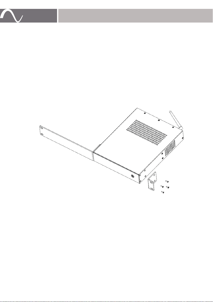
Mounting in a rack
CAUTION! To prevent damage, maintain adequate ventilation space to the sides
of the amplifier. Amplifier can be stacked vertically, but be sure to not place the
amplifier next to other components or against the side of a cabinet. Doing so will
block ventilation openings.

page | 11
© 2021 Wirepath Home Systems, LLC
Mounting in a Strong VersaBox
Using the provided screws, attach the amplifier to the VersaBox plate at the
circled mount points. (14x14” VersaBox shown)
CONNECTING NETWORK AND POWER
This device is designed to operate as part of the home system, which requires
physical audio connections and connections in Composer Pro to function as
designed. This section describes how to set up the physical connections required
for the amplifier and some devices associated with it.
WARNING! Connecting speaker wires or input cables while the amplifier is
powered may cause electrical shock and could damage the amplifier. Unplug the
amplifier and some of the devices associated with it.
To connect the amplifier to NETWORK and power ports:
1. Connect an Ethernet Cat 5e/6 cable from a local network connection into the
RJ45 port.
2. Connect the provided power cable to the amplifier’s power input and to a
power outlet.
3. When the power cable is first connected, the amplifier initially turns on in
Standby mode. Press the front-panel power button to fully power up.
FRONT PANEL
REAR PANEL
270 mm (10.63”)
211 mm (8.31”)

page | 12
CONNECTING TO TV
HDMI (recommended)
1. Connect an HDMI cable from the HDMI OUT (ARC) output on the back of the
amplifier to the HDMI IN (ARC) input on your TV.
Notes:
• An HDMI connection supports digital audio and video with a single connector.
It is the best option for connecting your amplifier.
• If your TV features an HDMI ARC connector, you can enjoy the TV audio
through your amplifier by using a single HDMI cable.
• An HDMI connection is required if you intend to connect additional source
devices to the amplifier’s AVR inputs to display them on your TV.
• If you want to enable HDMI CEC, you must do so on both your TV (using
the TV’s user interface) and on the Mini-5.1 AVR (using the browser user
interface). HDMI CEC (consumer electronics control) is a feature that allows
compatible devices to be controlled from a single remote control. For details,
refer to your TV’s instruction manual.
Optical digital input
1. Connect the OPTICAL IN connector of the amplifier to the OPTICAL OUT
connector of your TV with an optical cable.
2. Enable Use Optical through the browser user interface.
Notes:
• Make sure the protective cap has been removed from both ends of the optical
cable.
• Make sure you have connected one optical adapter
before
inserting into the
amplifier.
CONNECTING TO OTHER DEVICES
HDMI (recommended)
To connect other audio/video sources such as a satellite receiver, DVD player,
and game console, we recommend you connect them using HDMI to one of the 3
HDMI inputs of the amplifier.
1. Connect one of the 3 HDMI IN on the back of the amplifier to the HDMI OUT
output on your audio/video source using an HDMI cable.
Note:
• We strongly recommend you connect other audio/video sources directly
to the amplifier, and not directly to the TV. This is the best way to ensure
the best possible multichannel audio format / audio signal is reproduced
accurately for each source.

page | 13
© 2021 Wirepath Home Systems, LLC
Optical digital input
1. Connect the OPTICAL IN connector of the amplifier to the OPTICAL OUT
connector of your audio/video source with an optical cable.
2. Enable Use Optical through the browser user interface.
Notes:
• Make sure the protective cap has been removed from both ends of the optical
cable.
• Make sure you have connected one optical adapter
before
inserting into the
amplifier.
Connecting with Bluetooth
You can conveniently connect the amplifier to your mobile device wirelessly with
Bluetooth.
To establish a Bluetooth® connection:
1. Make sure the included Bluetooth antenna is installed on the back of the
amplifier.
2. Enable the input (Bluetooth) through the browser user interface.
3. Start the search on your mobile device.
4. Select EA-MINI-5.1D-200 as the playback device. After confirmation, the
connection is established automatically.
5. Start a title on your mobile device, and the sound should automatically output
through the amplifier.
Connecting with AUX
1. Connect a 3.5 mm stereo cable from the AUX port on the back of the amplifier
and the line out on your mobile device. Or, connect a 3.5 mm-to-RCA stereo
cable to the unbalanced output port of any audio/video source.
2. Disable Use Optical through the browser user interface.
page | 14
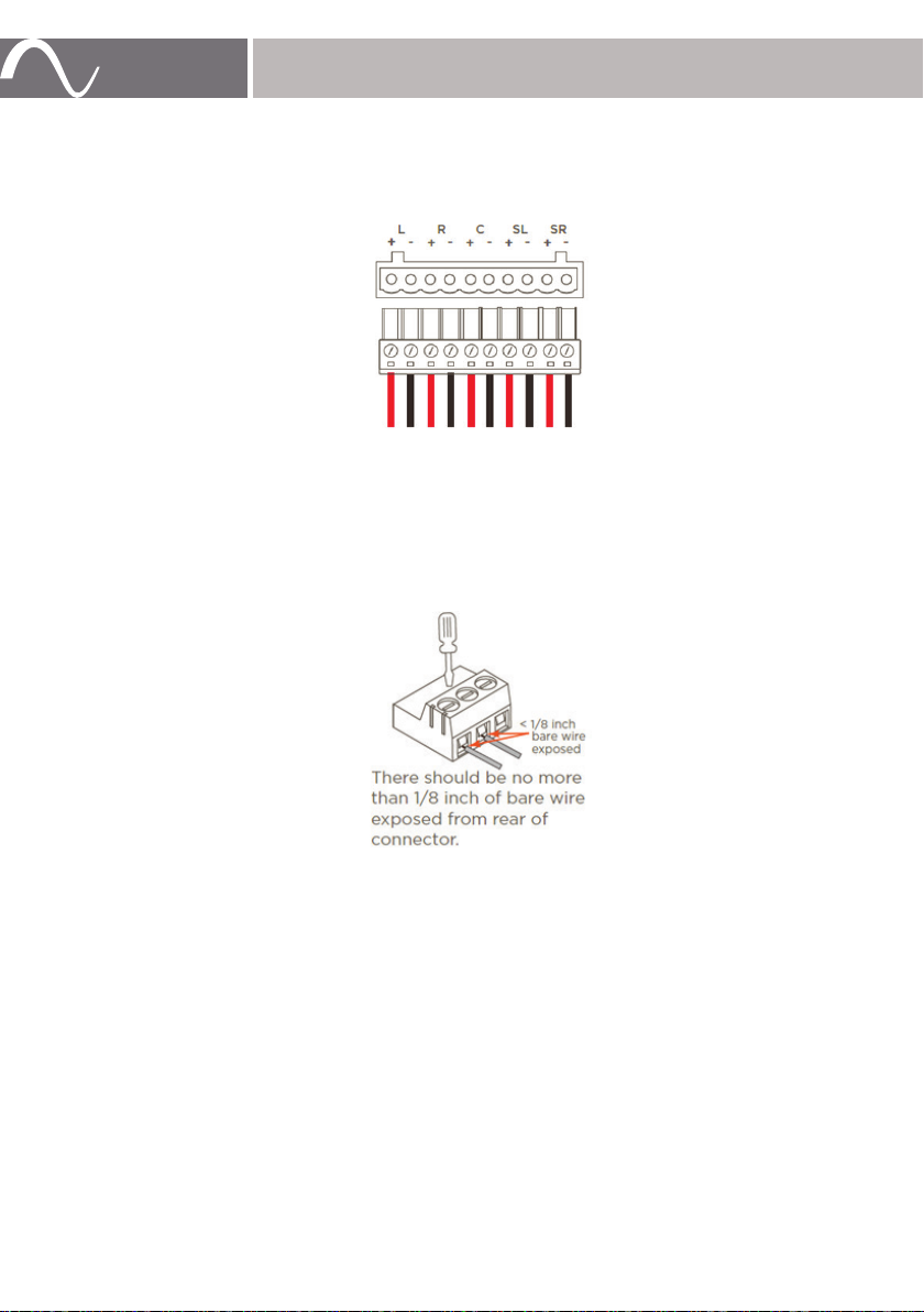
CONNECTING SPEAKERS
A ten-position screw-down plug-in connector is supplied for making connections
to any of the five supported speakers. The diagram below shows how to make
connections.
Caution: Observe correct polarity when making speaker connections.
When connecting wires to the 10-position screw-down connector, follow the
guidelines below to ensure a safe and secure connection.
1. With a small slotted screwdriver, turn the screws on the connector
counterclockwise until the silver crimp opens enough to slide wire(s) into the
square slots.
2. Strip insulation from the wire so about 3 mm (1/8 inch) of bare wire is
exposed.
3. Insert the stripped wire into the proper connection, and turn screws clockwise
until the crimps tighten around each wire. Lightly tug on each wire to ensure
a secure connection.
Tips:
• #16 AWG is recommended for lengths up to 15 meters (about 50 feet).
• #14 AWG is recommended if wire length is longer than 15 meters (about 50
feet) but less than 30 meters (about 100 feet).
• #12 AWG is recommended if wire length is longer than 30 meters (about 100
feet) but less than 90 meters (about 300 feet).

page | 15
© 2021 Wirepath Home Systems, LLC
LFE output
The LFE (low-frequency effects) port accepts a standard RCA cable and connects
to the LFE input on a subwoofer speaker.
USING THE BROWSER INTERFACE
1. Connect an Ethernet Cat 5e/6 cable from a local network connection into the
RJ45 port on the amplifier.
2. Power on the amplifier.
3. In a web browser on the same local network, enter the amplifier’s IP address
that was assigned by the router (such as 192.168.1.2). The login screen
opens.
4. Enter the default user name (“episode”) and the default (first-time only)
password “episode”. The amplifier’s configuration screen opens.
Note: The first time you access the interface, or after a reset to factory
default settings, you must change the password.

page | 16
Basic operation
1. Set the volume gain for different input through level trim bar.
2. Select the sound mode for current input:
Note: Sound mode selection applies only to audio content that is not
Dolby/DTS. If the amplifier receives a Dolby/DTS signal, it will decode and
output Dolby/DTS.
• 2ch Stereo: Stereo only via front left/right and subwoofer
• 5ch Stereo: Stereo via all channels (upmix)
• Dolby PLII Music: Dolby ProLogic II for music
• Dolby PLII Movie: Dolby ProLogic II for movies

page | 17
© 2021 Wirepath Home Systems, LLC
Main functions
1. Adjust the Speaker Setup parameters for each channel, including speaker
size, crossover, slope, speaker level, and test tone.
• Speaker size: You can set the size of the speakers according to your
speaker system. Large and Small are the two options for the Front Left,
Center, Front Right, Surround Left, and Surround Right speakers. On and
Off are the two options for the Subwoofer output.
• Crossover: With the crossover frequency, you define the frequency up to
which the subwoofer should be active.
• Slope: With the slope setting, you can set the frequency rolloff
(steepness) of the crossover filters. Options include 6, 12, and 24 dB per
octave. Lower values result in a more gradual rolloff, and higher values
result in a more agressive rolloff.
• Speaker Level: Set the relative volume within a range from –10
(decrease) to +10 (increase) for each speaker.
• Distance: Speakers are usually located at different distances from the
listening position, which may compromise the surround sound effect.
Here, you can set a slight delay of the signal to compensate these
differences for all channels. Measure the distance from the listening
position to the speakers and enter these values in the menu. The system
calculates the required delays to each channel.
• Test signal: You can activate and deactivate pink noise as a neutral test
sound.

page | 18
Configuring the default power on settings
• Power On Input: Determines which input is selected automatically when
the amplifier is turned on.
• Power On Sound Mode: Determines which sound mode is selected when
the amplifier is turned on.
• Note: Sound mode selection applies only to audio content that is not
Dolby/DTS. If the amplifier receives a Dolby/DTS signal it, will decode
and output Dolby/DTS.
• Power On Volume: Determines the volume level of the amplifier when it
is turned on.
Configuring the CEC settings
• CEC can be enabled or disabled on the amplifier for Power On, Power Off,
Source selection, and Volume control.
• HDMI CEC (consumer electronics control) is a feature that allows
compatible devices to be controlled from a single remote control. For
details, refer to your TV’s instruction manual.
Configuring Standby mode and HDMI pass-through
Network Standby on: Enables the standby feature for the amplifier.
• RJ45 port is connected: The amplifier will go to networked Standby
mode without any signal input for 15 minutes.
• RJ45 port is disconnected: The amplifier will go to Standby mode
without any signal input for 15 minutes.
Network Standby off: disables Standby for the amplifier.
HDMI Audio Out: Determines whether the audio signals from the
connections HDMI1, HDMI 2, and HDMI3 are also looped through to the TV
set.

page | 19
© 2021 Wirepath Home Systems, LLC
SPECIFICATIONS
General
Power requirements 100-120V/220-240V~50/60 Hz
Power consumption <0.4W (Standby mode)
1.3W (networked Standby mode)
Max 300W (Mini 5.1 AVR)
Dimensions (L x D x W)
(without feet)
270 × 211 × 44.5 mm
(10.63 × 8.31 × 1.75 in.)
Weight Without packaging: 2.25 kg (5.0 lb)
With packaging: 3.6 kg (7.9 lb)
Audio
Power output @4 ohm 3 x 50W (FL, C, FR)
2 x 25W (SL,SR)
Frequency 20 Hz to 20 KHz, ±1 dB at
1/8 power @4 ohm
Signal-to-noise ratio >90 dB A-weighted @rated power
THD+N <0.2% 1 KHz @rated power 4 ohm
Minimum impedance 4 ohm
Input impedance 20 kΩ @AUX input
Bluetooth
Frequency range 2402 MHz~2480 MHz
Transmitter power 0-7 dBm
Modulation GFSK, π/4-DQPSK, 8-DPSK
Profile BT 3.0, A2DP v1.2, AVRCPv1.4
HDMI
HDMI HDMI 2.0 (with audio return channel,
3D 4K, HDR @4K30, deep color)
HDCP HDCP 2.2

© 2021 Wirepath Home Systems LLC
200-EA-MINI-5.1D-200-A 20210126-MS
CONTACTING TECHNICAL SUPPORT
866.838.5052
LEGAL NOTICES
Warranty and legal information
Find details of this product’s 2-Year Limited Warranty at snapav.com/
warranty, or request a paper copy from Customer Service at (866)
424-4489. Find other legal resources, such as regulatory notices, patent
information, and safety information, at snapav.com/legal.
Trademark information
Manufactured under license from Dolby Laboratories. Dolby, Dolby Audio,
and the double-D symbol are trademarks of Dolby Laboratories Licensing
Corporation.
For DTS patents, see http://patents.dts.com. Manufactured under license
from DTS, Inc. (for companies headquartered in the U.S./Japan/Taiwan) or
under license from DTS Licensing Limited (for all other companies). DTS,
Digital Surround, and theDTS logo are registered trademarks or trademarks
of DTS, Inc. in the United States and other countries. © 2020 DTS, Inc. ALL
RIGHTS RESERVED.
The Bluetooth® word mark and logos are registered trademarks owned by
Bluetooth SIG, Inc. and any use of such marks by SNAP AV is under license.
Other trademarks and trade names are those of their respective owners.
This manual suits for next models
1
Table of contents


