SnapNrack S100 User manual

| SnapNrackTM
SERIES 100
Roof MounT InSTallaTIon Manual
| i
SERIES 100 ROOF MOUNT
CODE COMPLIANT
INSTALLATION
MANUAL |2012

Table of Contents
1. INTRODUCTION....................................................................................................................................................3
1.1 OVERVIEW OF THE SNAPNRACK SYSTEM..........................................................................................3
1.2 OVERVIEW OF THIS MANUAL................................................................................................................4
1.3 YOUR RESPONSIBILITY AS INSTALLER ................................................................................................4
1.4 SUPPORT.......................................................................................................................................................5
2. PREPARE FOR THE INSTALLATION...............................................................................................................6
2.1 IDENTIFY TYPE OF ROOF.........................................................................................................................6
2.2 IDENTIFY SNAPNRACK COMPONENTS...............................................................................................6
2.3 OBTAIN INSTALLER SUPPLIED TOOLS AND MATERIALS ...............................................................9
2.4 SURVEY THE SITE .......................................................................................................................................9
2.5 LAY OUT SYSTEM ON THE ROOF........................................................................................................10
3. FLUSH MOUNT ON COMPOSITION ROOFS (USING L-FEET)...........................................................13
3.1 INTRODUCTION .......................................................................................................................................13
3.2 LOCATE ATTACHMENT POINTS...........................................................................................................14
3.3 DRILL PILOT HOLES.................................................................................................................................14
3.4 SECURE BASE.............................................................................................................................................15
3.5 INSTALL FLASHING..................................................................................................................................15
3.6 ATTACH L-FOOT........................................................................................................................................16
4. FLUSH MOUNT ON OTHER ROOF TYPES (USING STANDOFFS)....................................................17
4.1 INTRODUCTION .......................................................................................................................................17
4.2 DETERMINE TYPE AND SIZE OF ATTACHMENT AND FLASHING..............................................18
4.3 STANDOFF BASE OPTIONS.................................................................................................................. 20
4.4 LOCATE ATTACHMENT POINTS.......................................................................................................... 20
4.5 MARK ATTACHMENT POINTS.............................................................................................................. 20
4.6 DRILL PILOT HOLES................................................................................................................................ 20
4.7 SECURE THE BASE....................................................................................................................................21
4.8 ATTACH STANDOFF AND INSTALL FLASHING............................................................................... 22
5. INSTALL ON OTHER TYPES OF ROOF PENETRATIONS .................................................................... 22
5.1 INSTALLATION WITH HANGER BOLTS.............................................................................................. 22
5.2 DETERMINE LENGTH OF HANGER BOLT......................................................................................... 23
5.3 LOCATE & MARK ATTACHMENT POINTS......................................................................................... 23
5.4 DRILL PILOT HOLES AND INSERT HANGER BOLTS....................................................................... 23
5.5 FASTENING HANGER BOLT CLAMP ...................................................................................................24
5.6 INSTALLATION WITH CORRUGATED ROOF BLOCK ......................................................................24
5.7 LOCATE, MARK & DRILL ATTACHMENT POINTS ........................................................................... 25
5.8 INSTALL CORRUGATED ROOF BLOCK.............................................................................................. 25
5.9 INSTALLATION WITH STANDING SEAM CLAMPS......................................................................... 25
5.10 IDENTIFICATION OF SEAM TYPE........................................................................................................ 26
5.11 DETERMINE CLAMP LAYOUT AND HARDWARE........................................................................... 26
5.12 INSTALL CLAMP AND HARDWARE.................................................................................................... 26

| SnapNrackTM
SERIES 100
Roof MounT InSTallaTIon Manual
6. TILT MOUNT (USING STANDOFFS AND EXTENSIONS) .....................................................................27
6.1 INTRODUCTION .......................................................................................................................................27
6.2 DETERMINE TYPE OF TILT ASSEMBLY...............................................................................................27
6.3 SHALLOW TILT KITS.................................................................................................................................27
6.4 FULL TILT KITS.......................................................................................................................................... 28
6.5 INSTALLING ON L-FEET ......................................................................................................................... 30
7. INSTALL RAILS.................................................................................................................................................... 30
7.1 SNAP IN CHANNEL NUTS ..................................................................................................................... 30
8. INSTALL RAIL SPLICES .................................................................................................................................... 30
8.1 SNAP IN SPLICE INSERT......................................................................................................................... 30
9. LEVEL RAILS .........................................................................................................................................................31
9.1 OVERVIEW...............................................................................................................................................................31
9.2 ADDITIONAL LEVELING FOR L-FOOT MOUNTED RAILS ............................................................31
9.3 ADDITIONAL LEVELING FOR STANDOFF MOUNTED RAILS ......................................................32
10. INSTALL MODULES ON RAILS ......................................................................................................................33
10.1 PREPARE CLAMPING HARDWARE ......................................................................................................33
10.2 SET FIRST MODULE ................................................................................................................................ 34
10.3 CONNECT WIRING.................................................................................................................................. 35
10.4 CONNECT GROUNDS............................................................................................................................. 36
10.5 TRIM RAILS................................................................................................................................................ 36
11. FINAL CHECK....................................................................................................................................................... 36
11.1 CHECK ALL BOLTS................................................................................................................................... 36
11.2 CHECK WIRES AND GROUNDING...................................................................................................... 36
11.3 INSTALL END CAPS..................................................................................................................................37
12. ARRAY EDGE SCREEN.......................................................................................................................................37
12.1 EDGE SCREEN OVERVIEW......................................................................................................................37
12.2 MEASURE ARRAY PERIMETER..............................................................................................................37
12.3 INSTALL ARRAY EDGE SCREEN CLIPS ................................................................................................37
12.4 TRIM AND INSTALL EDGE SCREEN.....................................................................................................37
13. APPENDIX............................................................................................................................................................. 38
13.1 ENGINEERING CERTIFICATION LETTER............................................................................................ 38
13.2 RAIL SPAN TABLES...................................................................................................................................47
13.3 SNAPNRACK WARRANTY ..................................................................................................................... 78

| SnapNrackTM
SERIES 100
Roof MounT InSTallaTIon Manual
| 3
1. Introduction
1.1 Overview of the SnapNrack System
SnapNrack Series 100 PV Mounting System oers a low prole, visually appealing, photovoltaic
(PV) module installation system. This innovative system simplies the process of installing solar
PV modules, shortens installation times, and lowers installation costs.
SnapNrack systems, when installed in accordance with this manual, will be structurally
adequate for the specic installation site and will meet the local building code and the
International Building Code.
The SnapNrack installation system is a set of engineered components that can be assembled
into a wide variety of PV mounting structures. It is designed to be installed by qualied solar
installation technicians. With SnapNrack you will be able to solve virtually any PV module
mounting challenge.
Figure 1.0 - Placing modules on S100 standard rails installed on L-Feet

| SnapNrackTM
SERIES 100
Roof MounT InSTallaTIon Manual
4 |
1.2 Overview of this Manual
This manual describes the installation procedures for standard roof mounting for common
photovoltaic (PV) arrays. It guides you through the correct procedures for mounting the
SnapNrack PV module racking system on the major types of roof structures and materials. It
also provides layout guidelines, installation tips and directions.
Review this entire manual before installing the SnapNrack system.
Throughout this manual you will see highlighted notes which will provide you with dierent
types of information:
4NOTICES indicate important information to help with the installation or to avoid
potential damage to the structure or components.
8 CAUTIONS indicate a potential for property damage, personal injury, or death.
For help with your installation, call SnapNrack technical support. Visit www.snapNrack.com
and click Contact in the top menu bar.
For information on Ground Mount installation procedures, refer to SnapNrack Ground Mount
Installation Manual. It can be downloaded from www.snapNrack.com
1.3 Your responsibility as installer
Comply with all applicable local or national building codes, including any that may supersede
this manual.
• MakesurethattheSnapNrackcomponentsandotherproductsareappropriateforthe
particular installation and the installation environment.
• Makesurethattheroof,itsrafters,connections,andotherstructuralmemberscan
support the array in compliance with all applicable code requirements.
• UseonlySnapNrackpartsandcomponents.
• Makesurethatlagscrewsorroofattachmentfastenersareproperlyandsecurely
attached to the roof rafters or structural members and that roof members are structurally
sound.

| SnapNrackTM
SERIES 100
Roof MounT InSTallaTIon Manual
| 5
• Maintainthewaterproofintegrityoftheroof,includingtheproperuseofroong
sealant and selection of appropriate ashings for post type installations (see section 4
for ush-mount installations using standos and section 6 for tilted installations using
standos).
4Note: L-foot type mounting assembly includes ashing material.
• EnsuresafeinstallationofallelectricalaspectsofthePVarray.
8All installers working on any roof surface must always follow necessary and
applicable precautions for working in a rooftop environment including
maintaining a secure attachment to a regulation fall protection safety harness
that conforms to OSHA standards.
8 If it is raining, or if you anticipate any potentially dangerous conditions, do not
proceed with the installation.
8 All tools and equipment used on the roof should be secured to avoid falling object
hazards.
8 All equipment should be properly maintained and inspected prior to use.
8 Any exposed studs should be protectively capped to help avoid injury.
1.4 Support
For help with your installation, call technical support. Visit www.snapNrack.com and click
Contact in the top menu bar.
Figure 1.1 - SnapNrack.com

| SnapNrackTM
SERIES 100
Roof MounT InSTallaTIon Manual
6 |
2.1 Identify type of roof
Roofs on residential buildings are constructed
primarily of three types of material: asphalt
shingles (commonly known as composition
shingles), tile or slate (which we will refer to as
tile), and wood or shake shingles (which we
will refer to as shake).
PV array installations on composition roof
surfaces using the SnapNrack ashed L-foot
components as described in section 3,
oers the quickest and easiest SnapNrack
installation solution.
Installations on tile or shake roofs, or thicker
composition roofs that exceed a typical
1/8-inch material thickness (often called
presidential composition), should not use
SnapNrack L-feet and should instead use
standos as described in section 4.
Installation of PV arrays tilted at an angle to
the roof surface is described in section 6.
4 Sometimes stainless steel hardware
has a tendency to seize up when it
is exposed to sunlight and gets hot.
To reduce the possibility of seizing,
apply lubricant to bolts, shade the
hardware prior to installation, and
avoid spinning on nuts at high
speed.
2.2 Identify SnapNrack
components
Make sure you have all the necessary
SnapNrack system components needed to
complete the installation.
2. Prepare for the installation
Figure 2.0 - Common System Components
SnapNrack Standard Rail
Universal End Clamp Ver1&2
Standard Rail Splice
Snap-in Channel Nut

| SnapNrackTM
SERIES 100
Roof MounT InSTallaTIon Manual
| 7
L-foot assembly —base, L-foot,
stamped steel ashing
L-Foot Base
L-Foot
Stando assembly —
base and stando shaft
Stando Clamp
Stando base
Figure 2.1 - Common System Components - Cont.
Top-mount End Clamp Mid Clamp Rubber end cap
| SnapNrackTM
SERIES 100
Roof MounT InSTallaTIon Manual
8 |
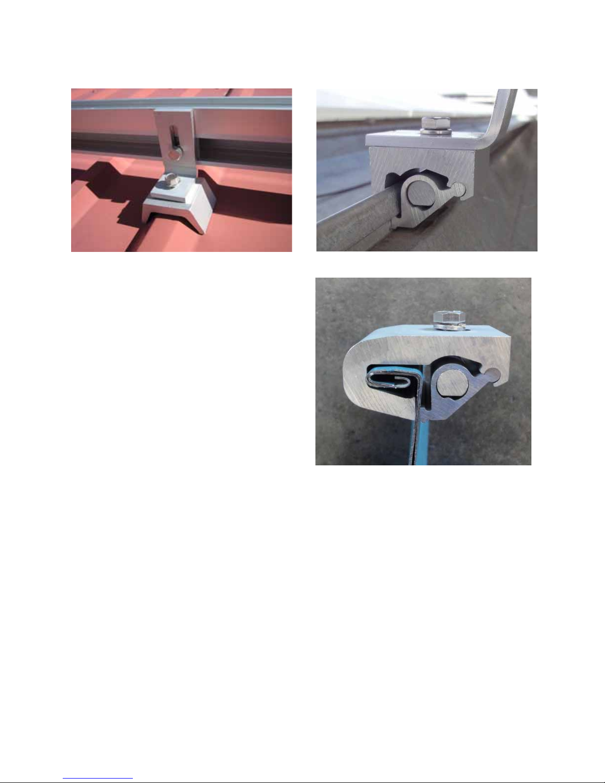
Fig 2.2 - Alternate SnapNrack Hardware
Corrugate Roof Block
Heavy Duty (HD) Stando and Base
Four-Hole Stando Base and Standard Stando
Standard Base Seam Clamp
Wide Base Seam Clamp
Hanger Bolt Clamp

| SnapNrackTM
SERIES 100
Roof MounT InSTallaTIon Manual
| 9
2.3 Obtain installer supplied tools
and materials
Make sure you have all the necessary
additional hardware components, tools, and
other material that are needed to complete
the installation. These include:
• Appropriateroofashingsforstando
installations
• Lagboltsandwashersforroof
attachments
• Waterproofroongsealant(suchas
Rainbuster) in a color to match the color
of the roof
• ½-inchbox/openendwrench
• 3/8-inchratchetwrenchwith½-inch
socket and short extension
• 3/8-inchtorquewrench
• Powerdrillwith3/16-inchx6-inchand
12-inch drill bits for lag bolt pilot holes
• 5/32-inchAllenkeyforlevelingspacers
on standos
• Toolsforattachinggroundinghardware
• Reciprocatingsaw(suchasaSawzall
or miter box) with correct blade for
trimming non-ferrous metal rails
• Metallefornishingtrimmedrails
• Chalklineandgreasepens(intwo
or three dierent colors) for marking
mounting locations on the roof material
• Tapemeasure
• Flatprybar
• Structuralplansforthebuildingwhen
available
• SnapNrack Rail Cutting Guide (Optional)
2.4 Survey the site
• Measuretheroofsurfacesanddevelop
an accurate drawing of the roof and any
obstacles such as chimneys and roof
vents.
• Ifplansareavailable,checktomake
sure that the plans match the nal
structure.
• Reviewtheshadingpatternacrossthe
roof surface from the residence itself,
from adjacent structures, and from
other nearby features such as trees.
• Identifyanyroofaccessareasor
keep-out areas as required by the local
jurisdiction.
• Conrmroofconstruction,type,and
condition.
• Assessroofraftersize,material,and
span to conrm that the structure is
sound and can support the additional
load of the array.
• Identifyanyconstructionanomalies
that may complicate the process of
locating rafters from the roof surface.
Figure 2.3 UEC Rail Cutting Guide
| SnapNrackTM
SERIES 100
Roof MounT InSTallaTIon Manual
10 |
• Measurethespacingbetweenthe
rafters.
• Ifyoundstructuralproblemssuch
as termite damage or cracked rafters
that may compromise the structure’s
integrity, consult a structural engineer.
Determine the design wind speed and site
specic conditions for the site and reference
the structural engineering tables (see section
13: Appendix) to determine the maximum
allowable rail span for this site.
If you are unsure about the local design
wind speed, consult with the local building
jurisdiction.
2.5 Lay out system on the roof
Using the information collected in the site
survey, complete a system layout showing
array location and distances from key roof
features. Include any information necessary
for the permitting process.
The following denitions are used to
describe array layout designs:
• Modulelength—themeasurement
along the longest side of the module
frame
• Modulewidth—themeasurement
along the shorter side of the module
frame
• Modulethickness—themeasurement
of the thickness of the module
Module Length
Module Width
Fig 2.4 - Layout of PV modules showing rail span

| SnapNrackTM
SERIES 100
Roof MounT InSTallaTIon Manual
| 11
Typically, PV modules are installed in portrait
mode, with the long side of the module
running up the roof slope and the rails
runninghorizontallyacrosstheroofperpen-
dicular to the roof rafters, which commonly
run down slope.
Arrays can also be installed in landscape
mode, with the modules oriented so that
theirlongedgerunshorizontallyacrossthe
roof and the rails run up the roof slope.
Landscape mode is typically used in cases
where the roof has been constructed with
structuralelementsrunninghorizontally
across the roof, but can also be used on
standard residential buildings for a variety of
reasons including to facilitate a convenient
layout.
When laying out the array, be sure to leave
space for the module clamps on the rails.
Module mid clamps (see Fig 2.1) are installed
between modules in a row and require .5 inch
of space between the modules.
Standard top-mount end clamps (see Fig 2.1)
require1½inchesofextrarailtoextendpast
the end of the module frame. If using the
UEC this does not apply.
The space between rows of modules is not
critical, but it is common for rows of modules
to be installed so that the modules are ush
with each other.
Submit array plans to local permitting
jurisdiction and proceed with the roof
layout only when all permits for the project
have been granted by the authority having
jurisdiction.
8CAUTION: If possible leave at least
3 to 4 feet around the outside
edges of the array to enable safe
access during the installation and
during maintenance and cleaning.
Transfer the array layout to the roof using
grease pens to mark the inside and outside
corners of the array.
Locate estimated rafter positions and mark
them in the array area with a dierent color
grease pen.
4 Common techniques for locating
rafters include looking under the
eaves, measuring from the ends
of the roof, using attic access, and
using electronic stud and rafter
nders.
Fig 2.5 - Portrait and Landscape Illustration
| SnapNrackTM
SERIES 100
Roof MounT InSTallaTIon Manual
12 |
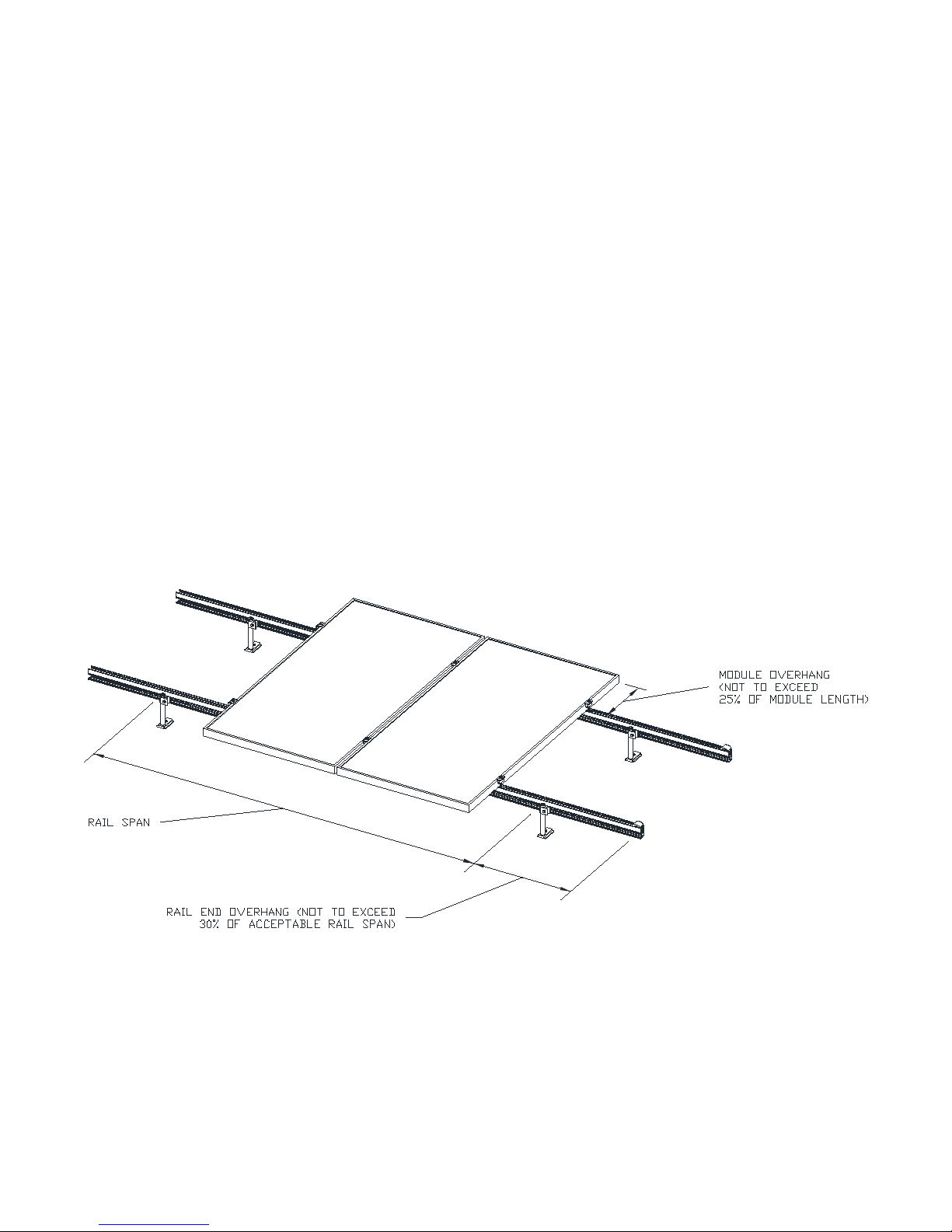
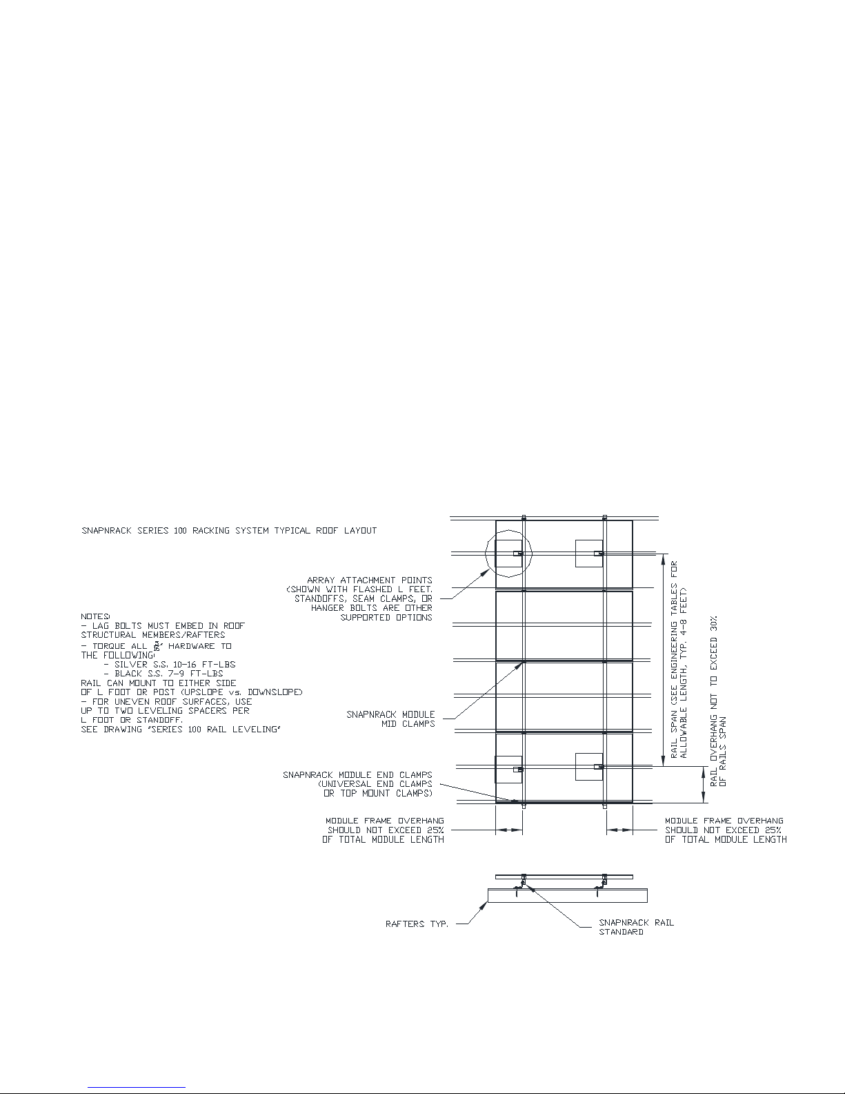
Transfer rail and estimated attachment
locations to the roof, noting that attachments
will be located at intersections of rails and
rafters.
Layout rails such that module frame ends do
not overhang mounting rails by more than
25% of total module frame length.
Verify that mounting rail spans are in
accordance with the rail span tables in
the Appendix at the back of this manual
(section 13).
Verify that rail ends do not overhang by a
distance greater than 30% of the acceptable
rail span specied in the same table.
Fig 2.6 - Location of rail end overhang and module overhang
| SnapNrackTM
SERIES 100
Roof MounT InSTallaTIon Manual
| 13
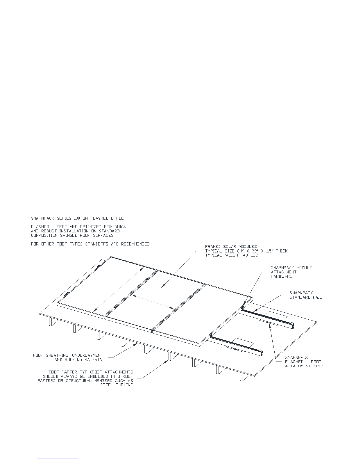
3.1 Introduction
Typically, using ashed L-feet to mount
PV modules enables a faster and simpler
installation than using standos, but the
L-foot type of mount can only be used on
composition roofs. Installations on shake
and tile roof surfaces, as well as thicker
composition roofs (that is, thicker than
1/8 inch), require the use of standos and
standard ashings.
For installations using standos, see section
4. For installations where the PV modules
will be installed tilted at an angle to the roof
surface, see section 6.
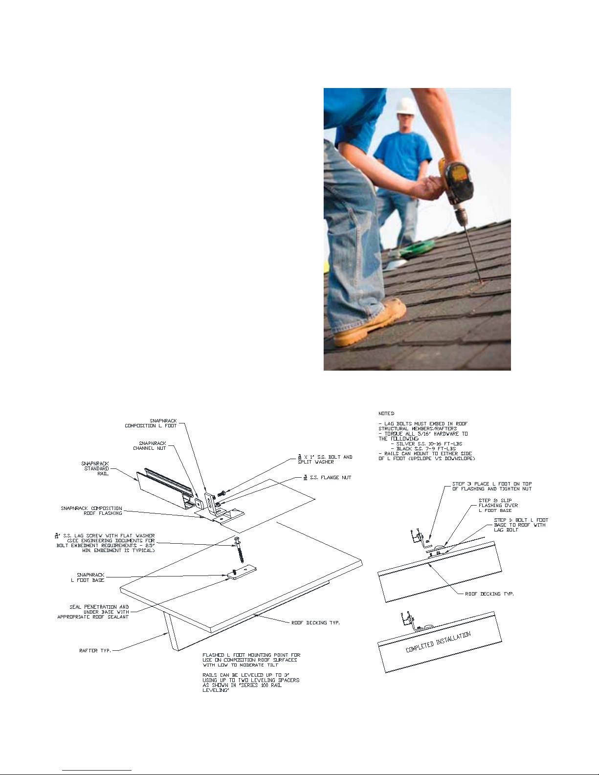
3. Flush mount on composition roofs (using L-feet)
Fig 3.0 - Flashed L-foot section view
Fig 3.1 - Typical PV module Roof Layout
| SnapNrackTM
SERIES 100
Roof MounT InSTallaTIon Manual
14 |
3.2 Locate
attachment points
The location of the attachment points for L-foot
mounts depends on the orientation of the
modules relative to the rafters as shown in this
diagram.
Using the array layout plans and the estimated
rafter locations, as described in the previous
section 2.5. Determine location of all attachment
points and mark the holes for each L-foot base.
3.3 Drill pilot holes
Conrm the location of the rafters by drilling
pilot holes into the roof at each of the identied
attachment points with a 3/16-inch pilot drill.
Fig 3.2 - Drill pilot holes
Fig 3.3 - L-foot mount assembly diagram

| SnapNrackTM
SERIES 100
Roof MounT InSTallaTIon Manual
| 15
Be sure to drill the hole deep enough to
penetrate the roof decking and enter the rafter
by1to1½inches.Ifthedrill pushes through at
this point, you have likely missed the rafter and
shouldmove½inchlaterallytowardwhere
you estimate the rafter to be and try again.
See Fig 3.3 for L-foot mount assembly details.
3.4 Secure base
Apply a bead of sealant to the underside of
the L-foot base and into pilot hole.
Screw 5/16-inch lag bolts with lag bolt washers
intothepilotholesandtightenwitha½-inch
socket. Using a socket adapter bit in a power
driver is a common method.
Make sure the lag bolts used are long
enough to embed a minimum of 2 inches
into the rafter to secure the L-foot base to the
roof. Refer to the lag bolt pullout chart for
apprpriate embedment.
4The required lag bolt length is based
on the roof thickness as measured
during the site evaluation.
4 Check that the lag bolts are secure
with a socket and ratchet wrench.
If the bolt spins out, you didn’t hit a rafter.
Apply sealant
L-foot base
Secure base to rafter
Move½inchlaterallytowardswhereyou
estimate the rafter to be and try again
starting with a new pilot hole.
3.5 Install ashing
Insert the stamped-steel roof ashing
over the L- foot base and underneath the
upslope shingle.
Fig 3.4 - Attaching L-foot base

| SnapNrackTM
SERIES 100
Roof MounT InSTallaTIon Manual
16 |
4Note: the L-foot base is dierent
from the stando base described in
section 4 of this manual. Make sure
you are using the correct part for
the type of roof on which you are
installing the array. See Fig 2.1.
3.6 Attach L-foot
Using the provided 5/16” serrated ange nut to
attach L-foot to L-foot base, securing the entire
assembly to a rafter. Repeat this procedure for
each L-foot base.
4The orientation of the L-foot on top
of the L-foot base is not critical and
can be varied based on installer
preference.
4Check all 5/16-inch bolt hardware is
tightened to the correct torque:
- Silver hardware - 10-16 ft-lbs.
- Black Hardware - 7-9 ft-lbs.
After installing all L-feet, go to section 7.
Install Flashing
Secure L-Foot to Base
Fig 3.6 - Installing Flashing & L-Foot
Completed Flashed L-Foot
| SnapNrackTM
SERIES 100
Roof MounT InSTallaTIon Manual
| 17
4.1 Introduction
Typically, standos are used for installations
on tile, shake, or special thick composition
roof types.
For installations on standard composition
roofs, use ashed L-feet as described in
section 3. For installations where the PV
modules will be installed tilted at an angle
to the roof surface, see section 6.
Diagram below shows stando mount
assembly details.
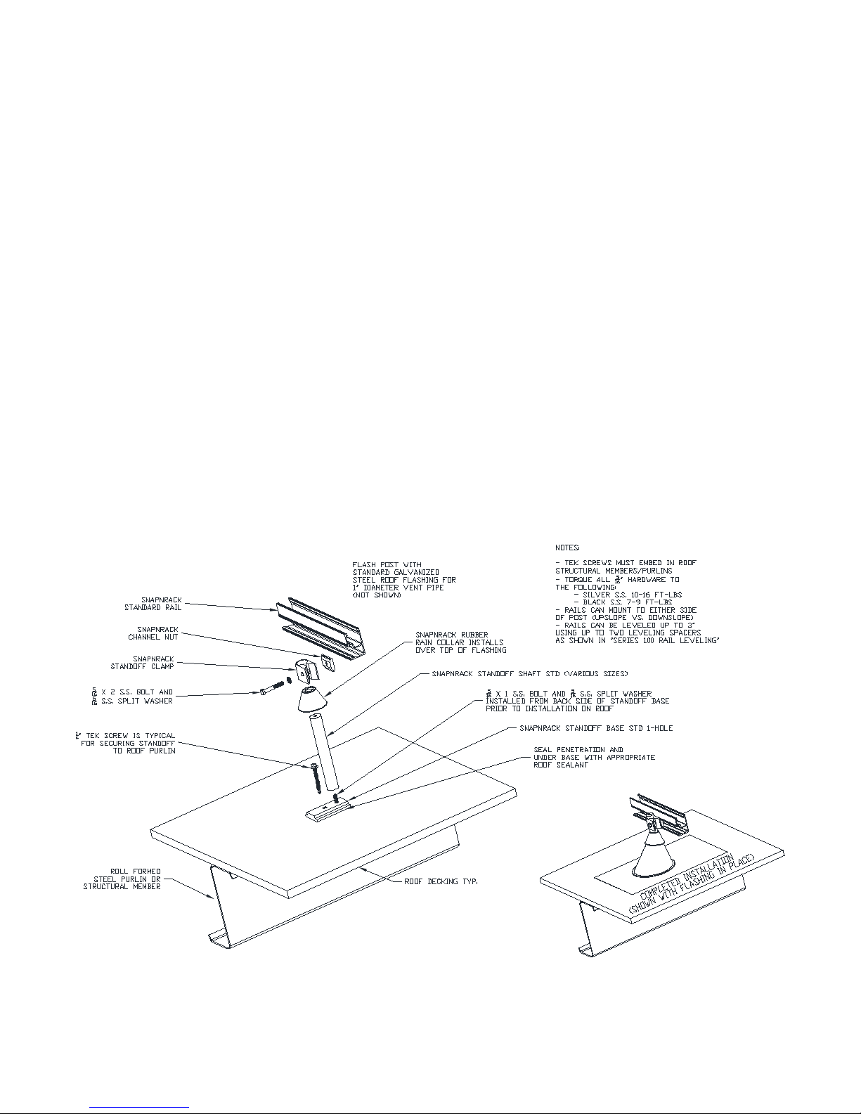
4. Flush mount on other roof types (using standos)
Fig 4.0 - Stando section view
Fig 4.1 - Stando mount assembly

| SnapNrackTM
SERIES 100
Roof MounT InSTallaTIon Manual
18 |
4.2 Determine type and size of
attachment and ashing
Based on the construction type, style of
the roof, and type of ashings to be used,
determinethesizeofstandosneeded.
As a general rule, standos should be
approximately2½inchestallerthanthecone
of the ashing selected for the roof type.
Some typical roof ashing heights are shown
in the list at the beginning of this section:
Roof Type Flashing Type Flashing Height Stando Height
Composition LowproleOatey 3inches 5½inches
Shake,Wood Standard 4½inches 7inches
GalvanizedSteel
FlatTile,Slate Dead-soft 6inches 8½inches
aluminum
S or Mission Tile Dead-soft aluminum 7 inches 10 inches
(Same as above except
lifted o roof)
Fig 4.2 - Stando installation using
Oatey ashing
4.3 Stando Base Options
SnapNrack Series 100 Mounting system has two alternative
stando bases that can be used when roof structures can
not accomodate the standard one-hole stando base. The
standard Stando shafts can be used with the Four-Hole
Stando Base when the roof structure uses laminate I-beams
that would be damaged by the one-hole stando base.
When higher load forces are expected or higher stando
heights are required because of roof geomtetry, the Heavy
Duty Stando Base and HD Stando Shaft can be used.
Fig 4.3 - HD Stando Installed
on Foam Roof

| SnapNrackTM
SERIES 100
Roof MounT InSTallaTIon Manual
| 19
Fig 4.4 - Four-Hole Stando Detail
Fig 4.5 - HD Stando Detail
Table of contents
Other SnapNrack Solar Panel manuals


Popular Solar Panel manuals by other brands


Van Der Valk
Van Der Valk ValkQuattro installation manual

optonica
optonica 7451 user manual

Solar Technology International
Solar Technology International PV Logic MHD Flexi user manual

AgfaPhoto
AgfaPhoto SP120 user manual

Westinghouse
Westinghouse WSolar60p user manual

solarwatt
solarwatt BLACK 60M STYLE installation instructions

Switch On
Switch On SOSLF 21 A1 operating instructions

Regulus
Regulus KPS11 Installation and operation instructions

Adventure Kings
Adventure Kings 120W Folding Solar Blanket user manual

Qcells
Qcells Q.POWER-G5.1 Installation and operation manual

Wetelux
Wetelux SL-SM-A-2 instruction manual

The Solar Trader
The Solar Trader 06003FX03 instruction manual