Snazio SZ132X User manual


Page 2 of 27
Published: Dec 2006
Copyright 2005 V One Multimedia Pte Ltd. All rights reserved. No part of this documentation may be
reproduced in any form or by any means or used to make any derivative work (such as translation,
transformation or adaptation) without permissions from V One Multimedia Pte Ltd.
V One Multimedia reserves the right to revise this documentation and to make changes in content from
time to time without obligation on the part of V One Multimedia Pte Ltd to provide notification of such
revisions or change.
V One Multimedia provides this documentation without any warranty of any kind, whether implied or
expressed, including, but not limited to, the implied warranties of merchantability and fitness for a particular
purpose, V One Multimedia may make improvements or changes in the products or software applications
described in this documentation at any time.
License
Agreement

Page 3 of 27
Contents
About This Guide 4
Important Instructions 5
Safety Information 5
Handling Cautions 5
1Introduction 6
What Is H.264 HDTV Receiver 6
Key Features 6
Before You Start 7
Package Contents 7
Front Panel Illustration 8
Rear Panel Illustration 10
Remote Control Tour 12
2Hardware Setup 14
Choosing a Connection 14
Audio System Connections 17
3Configuring H.264 HDTV Receiver 19
Powering On 19
Things to remember 19
Scanning Channels 19
Auto Scan 20
Manual Scanning 22
4System Options 23
TV System Setup 23
Setting Aspect Ratio 24
Setting Picture Quality 25
Setting Audio Options 25
Lock Password 26
Resetting Device 26
Firmware Upgrade 26
5Customer Support 27
World Wide Web 27
Online Chat Support 27

Page 4 of 27
About This Guide
Chapter 1, “Introduction”, describes the basic functionalities of hardware, an in depth look at the hardware
components available on the unit and the remote control.
If you have an idea and you want to need help in making Hardware Connections, skip to Chapter 2, “Hardware
Setup”.
If you have already made connections and you want to configure and search for the available channels, Chapter 3
“Configuring H.264 HDTV Receiver”, covers this.
If you have already scanned for available channels and want to explore the advanced options, Chapter 4 “System
Options” covers this.
Chapter5 “Customer Support” will help you to contact Tech Support department at V One Multimedia Pte Ltd.
This HDTV Receiver Family user guide covers the detail to setup and enjoy the High Definition Digital
Terrestrial TV. The User Guide explains each of the available option in detail.
Page 5 of 27
Important Instructions
Please read this section carefully in order to ensure your maximum safety while using the device. The cautionary items
will help you to prevent yourself completely from exposure to the risk of any electric shock and the safe operations of
the device.
Safety Information
To reduce the risk of fire or electric shock, do not expose this device to rain or moisture
Before operating the HDTV Receiver, check that the operating voltage indicated on the backside of the device is
identical with the voltage of your local power supply
Place the player on a flat, hard and subtle surface
Do not block the air vent. If the unit is in cabinet, allow about 2.5cm of free space all around the player for the
adequate ventilation
Do not expose your player to the extreme of temperature or humidity
The mechanical parts of the player contain self-lubricating bearings and must not be oiled or lubricated
When the player is switched to Standby mode, it is still consuming some power. To disconnect the system from the
power supply completely, remove the AC power plug from the wall socket
Handling Cautions
Before connecting other components to the H.264 HDTV Receiver, be sure to turn them all off.
Do not put any object on the receiver.
Disconnect the AC power cord from the AC outlet when you don’t intent to use the player for long periods of time
CAUTION: To reduce the risk of fire and electric
shock, don’t remove the cover (or back) of the unit.
Refer servicing only to qualified personnel
The lighting flash with arrowhead symbol, within an equilateral triangle,
is intended to alert the user to the presence of uninsulated “dangerous
voltage” within product’s enclosure that may be of sufficient magnitude
to constitute risk of electric shoc
k
The exclamation point within an equilateral triangle is intended to alert
the user to the presence of important operation and servicing
instructions in the literature accompanying the appliance.

Page 6 of 27
Introduction
Welcome and thank you for purchasing H.264 HDTV Receiver. Before you proceed to this product, we recommend
you read this user manual to get an overview of the product. This chapter provides an introduction to HDTV
Receiver and quick steps to configure the product.
What Is H.264 HDTV Receiver
H.264 HDTV is a future proof state of the art High Definition digital terrestrial receiver. Perfectly suited for receiving
the ever-growing digital terrestrial broadcasts from free to air channels, this product is complaint to both MPEG-2
and MPEG-4 AVC part 10 (H.264) which allows you to receive a wide spectrum of available digital channels either in
SD or HD format. Requiring only an aerial or indoor antenna, digital terrestrial broadcasting offers viewers not only
the ease of set up but consistency in AV quality. H.264 HDTV Receiver also provides you a vivid picture experience
with its ability to receive TV channels upto 1080i resolution which is five times higher resolution than a conventional
TV channel.
Key Features
Multi format TV Channel reception in MPEG-2 and MPEG-4 AVC Part 10 H.264 with decoding resolution up to
720p & 1080i
Receive HDTV & SDTV Free-To-Air TV Channels
Digital receiver which eliminates analogue transmission noise and ghost images
User Friendly EPG to receive latest TV information with support for Subtitling
Video Up scaling of SD TV channels to 720p / 1080i
Digital video output which completely eliminates analogue video noise
Digital audio output which supports 5.1 channel
Chapter
1

Page 7 of 27
Before You Start
Package Contents
H.264 HDTV Receiver
One Remote Controller
One pair of battery
One RCA cables (3) x 2 (1 yellow, 1 red and 1 white).
One user manual
Product Registration and Warranty card.
Install Batteries in the Remote Control
IF THE REMOTE CONTROL DOES NOT OPERATE PROPERLY
Check the polarity + - of the batteries
Check if the batteries are drained
Check if remote control sensor is blocked by obstacles
1
Open the battery cover on
the back of the Remote
Control
2
Insert the two AAA batteries.
Make sure that the polarities
(+ and -) are aligned
correctly. Replace the battery
cover

Page 8 of 27
Digital Receiver Description
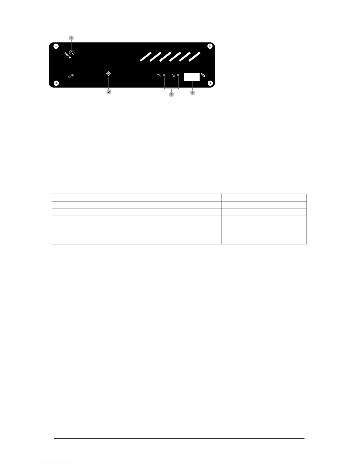
Front Panel Illustration
SZ132X Illustration
1: Power Button
When switched on (Down), the device is powered on and when switched off (Up), the device can be turned off
2: Remote Control Receiver
Remote Control signals are being received via this receiver. Remote Control must be within 4-6 meter range from this
part
3: VFD (LED Display)
VFD provides the device status information which displays Channel information and TV Mode
4: USB 2.0
Connect your USB storage device to update firmware
Page 9 of 27
1: External Infra Red
Connect provided IR cable with this jack. This additional RF is helpful to extend the range with cable and where the
STB can not be placed on front.
2: Remote Control Receiver
Remote Control signals are being received via this receiver. Remote Control must be within 4-6 meter range from this
part
3: LED
DTV and HD LED provide device status indication for the output resolution selected. Please take a look at the
following table to understand more about the LED status indicators
LED S TATUS FUNCTIONS
Power LED ON Device is Powered on
HD LED ON HD Output
HD LED OFF PAL/NTSC Output
DTV LED ON Device is operational
DTV LED BLINK Standby Mode
DTV LED OFF Device is processing IR commands
4: USB 2.0
Connect your USB storage device to update firmware
SZ130X, VA086X Illustration
Page 10 of 27
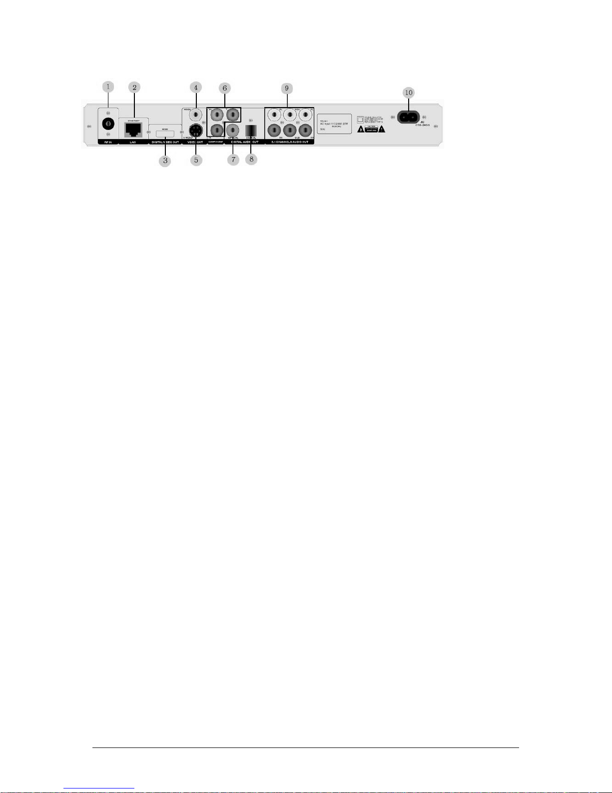
Rear Panel Illustration
SZ132X Illustration
1: Antenna Input
Connect your aerial input for receiving digital terrestrial transmission
2: 10/100 Mbps Ethernet RJ-45
Ethernet connection for future expandability
3: Digital Video Output
Connect DVI or HDMI (model dependent) output from the Digital Receiver to your High Definition
Television/LCD/Plasma/Projector
4: Composite Output
Connect Composite output to your analog television.
5: S-Video Output
Connect S-Video output from the Digital Receiver to your analog television for better video quality as compared to
composite. The real benefit of using S-Video connection is that it can reduce dot crawl, hanging dots and crawling
edges that appear usually on some colored objects. For example, text displayed on-screen using this connection is
noticeably sharper than composite.
6: Component Output
Connect component output from the Digital Receiver to your High Definition Television/LCD/Plasma/Projector.
Use component video output to take advantage of the superior picture found in Digital receiver as HDTV and
Progressive DVD or HD Video
7: S/PDIF Coaxial Digital Output
Coaxial digital audio output for digital audio appliances. Provides 5.1 or higher surround sound output
8: S/PDIF Optical Digital Output
Optical digital audio output for digital appliances. Provides 5.1 or higher surround sound output
9: 5.1 RCA Audio Outputs
Connect 5.1 surround audio system to enjoy home theatre sound even if you don’t have any digital audio appliance.
You can also connect your stereo system to the Digital Receiver
8: AC Input
Connect AC input with the Power Supply.

Page 11 of 27
1: Fan
Temperature controlling fan
2: Composite Output
Connect Composite output to your analog television.
3: RS – 232
For Debuging. Only for engineering use
4: Component Output
Connect component output from the Digital Receiver to your High Definition Television/LCD/Plasma/Projector.
5: Left/Right Stereo Audio Outputs
Connect Left and Right audio outputs from the rear of the HDTV Receiver to your stereo system
6: RF Loop
7: RF IN
Connect your aerial input for receiving digital terrestrial transmission
8: Digital Video Output
Connect HDMI output from the Digital Receiver to your High Definition Television/LCD/Plasma/Projector
9: S-Video Output
Connect S-Video output from the Digital Receiver to your analog television for better video quality.
10: S/PDIF Optical Digital Output
Optical digital audio output for digital appliances. Provides 5.1 or higher surround sound output
11: S/PDIF Coaxial Digital Output
Coaxial digital audio output for digital audio appliances. Provides 5.1 or higher surround sound output
12: USB
Connect your USB storage device to update firmware
13: 10/100 Mbps Ethernet RJ-45
Ethernet connection for future expandability
14: DC In
Connect your Power Adaptor with DC In on the HDTV Receiver
For Passthrough RF In incoming aerial signal to another tuner device like TV, VCR, another HDTV Receiver.
SZ130X , VA086X Illustration

Page 12 of 27
Remote Control Tour
1. Power (Standby)
2. Alphanumeric
3. Clear
4. Tv Mode
5. Setup
6. PBC
7. Up/Down Left/Right
8. Return
9. Skip Prev
10. Repeat
11. Info
12. Shuffle
13. Angle/Rotate
14. Select
15. Volume (+)
16. Volume (-)
17. Mute
18. Enter
19. Skip Next
20. Play
21. Search

Page 13 of 27
1: POWER (Standby) 15: VOLUME (+)
Toggle between operations / Standby Mode
2: ALPHANUMERIC INPUT 16: VOLUME (-)
Enters TV channel number or Decrease the volume
edit channel information
3: CLEAR 17: MUTE
Deletes the characters immediately Mute on/off
before the cursor
4: TV MODE (Video Output Selection) 18: ENTER
Switches the receiver’s output mode Activates the item you have selected
to Composite/S-Video, DVI/HDMI,
Component with assigned resolutions
5: SETUP 19: SKIP NEXT
Enters Setup menu of the receiver Jumps to the next favorite TV channel
6: PBC 20: PLAY
Displays channel number / OSD Displays favorite TV channel list
7: Up/Down Left/Right 21: SEARCH (SCAN)
Navigate the Setup functions Takes you to channel scan
8: RETURN
Returns to the last step. This button only
works in setup menu
9: SKIP PREV
Jumps to previous favorite channel
10:REPEAT
Allows you to quickly select the input source
For the Digital Receiver
11: INFO (EPG)
Displays the Program Guide
12: SHUFFLE (Picture Mode Selection)
Allows you to quickly select the TV Picture Mode
13: ANGLE/ROTATE (Picture Adjustment)
Allows you to do video adjustment
14: SELECT
Works with Alphanumeric keys to switch
between CAPSLOCK / 1-100 values for
text and numbers separately

Page 14 of 27
Hardware Setup
Choosing a Connection
The following chapter shows examples of connections commonly used to connect the HDTV Receiver with the
TV/HDTV and other components. There are a number of ways to connect the player to an AV system depending
on the type of TV and other AV equipment in your existing system.
Before
Connecting the HDTV Receiver
Always switch off the Receiver, TV, and other equipment before you connect or disconnect any cables.
Refer to the user’s manual of the additional AV system you are connecting for more information on those particular
components.
Connection to Antenna (Aerial Input)
Chapte
r
2
The Aerial input use must be able to receive UHF channel and the channel required must not be blocked.
Eg. In Singapore the Starhub Cable TV provider block all DVB-T signal broadcast by Mediacorp at this time,
so the Starhub antenna point cannot be used for this HDTV receiver.
Following options maybe use for Aerial input to HDTV receiver.

Page 15 of 27
Connection to a TV (Composite Video)
Connection to a TV (S-Video)
Connecting to your TV using an S-Video Cable.
You will enjoy high quality videos as S-Video carries the luminance and chrominance signals separately thus reducing
the chances of interference as compared to composite video
Connection to a TV (Component)
Component connections provide Progressive Scan option ensuring flicker-free image with highest possible quality. To
enjoy the advantages of progressive, your television set must be capable of handling Progressive Scanning.
1
Using video/audio cables, connect the
V
IDEO (yellow)/AUDIO (Red-FR &
White-FL) OUT terminals on the rear of
the player to the VIDEO IN terminals of
your TV
2
Turn on the HDTV Receiver and TV
3
Press the TV Mode button on your remote
control until the video signal from the
player appears on the TV screen
1
Using an S-Video cable, connect the S-
V
ideo OUT terminal on the rear of the
receiver to the S-VIDEO IN terminal of
your TV
2
Using the audio cables, connect the
A
UDIO (Red-FR & White-FL) OUT
terminals on the rear of the receiver to the
A
UDIO IN terminals of your TV. Turn on
the receiver and TV
3
Press the TV Mode button from the
remote control until the S-Video signal
from the receiver appears on your TV
screen

Page 16 of 27
Consult your TV User’s Manual to find out if your TV supports Progressive Scan. Depending on your TV, the
connection method may differ from the illustration used here.
Connection to a High Definition Displays (DVI / HDMI)
DVI VIDEO SPECIFICATIONS
H.264 HDTV Receiver provides multiple DVI / HDMI resolutions.
Depending on your TV/HDTV/Plasma/Projector, certain DVI resolutions may not work
DVI carries only video as compare to HDMI, so if you are using DVI, you will have to use with Analog or Digital
Audio cable for audio connection
1
Using component video cables, connect
the COMPONENT VIDEO OUT
terminals on the rear of the receiver to the
COMPONENT IN terminals of your TV
2
Using the AUDIO (Red-FR & White-
FL) OUT terminals on the rear of the
player to the AUDIO IN terminals of your
TV
3
Press the TV mode button from the
remote control until the component signal
from the receiver appears on the TV screen
1
Use the DVI / HDMI cable depending
on the model, connect the
DVI/HDMI OUT terminal on the
rear of the receiver to the DVI
/HDMI IN terminal of your TV
2
Use the Audio cables, connect the
A
UDIO (Red-FR & White-FL) OUT
terminals on the rear of the receiver to
the AUDIO IN terminals of your TV
if you are using a DVI output. Turn on
the receiver and your HDTV
3
Press the TV Mode button on your
remote control until the video signal
from the receiver appears on your TV
screen
Page 17 of 27
Audio System Connections
HDTV Receiver can either be connected with a two-channel analog stereo or Digital Audio Out on Optical and
Coaxial.
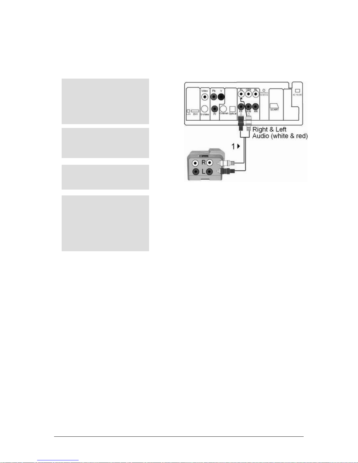
Connection to an Audio System (2 Channel Amplifier)
THINGS TO REMEMBER
Please turn the volume down when you turn on the Amplifier. Sudden loud sound may cause damage to the speakers
and your ears
The position of the terminals may vary depending on the Amplifier
Please refer to the User manual of the Amplifier
1
Using the audio cables, connect the
A
UDIO (Red-FR & White-FL)
OUT terminals on the rear of the
receiver to the AUDIO IN
terminals of the Amplifier
2
Using the video cables, connect the
receiver to the TV as described
earlier
3
Turn on the Receiver, TV and
A
mplifier
4
Press the input select button of the
A
mplifier to select external input in
order to hear sound from the
receiver. Refer to your Amplifier’s
user manual to set the Amplifiers
audio input
Page 18 of 27
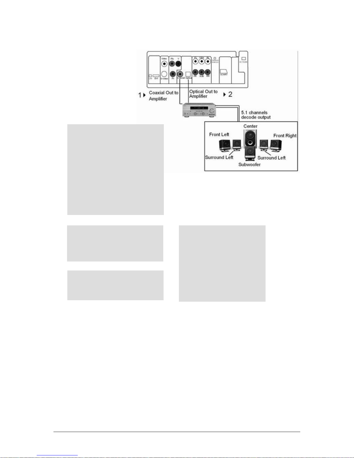
Connection to an Audio System (Multi-channel) for Dolby Digital/MPEG-2/DTS
THINGS TO REMEMBER
5.1 multi-channel Digital Surround via Digital connection is possible only if your receiver has a digital multi-channel
decoder. In case of DTS amplifier, please make sure to set the DTS to on in Audio Setup Menu while playing a DTS
disc. If it is set to off, sound will not be heard.
1
If using an optical cable, connect the
DIGITAL AUDIO OUT (OPTICAL)
terminal on the rear of the receiver to the
DIGITAL AUDIO IN terminal of the
A
mplifier. If using Coaxial cable, connect
the DIGITAL AUDIO OUT
(COAXIAL) terminal on the rear of the
receiver to the DIGITAL AUDIO IN
(COAXIAL) terminal of the Amplifier
2
Using the video cables, connect the
receiver to the TV as described earlier
3
Turn on the receiver, TV and Amplifier
4
Press the input select button of the
A
mplifier to select external input in
order to hear sound from the player.
Refer to your Amplifier’s user
manual to set the Amplifiers audio
input

Page 19 of 27
Configuring H.264 HDTV Receiver
This chapter provides you quick setup instructions to enjoy viewing HDTV. In this chapter we assume that you have
already done the Hardware Setup for connecting your Antenna and AV to the HDTV receiver, as explained in
Chapter 2.
Powering On
Connect the detachable Power Cord of the receiver to a socket
Power on by pressing the Power button on the front panel
THINGS TO REMEMBER
Important Note: If there is no video output, continue to press
TV Mode
button until video appears. Then use
Setup
button to select and save the appropriate video format. Please refer to
Chapter 4
for more information on available
output resolutions.
Scanning Channels
After Powering on the unit, you have to scan for all available SD and HD channels. H.264 HDTV Receiver provides
both Automatic and Manual search to scan all available free to air channels. For quick setup and channel scanning,
you should set the search channel option to “Auto” at the first scan after installing the digital receiver
Chapte
r
3

Page 20 of 27
Auto Scan
If your receiver is connected to an aerial and television, you can automatically search channels without additional
information. This is the easiest way for scanning all channels. Otherwise use the
Setup
button to perform following:
1:
Press the
Setup
button on the remote control to invoke the HDTV Receiver’s setup options.
2:
Navigate to the channel tab using the
Up/Down
keys on your remote control and press
Enter.
3:
Select
Search Channel
option and click OK.
4:
Select Scan option and press
Enter
5:
HDTV receiver will start receiving the channels automatically with a process indicator
This manual suits for next models
2
Table of contents


