Snell Advanced Media MV-805 User manual

www.s-a-m.com
User Manual
MV-805 IP Multiviewer
Software-based Turnkey IP Multiviewer Unit

MV-805 IP Multiviewer User Manual Top Level Contents
Issue1 Revision 1 Page 2 © 2018 SAM
Top Level Contents
1 About this Manual . . . . . . . . . . . . . . . . . . . . . . . . . . . . . . . . . . . . . . . . . . . . . . . . . . . . 6
2 Safety Information. . . . . . . . . . . . . . . . . . . . . . . . . . . . . . . . . . . . . . . . . . . . . . . . . . . . 7
3 Product Overview . . . . . . . . . . . . . . . . . . . . . . . . . . . . . . . . . . . . . . . . . . . . . . . . . . . 12
4 Unit Hardware . . . . . . . . . . . . . . . . . . . . . . . . . . . . . . . . . . . . . . . . . . . . . . . . . . . . . . 25
5 Hardware Installation . . . . . . . . . . . . . . . . . . . . . . . . . . . . . . . . . . . . . . . . . . . . . . . . 38
6 RollCall Templates . . . . . . . . . . . . . . . . . . . . . . . . . . . . . . . . . . . . . . . . . . . . . . . . . . 46
7 Getting Started 1 - Unit Settings (RollCall Template). . . . . . . . . . . . . . . . . . . . . . . 77
8 Getting Started 2 - IP Routing (Orbit) . . . . . . . . . . . . . . . . . . . . . . . . . . . . . . . . . . . 89
9 Getting Started 3 - Design/Layout of Video Wall (Orbit) . . . . . . . . . . . . . . . . . . . 108
10 Maintenance. . . . . . . . . . . . . . . . . . . . . . . . . . . . . . . . . . . . . . . . . . . . . . . . . . . . . . 121
Appendix A Specification for Turnkey MV-805 . . . . . . . . . . . . . . . . . . . . . . . . . . . . 129
Appendix B Terminology. . . . . . . . . . . . . . . . . . . . . . . . . . . . . . . . . . . . . . . . . . . . . . 134

MV-805 IP Multiviewer User Manual Contents
Issue1 Revision 1 Page 3 © 2018 SAM
Contents
1 About this Manual . . . . . . . . . . . . . . . . . . . . . . . . . . . . . . . . . . . . . . . . . . . . . . . . . . . . 6
1.1 Contact Details . . . . . . . . . . . . . . . . . . . . . . . . . . . . . . . . . . . . . . . . . . . . . . . . . . . 6
1.2 Copyright and Disclaimer . . . . . . . . . . . . . . . . . . . . . . . . . . . . . . . . . . . . . . . . . . . 6
1.3 Trademarks . . . . . . . . . . . . . . . . . . . . . . . . . . . . . . . . . . . . . . . . . . . . . . . . . . . . . . 6
2 Safety Information. . . . . . . . . . . . . . . . . . . . . . . . . . . . . . . . . . . . . . . . . . . . . . . . . . . . 7
2.1 Warnings and Precautions . . . . . . . . . . . . . . . . . . . . . . . . . . . . . . . . . . . . . . . . . . 9
2.1.1 Explanation of Safety Symbols . . . . . . . . . . . . . . . . . . . . . . . . . . . . . . . . . . . 9
2.1.2 Safety Warnings . . . . . . . . . . . . . . . . . . . . . . . . . . . . . . . . . . . . . . . . . . . . . . 9
2.1.3 Fiber Input/Output Modules. . . . . . . . . . . . . . . . . . . . . . . . . . . . . . . . . . . . . 10
2.1.4 Lithium Batteries . . . . . . . . . . . . . . . . . . . . . . . . . . . . . . . . . . . . . . . . . . . . . .11
2.1.5 Equipment Mains Supply Voltage . . . . . . . . . . . . . . . . . . . . . . . . . . . . . . . . .11
2.1.6 Electrostatic Damage . . . . . . . . . . . . . . . . . . . . . . . . . . . . . . . . . . . . . . . . . .11
2.2 Power Cords . . . . . . . . . . . . . . . . . . . . . . . . . . . . . . . . . . . . . . . . . . . . . . . . . . . . .11
2.3 Safety and EMC Standards. . . . . . . . . . . . . . . . . . . . . . . . . . . . . . . . . . . . . . . . . .11
3 Product Overview . . . . . . . . . . . . . . . . . . . . . . . . . . . . . . . . . . . . . . . . . . . . . . . . . . . 12
3.1 MV-805 Features and Benefits . . . . . . . . . . . . . . . . . . . . . . . . . . . . . . . . . . . . . . 13
3.2 Order Codes . . . . . . . . . . . . . . . . . . . . . . . . . . . . . . . . . . . . . . . . . . . . . . . . . . . . 14
3.3 Functionality Architecture and Signal Flow . . . . . . . . . . . . . . . . . . . . . . . . . . . . . 15
3.3.1 Input and Output Connections . . . . . . . . . . . . . . . . . . . . . . . . . . . . . . . . . . 15
3.3.2 Turnkey MV-805 Hardware-Optimized Software. . . . . . . . . . . . . . . . . . . . . 16
3.3.3 Network Redundancy . . . . . . . . . . . . . . . . . . . . . . . . . . . . . . . . . . . . . . . . . 17
3.3.4 IP Streams and Flows . . . . . . . . . . . . . . . . . . . . . . . . . . . . . . . . . . . . . . . . . 17
3.4 Input Video Signal Selection . . . . . . . . . . . . . . . . . . . . . . . . . . . . . . . . . . . . . . . . 18
3.4.1 MV-805 and SAM IP Routing System . . . . . . . . . . . . . . . . . . . . . . . . . . . . . 18
3.4.2 Non-SAM IP Routing. . . . . . . . . . . . . . . . . . . . . . . . . . . . . . . . . . . . . . . . . . 19
3.5 Network Topologies. . . . . . . . . . . . . . . . . . . . . . . . . . . . . . . . . . . . . . . . . . . . . . . 20
3.6 Video Timing Reference . . . . . . . . . . . . . . . . . . . . . . . . . . . . . . . . . . . . . . . . . . . 22
3.7 Software Compatibility Matrix . . . . . . . . . . . . . . . . . . . . . . . . . . . . . . . . . . . . . . . 22
3.8 Configuration Overview. . . . . . . . . . . . . . . . . . . . . . . . . . . . . . . . . . . . . . . . . . . . 22
3.8.1 Unit Settings (RollCall Templates). . . . . . . . . . . . . . . . . . . . . . . . . . . . . . . . 22
3.8.2 Unit IP Routing Settings in the IP Routing System . . . . . . . . . . . . . . . . . . . 22
3.8.3 Design/Layout of Video Wall . . . . . . . . . . . . . . . . . . . . . . . . . . . . . . . . . . . . 22
3.9 Data Packets. . . . . . . . . . . . . . . . . . . . . . . . . . . . . . . . . . . . . . . . . . . . . . . . . . . . 24
3.10 Terminology. . . . . . . . . . . . . . . . . . . . . . . . . . . . . . . . . . . . . . . . . . . . . . . . . . . . 24
4 Unit Hardware . . . . . . . . . . . . . . . . . . . . . . . . . . . . . . . . . . . . . . . . . . . . . . . . . . . . . . 25
4.1 Unpacking . . . . . . . . . . . . . . . . . . . . . . . . . . . . . . . . . . . . . . . . . . . . . . . . . . . . . . 25
4.2 Unit Chassis Overview . . . . . . . . . . . . . . . . . . . . . . . . . . . . . . . . . . . . . . . . . . . . 26
4.3 Unit Front Panel . . . . . . . . . . . . . . . . . . . . . . . . . . . . . . . . . . . . . . . . . . . . . . . . . 27
4.3.1 Front Control Panel. . . . . . . . . . . . . . . . . . . . . . . . . . . . . . . . . . . . . . . . . . . 27
4.3.2 Front Hard Drive Bays. . . . . . . . . . . . . . . . . . . . . . . . . . . . . . . . . . . . . . . . . 30
4.4 Unit Rear Panel. . . . . . . . . . . . . . . . . . . . . . . . . . . . . . . . . . . . . . . . . . . . . . . . . . 31
4.4.1 PSU Modules and AC Power Inlets. . . . . . . . . . . . . . . . . . . . . . . . . . . . . . . 32
4.4.2 Server Motherboard I/O. . . . . . . . . . . . . . . . . . . . . . . . . . . . . . . . . . . . . . . . 33
4.4.3 High-Performance Network Adapter(s). . . . . . . . . . . . . . . . . . . . . . . . . . . . 35
4.4.4 MV-805 Network Interfaces. . . . . . . . . . . . . . . . . . . . . . . . . . . . . . . . . . . . . 36
4.5 Power Supply Units. . . . . . . . . . . . . . . . . . . . . . . . . . . . . . . . . . . . . . . . . . . . . . . 37
4.6 Fuses. . . . . . . . . . . . . . . . . . . . . . . . . . . . . . . . . . . . . . . . . . . . . . . . . . . . . . . . . . 37
5 Hardware Installation . . . . . . . . . . . . . . . . . . . . . . . . . . . . . . . . . . . . . . . . . . . . . . . . 38
5.1 Environmental Considerations . . . . . . . . . . . . . . . . . . . . . . . . . . . . . . . . . . . . . . 38
5.2 Chassis Ventilation . . . . . . . . . . . . . . . . . . . . . . . . . . . . . . . . . . . . . . . . . . . . . . . 39
5.3 Preparing the Unit and the Rack . . . . . . . . . . . . . . . . . . . . . . . . . . . . . . . . . . . . . 40
5.3.1 Location in Rack . . . . . . . . . . . . . . . . . . . . . . . . . . . . . . . . . . . . . . . . . . . . . 40
5.4 Rack Mounting . . . . . . . . . . . . . . . . . . . . . . . . . . . . . . . . . . . . . . . . . . . . . . . . . . 41
5.4.1 Mounting the MV-805 into a Rack. . . . . . . . . . . . . . . . . . . . . . . . . . . . . . . . 41

MV-805 IP Multiviewer User Manual Contents
Issue1 Revision 1 Page 4 © 2018 SAM
5.4.2 Connecting Up in a Rack. . . . . . . . . . . . . . . . . . . . . . . . . . . . . . . . . . . . . . . 42
5.4.3 Powering . . . . . . . . . . . . . . . . . . . . . . . . . . . . . . . . . . . . . . . . . . . . . . . . . . . 43
5.5 Unit Starting Up. . . . . . . . . . . . . . . . . . . . . . . . . . . . . . . . . . . . . . . . . . . . . . . . . . 44
5.5.1 Starting . . . . . . . . . . . . . . . . . . . . . . . . . . . . . . . . . . . . . . . . . . . . . . . . . . . . 44
5.5.2 Checking Multiviewer Output Picture . . . . . . . . . . . . . . . . . . . . . . . . . . . . . 44
5.6 Unit Shutdown. . . . . . . . . . . . . . . . . . . . . . . . . . . . . . . . . . . . . . . . . . . . . . . . . . . 45
5.6.1 Shutdown . . . . . . . . . . . . . . . . . . . . . . . . . . . . . . . . . . . . . . . . . . . . . . . . . . 45
5.6.2 Forced Shutdown . . . . . . . . . . . . . . . . . . . . . . . . . . . . . . . . . . . . . . . . . . . . 45
5.7 Unit Configuration Stages . . . . . . . . . . . . . . . . . . . . . . . . . . . . . . . . . . . . . . . . . . 45
6 RollCall Templates . . . . . . . . . . . . . . . . . . . . . . . . . . . . . . . . . . . . . . . . . . . . . . . . . . 46
6.1 Introduction to the RollCall MV-805 Template Screen. . . . . . . . . . . . . . . . . . . . . 47
6.2 System-Setup Template . . . . . . . . . . . . . . . . . . . . . . . . . . . . . . . . . . . . . . . . . . . 49
6.2.1 Product box. . . . . . . . . . . . . . . . . . . . . . . . . . . . . . . . . . . . . . . . . . . . . . . . . 51
6.2.2 System Reset box. . . . . . . . . . . . . . . . . . . . . . . . . . . . . . . . . . . . . . . . . . . . 51
6.2.3 Network Settings box . . . . . . . . . . . . . . . . . . . . . . . . . . . . . . . . . . . . . . . . . 52
6.2.4 RollCall Settings box. . . . . . . . . . . . . . . . . . . . . . . . . . . . . . . . . . . . . . . . . . 54
6.2.5 IP Fabric box. . . . . . . . . . . . . . . . . . . . . . . . . . . . . . . . . . . . . . . . . . . . . . . . 56
6.2.6 “Router Controller Settings” box . . . . . . . . . . . . . . . . . . . . . . . . . . . . . . . . . 59
6.2.7 Information box . . . . . . . . . . . . . . . . . . . . . . . . . . . . . . . . . . . . . . . . . . . . . . 61
6.2.8 Service Reset to Effect Settings Changes in the System-Setup Template . 62
6.3 Layout Template . . . . . . . . . . . . . . . . . . . . . . . . . . . . . . . . . . . . . . . . . . . . . . . . . 63
6.4 TSL Template . . . . . . . . . . . . . . . . . . . . . . . . . . . . . . . . . . . . . . . . . . . . . . . . . . . 64
6.5 Timer Control Template. . . . . . . . . . . . . . . . . . . . . . . . . . . . . . . . . . . . . . . . . . . . 66
6.6 Timer Request Protocol Template. . . . . . . . . . . . . . . . . . . . . . . . . . . . . . . . . . . . 68
6.7 Destination Spigot Template . . . . . . . . . . . . . . . . . . . . . . . . . . . . . . . . . . . . . . . . 69
6.7.1 Manual Setting of Multicast Flow. . . . . . . . . . . . . . . . . . . . . . . . . . . . . . . . . 72
6.8 Source Spigot Template . . . . . . . . . . . . . . . . . . . . . . . . . . . . . . . . . . . . . . . . . . . 73
6.8.1 Changing Source Flow . . . . . . . . . . . . . . . . . . . . . . . . . . . . . . . . . . . . . . . . 75
6.9 Reset Template . . . . . . . . . . . . . . . . . . . . . . . . . . . . . . . . . . . . . . . . . . . . . . . . . . 76
7 Getting Started 1 - Unit Settings (RollCall Template). . . . . . . . . . . . . . . . . . . . . . . 77
7.1 How to Connect RollCall Control Panel to the MV-805 unit . . . . . . . . . . . . . . . . 78
7.1.1 Preparation . . . . . . . . . . . . . . . . . . . . . . . . . . . . . . . . . . . . . . . . . . . . . . . . . 78
7.1.2 Connecting RollCall Control Panel . . . . . . . . . . . . . . . . . . . . . . . . . . . . . . . 78
7.2 Initial MV-805 Unit Configuration with RollCall . . . . . . . . . . . . . . . . . . . . . . . . . . 81
7.2.1 Setting Up the Host Name. . . . . . . . . . . . . . . . . . . . . . . . . . . . . . . . . . . . . . 81
7.2.2 Setting Up the Control Network Interface(s) . . . . . . . . . . . . . . . . . . . . . . . . 82
7.2.3 Setting Up the Media IP Fabric Network Interface(s) . . . . . . . . . . . . . . . . . 83
7.2.4 Setting Up the RollCall Settings . . . . . . . . . . . . . . . . . . . . . . . . . . . . . . . . . 84
7.2.5 Assigning Network Interfaces as Fabric A or B. . . . . . . . . . . . . . . . . . . . . . 84
7.2.6 Getting the Multiviewer Input Signal Names . . . . . . . . . . . . . . . . . . . . . . . . 85
7.2.7 Adding some Information Text. . . . . . . . . . . . . . . . . . . . . . . . . . . . . . . . . . . 86
7.2.8 Apply Initial Unit Settings (via a Service Reset) . . . . . . . . . . . . . . . . . . . . . 86
7.3 Shutting Down the Unit . . . . . . . . . . . . . . . . . . . . . . . . . . . . . . . . . . . . . . . . . . . . 87
7.4 Connect up Network and Power onto the Unit . . . . . . . . . . . . . . . . . . . . . . . . . . 88
8 Getting Started 2 - IP Routing (Orbit) . . . . . . . . . . . . . . . . . . . . . . . . . . . . . . . . . . . 89
8.1 Configuring Orbit for Discovering Out-of-Band Devices . . . . . . . . . . . . . . . . . . . 90
8.2 Set the MV-805 ‘Device Name’ . . . . . . . . . . . . . . . . . . . . . . . . . . . . . . . . . . . . . . 92
8.3 Find which Video Router Source and Destination Ports to Use . . . . . . . . . . . . . 95
8.3.1 To Find Used Router Source Ports . . . . . . . . . . . . . . . . . . . . . . . . . . . . . . . 95
8.3.2 To Find Used Router Destination Ports. . . . . . . . . . . . . . . . . . . . . . . . . . . . 96
8.3.3 Establish Port Number Ranges for the MV-805 . . . . . . . . . . . . . . . . . . . . . 97
8.4 Assign Router Ports to the MV-805. . . . . . . . . . . . . . . . . . . . . . . . . . . . . . . . . . . 98
8.5 Set Up Multiviewer Display Outputs (Source Flows). . . . . . . . . . . . . . . . . . . . . 101
8.6 Multiviewer Display Output . . . . . . . . . . . . . . . . . . . . . . . . . . . . . . . . . . . . . . . . 104
8.6.1 Default Multiviewer Display Output . . . . . . . . . . . . . . . . . . . . . . . . . . . . . . 104
8.6.2 Viewing Multiviewer Output. . . . . . . . . . . . . . . . . . . . . . . . . . . . . . . . . . . . 104
8.6.3 Connecting Multiviewer Inputs . . . . . . . . . . . . . . . . . . . . . . . . . . . . . . . . . 104

MV-805 IP Multiviewer User Manual Contents
Issue1 Revision 1 Page 5 © 2018 SAM
8.6.4 Default Multiviewer Video Wall with Video on Video Tiles. . . . . . . . . . . . . 105
8.6.5 Orbit IP Multiviewer Projects. . . . . . . . . . . . . . . . . . . . . . . . . . . . . . . . . . . 105
8.7 Making Routes in a SAM IP Routing System . . . . . . . . . . . . . . . . . . . . . . . . . . 106
9 Getting Started 3 - Design/Layout of Video Wall (Orbit) . . . . . . . . . . . . . . . . . . . 108
9.1 Orbit IP Multiviewer Projects . . . . . . . . . . . . . . . . . . . . . . . . . . . . . . . . . . . . . . . 109
9.1.1 Number of and Type of Multiviewer Inputs and Outputs . . . . . . . . . . . . . . 109
9.1.2 Creating a New Project . . . . . . . . . . . . . . . . . . . . . . . . . . . . . . . . . . . . . . . 109
9.1.3 Main Menu - Multiviewer Drop-Down Menu Items . . . . . . . . . . . . . . . . . . .110
9.1.4 Tools Menu - Remotes Dialog - No ‘Restore’ . . . . . . . . . . . . . . . . . . . . . . .110
9.2 Basic Video Wall . . . . . . . . . . . . . . . . . . . . . . . . . . . . . . . . . . . . . . . . . . . . . . . . .112
9.3 Configuring Alarms . . . . . . . . . . . . . . . . . . . . . . . . . . . . . . . . . . . . . . . . . . . . . . .113
9.3.1 Input Alarms . . . . . . . . . . . . . . . . . . . . . . . . . . . . . . . . . . . . . . . . . . . . . . . .113
9.4 TSL Support . . . . . . . . . . . . . . . . . . . . . . . . . . . . . . . . . . . . . . . . . . . . . . . . . . . .117
9.4.1 TSL Protocol Tally Settings . . . . . . . . . . . . . . . . . . . . . . . . . . . . . . . . . . . . .117
9.4.2 Specifying Multiviewer TSL Tally Mode. . . . . . . . . . . . . . . . . . . . . . . . . . . .117
9.4.3 Specifying Index Parameters for each UMD . . . . . . . . . . . . . . . . . . . . . . . .118
9.5 On-screen Input Status Information Lines. . . . . . . . . . . . . . . . . . . . . . . . . . . . . 120
10 Maintenance. . . . . . . . . . . . . . . . . . . . . . . . . . . . . . . . . . . . . . . . . . . . . . . . . . . . . . 121
10.1 Software Upgrade . . . . . . . . . . . . . . . . . . . . . . . . . . . . . . . . . . . . . . . . . . . . . . 121
10.1.1 The Upgrade Package . . . . . . . . . . . . . . . . . . . . . . . . . . . . . . . . . . . . . . 121
10.1.2 Upgrade Procedure. . . . . . . . . . . . . . . . . . . . . . . . . . . . . . . . . . . . . . . . . 121
10.1.3 Stage 1: Add Upgrade Package to RollCall. . . . . . . . . . . . . . . . . . . . . . . 122
10.1.4 Stage 2: Install the Software Release on the Multiviewer Unit . . . . . . . . 124
10.2 PSU Module Replacement . . . . . . . . . . . . . . . . . . . . . . . . . . . . . . . . . . . . . . . 128
10.3 SSD Replacement. . . . . . . . . . . . . . . . . . . . . . . . . . . . . . . . . . . . . . . . . . . . . . 128
10.4 Cooling Fan Replacement. . . . . . . . . . . . . . . . . . . . . . . . . . . . . . . . . . . . . . . . 128
Appendix A Specification for Turnkey MV-805 . . . . . . . . . . . . . . . . . . . . . . . . . . . . 129
A.1 COTS Hardware Platform for the Turnkey MV-805 . . . . . . . . . . . . . . . . . . . . . 129
A.2 Physical. . . . . . . . . . . . . . . . . . . . . . . . . . . . . . . . . . . . . . . . . . . . . . . . . . . . . . . 129
A.3 Operating Environment. . . . . . . . . . . . . . . . . . . . . . . . . . . . . . . . . . . . . . . . . . . 130
A.4 Electrical . . . . . . . . . . . . . . . . . . . . . . . . . . . . . . . . . . . . . . . . . . . . . . . . . . . . . . 130
A.5 Regulatory Compliance. . . . . . . . . . . . . . . . . . . . . . . . . . . . . . . . . . . . . . . . . . . 130
A.6 Inputs . . . . . . . . . . . . . . . . . . . . . . . . . . . . . . . . . . . . . . . . . . . . . . . . . . . . . . . . 131
A.7 Outputs . . . . . . . . . . . . . . . . . . . . . . . . . . . . . . . . . . . . . . . . . . . . . . . . . . . . . . . 131
A.8 Network Connections . . . . . . . . . . . . . . . . . . . . . . . . . . . . . . . . . . . . . . . . . . . . 132
A.9 Default Ethernet IP Addresses . . . . . . . . . . . . . . . . . . . . . . . . . . . . . . . . . . . . . 132
A.10 On-Screen Monitoring. . . . . . . . . . . . . . . . . . . . . . . . . . . . . . . . . . . . . . . . . . . 133
Appendix B Terminology. . . . . . . . . . . . . . . . . . . . . . . . . . . . . . . . . . . . . . . . . . . . . . 134
B.1 IP Routing Terminology . . . . . . . . . . . . . . . . . . . . . . . . . . . . . . . . . . . . . . . . . . 134
B.2 Multiviewer Video Walls . . . . . . . . . . . . . . . . . . . . . . . . . . . . . . . . . . . . . . . . . . 137

MV-805 IP Multiviewer User Manual Contact Details About this Manual 1.1
Issue1 Revision 1 Page 6 © 2018 SAM
1 About this Manual
Thank you for purchasing your new MV-805 IP Multiviewer unit.
This user manual describes how to install, configure and operate the MV-805, and provides
any relevant safety information. If you have any questions regarding the installation and setup
of your product, please contact SAM Customer Support.
1.1 Contact Details
Customer Support
For details of our Regional Customer Support Offices and contact details please visit the SAM
web site and navigate to Support/247-Support.
https://s-a-m.com/support/247-support-contact-details/
Customers with a support contract should call their personalized number, which can be found
in their contract, and be ready to provide their contract number and details.
1.2 Copyright and Disclaimer
Copyright protection claimed includes all forms and matters of copyrightable material and
information now allowed by statutory or judicial law or hereinafter granted, including without
limitation, material generated from the software programs which are displayed on the screen
such as icons, screen display looks etc.
Information in this manual and any software are subject to change without notice and does
not represent a commitment on the part of SAM. Any software described in this manual is
furnished under a license agreement and can not be reproduced or copied in any manner
without prior agreement with SAM, or their authorized agents.
Reproduction or disassembly of embedded computer programs or algorithms is prohibited.
No part of this publication can be transmitted or reproduced in any form or by any means,
electronic or mechanical, including photocopy, recording or any information storage and
retrieval system, without permission being granted, in writing, by the publishers or their
authorized agents.
SAM operates a policy of continuous improvement and development. SAM reserves the right
to make changes and improvements to any of the products described in this document
without prior notice.
1.3 Trademarks
Microsoft,Microsoft Windows and Windows are either registeredtrademarks or trademarks of
Microsoft Corporation in the United States and/or other countries.
All other trademarks or registered trademarks are the property of their respective owners.

MV-805 IP Multiviewer User Manual Safety Information
Issue1 Revision 1 Page 7 © 2018 SAM
2 Safety Information
Erklärung der Sicherheitssymbole
Dieses Symbol weist den Benutzer auf wichtige Informationen
hin, die in der begleitenden Dokumentation enthalten sind.
Dieses Symbolzeigt an, dass gefährliche Spannung vorhanden ist.
Es befinden sich keine vom Benutzer zu wartenden Teile im Geräteinneren.
Dieses Gerät sollte nur von geschultem Personal gewartet werden
·Um das Risiko eines Elektroschocks zu reduzieren, setzen Sie das
Gerät weder Regen noch Feuchtigkeit aus.
·Stellen Sie immer sicher, dass das Gerät ordnungsgemäß geerdet
und verkabelt ist.
·Dieses Equipment muss an eine Netzsteckdose mit Schutzleiter
angeschlossen werden und einen zuverlässig identifizierbaren Nullleiter haben.
·Die Netzsteckdose sollte nahe beim Gerät und einfach zugänglich sein.
Sicherheits-Warnhinweise
D
!
Die angeführten Service-/Reparatur-Anweisungen sind
ausschließlich von qualifiziertem Service-Personal
auszuführen. Um das Risiko eines lektroschocks zu
reduzieren, führen Sie ausschließlich die im
Benutzerhandbuch eschriebenen Anweisungen aus,
es sei denn,Sie haben die entsprechende Qualifikation.
Wenden Sie sich in allen Service-Fragen an qualifiziertes Personal.
!ACHTUNG
Gefahr von Elektroschocks.
Abdeckungen nicht entfernen
Keine vom Benutzer zu wartende Teile
Wenden Sie sich ausschließlich
an q ua lifiz ie rt es Pe rson al
Explicación de los Símbolos de Seguridad
Éste símbolo refiere al usuario información importante contenida
en la literatura incluida.Referirse al manual.
Éste símbolo indica que voltajes peligrosos están presentes en el interior.
No hay elementos accesibles al usuario dentro.
Esta unidad sólo debería ser tratada por personal cualificado.
Las instrucciones de servicio cuando sean dadas, son
sólo para uso de personal cualificado.Para reducir el
riesgo de choque eléctrico no llevar a cabo ninguna
operación de servicio aparte de las contenidas en las
instrucciones de operación, a menos que se esté
cualificado para realizarlas.
Referir todo el trabajo de servicio a personal cualificado.
·
Para reducir el riesgo de choque eléctrico, no exponer este equipo
a la lluvia o humedad.
·
Siempre asegurarse de que la unidad está propiamente conectada a
tierra y que las conexiones de alimentación están hechas correctamente.
·
Este equipo debe ser alimentado desde un sistema de alimentación
con conexión a TIERRA y teniendo una conexión neutra fácilmente
identificable.
·
La toma de alimentación para la unidad debe ser cercana y fácilmente
accesible.
E
S
P
!
Advertencias de Seguridad
RIESGO DE CHOQUE ELECTRICO
NO QUITAR LAS PROTECCIONNES
ELEMENTOS NO ACCESIBLES AL
USUARIO.
SERVICIO SOLAMENTE A PERSONAL
CUALIFICADO
Simboli di sicurezza:
Questo simbolo indica l'informazione importante contenuta nei
manuali appartenenti all'apparecchiatura. Consultare il manuale.
Questo simbolo indica che all'interno dell'apparato sono presenti
tensioni pericolose. Non cercare di smontare l'unità.
Per qualsiasi tipo di intervento rivolgersi al personale qualificato.
Le istruzioni relative alla manutenzione sono ad uso
esclusivo del personale qualificato.E' proibito all'utente
eseguire qualsiasi operazione non esplicitamente
consentita nelle istruzioni.Per qualsiasi informazione
rivolgersi al personale qualificato.
·
Per prevenire il pericolo di scosse elettriche è necessario non esporre
mai l'apparecchiatura alla pioggia o a qualsiasi tipo di umidità.
·
Assicurarsi sempre, che l'unità sia propriamente messa a terra e che
le connessioni elettriche siano eseguite correttamente.
·
Questo dispositivo deve essere collegato ad un impianto elettrico
dotato di un sistema di messa a terra efficace.
·
La presa di corrente deve essere vicina all'apparecchio
e facilmente accessibile.
I
!
Attenzione:
!
ATTENZIONE
RISCHIO DI SHOCK ELETTRICO
NON CERCARE DI SMONTARE
L'UNITA PER QUALSIASI TIPO DI
INTERVENTO RIVOLGERSI AL
PERSONALE QUALIFICATO
Forklaring på sikkerhedssymboler
Dette symbol gør brugeren opmærksom på vigtig information
i den medfølgende manual.
Dette symbol indikerer farlig spænding inden i apparatet. Ingen bruger
servicerbare dele i apparatet på brugerniveau.
Dette apparat må kun serviceres af faglærte personer..
Serviceinstruktioner er kun til brug for faglærte
servicefolk. For at reducere risikoen for elektrisk
stød må bruger kun udføre anvisninger i
betjeningsmanualen.
Al service skal udføres af faglærte personer.
·
For at reducere risikoen for elektrisk stød må apparatet ikke
udsættes for regn eller fugt.
·
Sørg altid for at apparatet er korrekt tilsluttet og jordet.
·
Dette apparat skal forbindes til en nettilslutning, der yder
BESKYTTENDE JORD og 0 forbindelse skal være tydeligt markeret.
·
Stikkontakten, som forsyner apparatet, skal være tæt på apparatet
og let tilgængelig
.
D
K
!
!
Sikkerhedsadvarsler
!
FORSIGTIG
RISIKO FOR ELEKTRISK STØD
DÆKPLADER MÅ IKKE FJERNES
INGEN BRUGER SERVICERBARE
DELE SERVICE MÅ KUN UDFØRES
AF FAGLÆRTE PERSONER
MV-805 IP Multiviewer User Manual Safety Information
Issue1 Revision 1 Page 8 © 2018 SAM
Förklaring av Säkerhetssymboler
Denna symbol hänvisar användaren till viktig information som
återfinns i litteraturen som medföljer. Se manualen.
Denna symbol indikerar att livsfarlig spänning finns på insidan.
Det finns inga servicevänliga delar inne i apparaten.
Denna apparat få endast repareras av utbildad personal.
Serviceinstruktioner som anges avser endast kvalificerad
och utbildad servicepersonal.För att minska risken för
elektrisk stöt, utför ingen annan service än den som
återfinns i medföljande driftinstruktionerna, om du ej är
behörig.Överlåt all service till kvalificerad personal.
·
För att reducera risken för elektrisk stöt, utsätt inte apparaten för
regn eller fukt.
·
Se alltid till att apparaten är ordentligt jordad samt att strömtillförseln
är korrekt utförd.
·
Denna apparat måste bli försörjd från ett strömsystem som är försedd
med jordadanslutning samt ha en neutral anslutning som lätt identifierbar.
·
Vägguttaget som strömförsörjer apparaten bör finnas i närheten samt
vara lätttillgänglig.
S
!
CAUTION
RISK OF ELECTRIC SHOCK
DO NOT REMOVE COVERS
NO USER SERVICEABLE PARTS
REFER SERVICING TO QUALIFIED
PERSONNEL ONLY
!
Säkerhetsvarningar
Turvamerkkien selitys
Tämä merkki tarkoittaa, että laitteen mukana toimitettu kirjallinen
materiaali sisältää tärkeitä tietoja.Lue käyttöohje.
Tämä merkki ilmoittaa, että laitteen sisällä on vaarallisen voimakas jännite.
Sisäpuolella ei ole mitään osia, joita käyttäjä voisi itse huoltaa.
Huollon saa suorittaa vain alan ammattilainen.
Huolto-ohjeet on tarkoitettu ainoastaan alan
ammattilaisille. Älä suorita laitteelle muita
toimenpiteitä, kuin mitä käyttöohjeissa on
neuvottu, ellet ole asiantuntija.Voit saada sähköiskun.
Jätä kaikki huoltotoimet ammattilaiselle.
·
Sähköiskujen välttämiseksi suojaa laite sateelta ja kosteudelta.
·
Varmistu, että laite on asianmukaisesti maadoitettu ja että
sähkökytkennät on tehty oikein.
·
Laitteelle tehoa syöttävässä järjestelmässä tulee olla
SUOJAMAALIITÄNTÄ ja nollaliitännän on oltava luotettavasti
tunnistettavissa.
·
Sähköpistorasian tulee olla laitteen lähellä ja helposti tavoitettavissa.
F
I
!
Turvaohjeita
!
SÄHKÖISKUN VAARA ÄLÄ AVAA
LAITTEEN KANSIA EI SISÄLLÄ
KÄYTTÄJÄLLE HUOLLETTAVIA
OSIA HUOLTO AINOASTAAN
AMMATTILAISEN SUORITTAMANA
VAROITUS
Símbolos de Segurança
O símbolo triangular adverte para a necessidade de consultar o
manual antes de utilizar o equipamento ou efectuar qualquer ajuste.
Este símbolo indica a presença de voltagens perigosas no interior
do equipamento. As peças ou partes existentes no interior do equipamento
não necessitam de intervenção, manutenção ou manuseamento por parte
do utilizador.Reparações ou outras intervenções devem ser efectuadas
apenas por técnicos devidamente habilitados.
As instruções de manutenção fornecidas são para
utilização de técnicos qualificados. Para reduzir o
risco de choque eléctrico, não devem ser realizadas
intervenções no equipamento não especificadas no
manual de instalações a menos que seja efectuadas
por técnicos habilitados.
·
Para reduzir o risco de choque eléctrico, não expor este equipamento
à chuva ou humidade.
·
Assegurar que a unidade está sempre devidamente ligada à terra e
que as ligações à alimentação estão correctas.
·
O sistema de alimentação do equipamento deve, por razões de
segurança, possuir ligação a terra de protecção e ligação ao
NEUTRO devidamente identificada.
·
A tomada de energia à qual a unidade está ligada deve situar-se na
sua proximidade e facilmente acessível.
P
!
Avisos de Segurança
MV-805 IP Multiviewer User Manual Warnings and Precautions Safety Information 2.1
Issue1 Revision 1 Page 9 © 2018 SAM
2.1 Warnings and Precautions
2.1.1 Explanation of Safety Symbols
This symbol refers the user to important information contained in the accompanying literature.
This symbol indicates that hazardous voltages are present inside. No user serviceable parts
inside. This unit should only be serviced by trained personnel.
This symbol indicates that electrostatic handling procedures and precautions must be
followed.
Third Party Items:
The Turnkey MV-805 products use third-party commercial off-the-shelf (COTS) components,
including chassis and high-performance IP network card.
User documentation etc. from any COTS third-party manufacturers also applies throughout
this document, including safety warnings and advice.
2.1.2 Safety Warnings
CAUTION: These servicing instructions are for use by qualified personnel only. To reduce risk
of electric shock, do not perform any servicing other than that contained in the Operating
Instructions, unless you are qualified to do so. Refer all servicing to qualified service
personnel.
CAUTION: This equipment has more than one power supply cord. To reduce the risk of
electrical shock disconnect both the power supply cords before servicing.
Note:
Third party documentation:
The MV-805 chassis is a third-party component and user documentation from the third
party manufacturer is applicable throughout this document.
For each COTS third party manufacturer’s contact details etc,
please see Section A.1 “COTS Hardware Platform for the Turnkey MV-805” on page 129 of
this manual.
WARNING:
TO REDUCE THE RISK OF ELECTRIC SHOCK, DO NOT EXPOSE THIS APPLIANCE
TO WATER OR MOISTURE

MV-805 IP Multiviewer User Manual Warnings and Precautions Safety Information 2.1
Issue1 Revision 1 Page 10 © 2018 SAM
Third Party Components:
Where this equipment uses any system components supplied by third parties, please pay
attention to the respective safety information and any operating instructions relating to these
component items.
2.1.3 Fiber Input/Output Modules
The MV-805 Turnkey units can be fitted with a variety of pluggable network interface modules,
including optical fibre modules (QSFP28).
• Always ensure that the unit is properly earthed and power connections are
correctly made.
• This equipment has more than one power supply cord.
To reduce the risk of electrical shock,
disconnect all the power supply cords before servicing.
• Ensure the unit is properly shut down before disconnecting power supply cords.
• Isolate the unit from the outputs of other products before servicing.
• The IEC AC power inlets are the mains disconnection devices for this unit.
• To reduce the risk of electric shock, plug each power supply cord into separate
branch circuits employing separate service grounds.
LASER SAFETY
The average optical output power does not exceed 0 dBm (1mW) under normal
operating conditions. Unused optical outputs should be covered to prevent direct
exposure to the laser beam.
Even though the power of these lasers is low, the beam should be treated with caution
and common sense because it is intense and concentrated. Laser radiation can cause
irreversible and permanent damage of eyesight. Please read the following guidelines
carefully:
• Make sure that a fiber is connected to the board's fiber outputs before power is
applied. If a fiber cable (e.g. patch cord) is already connected to an output, make
sure that the cable's other end is connected, too, before powering up the board.
•Do not look in the end of a fiber to see if light is coming out.
The laser wavelengths being used are totally invisible to the human eye and can
cause permanent damage.
Always use optical instrumentation, such as an optical power meter, to verify light
output.

MV-805 IP Multiviewer User Manual Power Cords Safety Information 2.2
Issue1 Revision 1 Page 11 © 2018 SAM
2.1.4 Lithium Batteries
Battery Warning:
The MV-805 IP Multiviewer contains Lithium batteries to provide non-volatile memory.
Used batteries should be disposed of according to the manufacturers instruction.
Ensure that the same make and model of battery is used if replacement is required (a
manufacturer recommended equivalent may be used if the original type is not available).
The MV-805 IP Multiviewer can only be serviced by suitably qualified personnel and removal
of the battery should only be performed at a SAM service centre.
2.1.5 Equipment Mains Supply Voltage
Before connecting the equipment, observe the safety warnings section and ensure that the
local mains supply is within the rating stated on the rear of the equipment.
2.1.6 Electrostatic Damage
2.2 Power Cords
Power cords are supplied to suit the geographical region.
2.3 Safety and EMC Standards
Safety Standards:
Refer to Section A.5 “Regulatory Compliance” on page 130 for safety information.
EMC Standards:
Refer to Section A.5 “Regulatory Compliance” on page 130 for EMC compliance information.
EMC Performance of Cables and Connectors:
SAM products are designed to meet or exceed the requirements of the appropriate European
EMC standards. In order to achieve this performance in real installations it is essential to use
cables and connectors with good EMC characteristics.
All signal connections (including remote control connections) shall be made with screened
cables terminated in connectors having a metal shell. The cable screen shall have a
large-area contact with the metal shell.
Electrostatic Damage
Static precautions must be observed when inserting and removing cards or modules,
including Small Format Pluggable (QSFP) modules.
Important:
To reduce the risk of electric shock, plug each power supply cord into separate branch
circuits employing separate service grounds.
MV-805 IP Multiviewer User Manual Product Overview
Issue1 Revision 1 Page 12 © 2018 SAM
3 Product Overview
The MV-805 IP Multiviewer is a software-based multiviewer unit for ‘IP in’ and ‘IP out’
applications. It provides a multiviewer capability for uncompressed, high quality video IP
streams in pure IP environments. It is offered in two 1RU hardware turnkey versions.
MV-805 uses software-based processing: Multiple video IP streams are processed, video and
audio status is monitored, and multiviewer video wall output image(s) are formed by the
MV-805. The MV-805 provides a high-resolution display output video IP streams which
contain the multiviewer video wall image(s).
The MV-805 IP Multiviewer Series comprises:
• MV-805-32: 1RU Turnkey; 32 inputs, 8 display outputs.
•MV-805-16: 1RU Turnkey; 16 inputs, 4 display outputs.
Figure 1 MV-805 IP Multiviewer
Media IP Network A
Media IP Network B
Video Wall (SDI)
MV-805
Displayed Video Walls
IP Routing
Video Wall (IP Streams)
Video Input IP Streams Video Wall IP Streams
SAM IQMIX

MV-805 IP Multiviewer User Manual MV-805 Features and Benefits Product Overview 3.1
Issue1 Revision 1 Page 13 © 2018 SAM
The MV-805-32 and MV-805-16 1RU turnkey products use commercial off-the-shelf (COTS)
hardware comprising a high-performance server PC installed with hardware-optimized SAM
MV-805 IP Multiviewer software and all peripheral system components, including
high-performance network adapter(s).
3.1 MV-805 Features and Benefits
Standards support for:
• SMPTE 2022-6, SDI in IP, and SMPTE 2022-07, network redundancy.
• VSF TR-03 and VSF TR-04 IP stream flows.
• SMPTE 2110.
• SMPTE 2042, VC-2 compressed video.
Input IP Stream:
• Resolution 1080p/1080i/720p 50/59.94.
• 4K via “quad-link”.
• Up to 32 video inputs.
Timing:
• Timing synchronization using IEEE-1588v2 (PTP), compliant with SMPTE 2059-2.
Multiviewer Video Wall Display Output:
• Up to 4x high-quality, uncompressed Video IP stream outputs.
• 1080p/4K 50/59.94/60 Hz.
Total Multiviewer Wall Layout Flexibility:
• Up to 32 video tiles per display.
• Display status and alarms from video inputs and/or external devices.
• Up to 16 channels of audio metering per video input.
• Background graphic support; Logo support, Audio meters, Clocks and Timers.
• Adjustable layering, transparencies and fine-positioning. Full-screen any input.
Alarms and Status:
• Alarms, including: Input Video Lost, Audio Lost, IP Fabric Lost
• Notifications, including:
Border Alarm, In-Picture Message, SAM protocol.
• Status information, including:
Input Standard, IP stream information, bit rate, IP encoding, Multicast Address.
Ethernet ports:
• Up to 4x 100Gbit ethernet ports for media IP networks
- for all Video Input IP streams and the Multiviewer Display Output IP streams.
• 2x 1Gbit ethernet for control.
• Supports Local Link Discovery Protocol (LLDP).
Other:
• Tally support: SAM SW-P-08 protocol, and TSL 3.1 or 5.0 protocols.
• Support for SAM’s IP routing solution.
• SAM hardware control panel support.

MV-805 IP Multiviewer User Manual Order Codes Product Overview 3.2
Issue1 Revision 1 Page 14 © 2018 SAM
3.2 Order Codes
Order Code Description
MV-805-32 MV-805-32 1RU Software-based Turnkey IP Multiviewer.
MV-805-16 MV-805-16 1RU Software-based Turnkey IP Multiviewer.
QSFPCOVER QSFP cage EMI/Dust cover
Table 1 MV-805 IP Multiviewer Order Codes

MV-805 IP Multiviewer User Manual Functionality Architecture and Signal Flow Product Overview 3.3
Issue1 Revision 1 Page 15 © 2018 SAM
3.3 Functionality Architecture and Signal Flow
A turnkey MV-805 is based on a COTS server with high-capacity IP network interfaces. A
SAM IP Multiviewer software application runs on the server and is fully hardware-optimized. It
is this software application that provides the MV-805 IP Multiviewer with its “multiviewer
functionality”.
3.3.1 Input and Output Connections
The MV-805 IP Multiviewer unit’s main input/output connections (see Figure 2) comprise:
•NetworkPorts:
• Up to four high-performance “Media” IP network ports.
• Up to two “control” network ports.
• Power:
• Up to two AC power connections.
The MV-805 unit is “IP in” and “IP out” and must be connected to a media IP routing system.
All the video inputs and the multiviewer video wall display output(s) are video IP stream(s)
and they are carried on high-performance 100G networks, media fabrics “A” and “B”.
The MV-805 generates multiviewer video wall image(s) from its input video streams. The
video walls are provided as one or more video IP streams over the media IP routing system.
Video wall layout information is pushed to the MV-805 from the SAM Orbit video wall design
tool over a control IP network.
The two mains power supply connections provide the unit with power supply redundancy.
Figure 2 Main Input and Output Connections of a MV-805 Turnkey Unit

MV-805 IP Multiviewer User Manual Functionality Architecture and Signal Flow Product Overview 3.3
Issue1 Revision 1 Page 16 © 2018 SAM
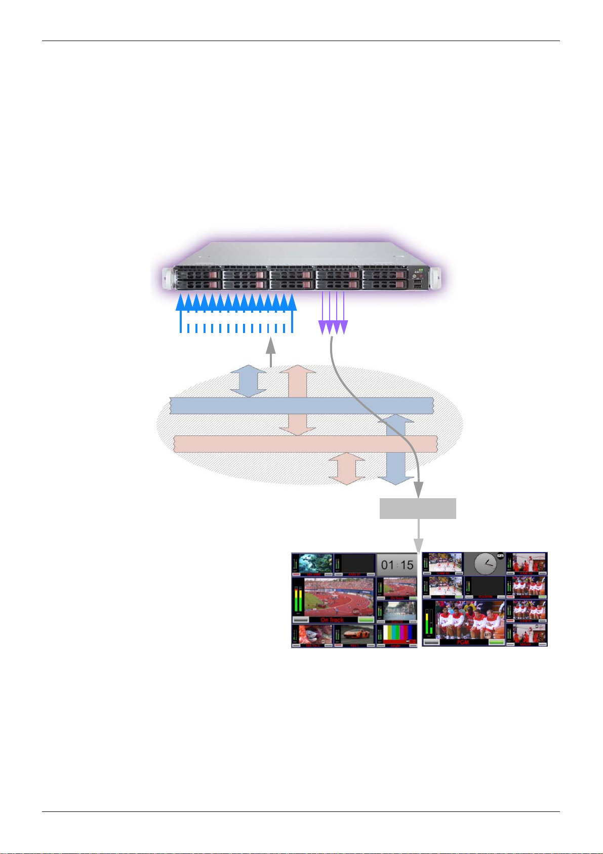
3.3.2 Turnkey MV-805 Hardware-Optimized Software
Inside a turnkey MV-805, a hardware-optimized SAM IP multiviewer software application
implements the MV-805’s “multiviewer functionality”. This uses the media IP network
interface(s) for all media IP streams (In and Out) and it uses further network port(s) for
connection to a control IP network for control/servicing.
IP streams (in or out) connect to ‘spigots’ on the IP multiviewer software application.
Each video input IP stream is taken from the media IP network interface by the software
application. The final multiviewer display output image is formed and provided as a video IP
stream to the media IP network interface.
Figure 3 shows the connection of the MV-805’s multiviewer software application to the unit’s
external interfaces.
Destination Spigots:
Each input spigot of the IP multiviewer software application looks for a specific multicast IP
stream from the media IP network interface(s) and takes those multicast data packets. Thus,
all multiviewer video inputs are acquired by each spigot.
Source Spigots:
Each output spigot packetizes all or part of a multiviewer display output image and sources a
multicast IP stream containing a video wall. This is sent out via the media IP network
interface(s).
Figure 3 Internal Connections to the Hardware-Optimized IP Multiviewer Software Application
Spigots
Note:
MV-805-16 has two media network interfaces, 1A and 1B.
MV-805-32 has four media network interfaces, 1A,1B, 2A and 2B.
(i.e. the MV-805-32 has twice the network interface bandwidth.)
External
Interfaces
See Note.

MV-805 IP Multiviewer User Manual Functionality Architecture and Signal Flow Product Overview 3.3
Issue1 Revision 1 Page 17 © 2018 SAM
3.3.3 Network Redundancy
The MV-805 offers support for network redundancy, ensuring protection of an IP pathway
from a multicast IP stream’s source to the MV-805’s destination spigot via second network
(Fabric B), see Figure 4. Thus there are two identical Multicast IP streams available.
The receiving destination spigots use both IP streams to re-form the original IP stream, using
the first data packet to arrive from fabrics “A” or “B”.
3.3.4 IP Streams and Flows
IP streams are IGMPv3 multicast IP streams.
IP streams may consist of sub-streams, or “flows” (see Figure 5). There are three media IP
flows:
• Video flow - carries video image essence.
• Audio flow - carries audio essence.
• Metadata flow.
Figure 4 IP Fabrics “A” and “B” providing Redundant IP Streams
Figure 5 IP Flows comprising a Video IP Stream

MV-805 IP Multiviewer User Manual Input Video Signal Selection Product Overview 3.4
Issue1 Revision 1 Page 18 © 2018 SAM
3.4 Input Video Signal Selection
Generally, steps for the selection of a multiviewer input video signal:
Step 1. Send control messages to the MV-805 unit to cause an MV-805 destination spigot
to look out for data packets belonging to a new multicast IP stream.
Step 2. Route the new multicast IP stream data packets to the MV-805 unit.
Typically, the MV-805 is connected to a SAM video IP routing system where Steps 1 and 2
are done by the routing system; the switching over from one IP stream to another is done at
the multiviewer input itself, at its destination spigot.
Switching type at MV-805 inputs is ‘break-before-make’.
3.4.1 MV-805 and SAM IP Routing System
In a SAM IP routing system, Steps 1 and 2above are carried out automatically.
The routing of the new multicast IP stream to the MV-805 unit (i.e. step 2 above) is done
automatically in the SAM IP routing system. The MV-805 unit then receives the necessary
multicast IP stream and the corresponding destination spigot can then gather its new
multicast data packets.
Note:
SAM IP Routing System - IP Routing System Controller (IP-RSC) Unit:
SAM offer an IP Routing Solution which controls and presents an IP routing system like a
traditional video router. This is done via one IP Routing System Controller unit (two units if
controller redundancy is required).
SAM’s IP Routing System Controller unit can represent an IP routing system as a
traditional video router, with simple port names and numbers for source and destination
ports. Video routing control is then done from traditional video router hard/soft control
panels and interfaces etc.
SAM’s IP Routing System Controller unit contains two functional blocks:
•IPRC: IP Router Controller - This block connects to the external traditional video
router hard/soft control panels and interfaces.
•IPRA: IP Routing Adapter - This block connects to the IP routing devices.
Note:
SAM Orbit Software Tool:
SAM’s Orbit software tool is used to prepare and configure an IP routing system for:
• Real-time video routing operation.
• Operation with a SAM IP Routing System Controller (IP-RSC) unit.
IP-RSC IPRC
IPRA
Traditional Video Router Control
IP Routing System

MV-805 IP Multiviewer User Manual Input Video Signal Selection Product Overview 3.4
Issue1 Revision 1 Page 19 © 2018 SAM
3.4.2 Non-SAM IP Routing
For non-SAM IP routing systems, a SAM IQTIC modular card is required by the MV-805 to
translate SAM protocols into an external third-party control, SDC-01.
The user must:
1. Carry out destination spigot changes (step 1 above).
2. Route multicast streams as required (step 2 above).

MV-805 IP Multiviewer User Manual Network Topologies Product Overview 3.5
Issue1 Revision 1 Page 20 © 2018 SAM
3.5 Network Topologies
The 1RU turnkey MV-805 uses out-of-band control. Network topologies suitable for MV-805
include those described in Figure 6 to Figure 8.
Figure 6 Network Topology - One Media IP Fabric, One Control Network.
Figure 7 Network Topology - Two Media IP Fabrics (A and B), One Control Network.
Table of contents


