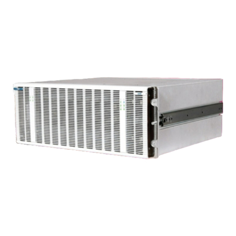
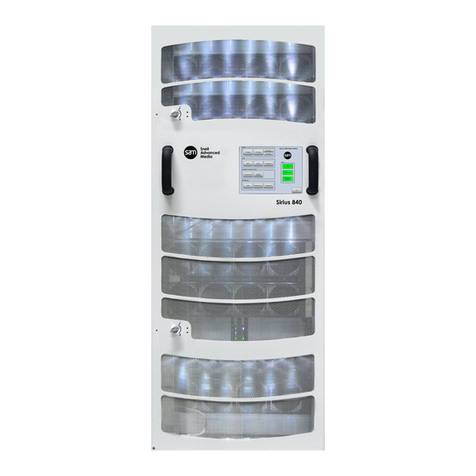
Snell Sirius 600 User manual

snellgroup.com
User Manual
Sirius 600
Medium-scale router offering a mix of AES, SDI, ASI and HD and 3G
signals in one frame

Sirius 600 www.snellgroup.com Contents
Issue 1 Rev 3 Page 2 © 2014 Snell Limited
Contents
1. Introduction. . . . . . . . . . . . . . . . . . . . . . . . . . . . . . . . . . . . . . . . . . . . . . . . . . . . . . . . . 4
1.1 Design Features . . . . . . . . . . . . . . . . . . . . . . . . . . . . . . . . . . . . . . . . . . . . . . . . . . 4
1.2 Sirius 600 User Manuals. . . . . . . . . . . . . . . . . . . . . . . . . . . . . . . . . . . . . . . . . . . . 5
2. Quick Start Guide. . . . . . . . . . . . . . . . . . . . . . . . . . . . . . . . . . . . . . . . . . . . . . . . . . . . 6
2.1 Router Configuration. . . . . . . . . . . . . . . . . . . . . . . . . . . . . . . . . . . . . . . . . . . . . . . 6
2.2 Sirius 600 Control . . . . . . . . . . . . . . . . . . . . . . . . . . . . . . . . . . . . . . . . . . . . . . . . . 7
2.2.1 Master Sirius 600 Frames Only . . . . . . . . . . . . . . . . . . . . . . . . . . . . . . . . 7
2.2.2 Slave Sirius 600 Frames Only . . . . . . . . . . . . . . . . . . . . . . . . . . . . . . . . . 7
3. Installation . . . . . . . . . . . . . . . . . . . . . . . . . . . . . . . . . . . . . . . . . . . . . . . . . . . . . . . . . 8
3.1 System Components. . . . . . . . . . . . . . . . . . . . . . . . . . . . . . . . . . . . . . . . . . . . . . . 8
3.2 Sirius 600 Cards 1 & 2 Compatibility. . . . . . . . . . . . . . . . . . . . . . . . . . . . . . . . . . . 8
3.2.1 Sirius 600 Compatibility Rules . . . . . . . . . . . . . . . . . . . . . . . . . . . . . . . . .11
3.3 Card locations in Sirius 620 (7U) Frame. . . . . . . . . . . . . . . . . . . . . . . . . . . . . . . 13
3.4 Card Location in a Sirius 610 (4U) Frame - Video and Audio Combinations . . . 14
3.5 Sirius 610 (4U) Frame Options . . . . . . . . . . . . . . . . . . . . . . . . . . . . . . . . . . . . . . 15
3.6 Card Locations in Sirius 610 (4U) Frame - Audio Only. . . . . . . . . . . . . . . . . . . . 15
3.7 Card Locations in Sirius 630 (16U) Video or Unbalanced AES Router Frame . . 16
3.8 SDV Router Configurations. . . . . . . . . . . . . . . . . . . . . . . . . . . . . . . . . . . . . . . . . 18
3.9 AES Router Configurations. . . . . . . . . . . . . . . . . . . . . . . . . . . . . . . . . . . . . . . . . 18
3.10 Inserting and Removing Cards . . . . . . . . . . . . . . . . . . . . . . . . . . . . . . . . . . . . . 20
3.11 Ventilation . . . . . . . . . . . . . . . . . . . . . . . . . . . . . . . . . . . . . . . . . . . . . . . . . . . . . 20
3.12 Fan Module . . . . . . . . . . . . . . . . . . . . . . . . . . . . . . . . . . . . . . . . . . . . . . . . . . . . 21
3.13 Power Supplies . . . . . . . . . . . . . . . . . . . . . . . . . . . . . . . . . . . . . . . . . . . . . . . . . 21
3.14 Rear Panel Control Connections and Switches . . . . . . . . . . . . . . . . . . . . . . . . 22
3.15 Control Connector Pinouts . . . . . . . . . . . . . . . . . . . . . . . . . . . . . . . . . . . . . . . . 25
3.15.1 'EXP' Connector Pinout . . . . . . . . . . . . . . . . . . . . . . . . . . . . . . . . . . . . 25
3.15.2 'RS485-1 and 2' Connector Pinouts. . . . . . . . . . . . . . . . . . . . . . . . . . . 26
3.15.3 'Config A and B' RS232 Connector Pinouts. . . . . . . . . . . . . . . . . . . . . 26
3.15.4 RS485 Port 3 Pinout . . . . . . . . . . . . . . . . . . . . . . . . . . . . . . . . . . . . . . 27
3.15.5 Alarms Pinouts. . . . . . . . . . . . . . . . . . . . . . . . . . . . . . . . . . . . . . . . . . . 27
3.15.6 Balanced AES Reference Pinout. . . . . . . . . . . . . . . . . . . . . . . . . . . . . 28
3.16 Using the AES Reference . . . . . . . . . . . . . . . . . . . . . . . . . . . . . . . . . . . . . . . . . 29
3.17 Using the Video Reference . . . . . . . . . . . . . . . . . . . . . . . . . . . . . . . . . . . . . . . . 29
4. Sirius Gold . . . . . . . . . . . . . . . . . . . . . . . . . . . . . . . . . . . . . . . . . . . . . . . . . . . . . . . . 30
4.1 Ventilation . . . . . . . . . . . . . . . . . . . . . . . . . . . . . . . . . . . . . . . . . . . . . . . . . . . . . . 30
4.2 Frame Layout . . . . . . . . . . . . . . . . . . . . . . . . . . . . . . . . . . . . . . . . . . . . . . . . . . . 32
4.2.1 Front Layout. . . . . . . . . . . . . . . . . . . . . . . . . . . . . . . . . . . . . . . . . . . . . . 32
4.2.2 Inserting and Removing Cards. . . . . . . . . . . . . . . . . . . . . . . . . . . . . . . . 33
4.2.3 Rear Layout . . . . . . . . . . . . . . . . . . . . . . . . . . . . . . . . . . . . . . . . . . . . . . 33
4.3 Sirius Gold Cards . . . . . . . . . . . . . . . . . . . . . . . . . . . . . . . . . . . . . . . . . . . . . . . . 34
4.3.1 Sirius Gold Crosspoint Cards. . . . . . . . . . . . . . . . . . . . . . . . . . . . . . . . . 34
4.3.2 Sirius Gold Fan Monitoring and Reference Card (2428) . . . . . . . . . . . . 35
4.3.3 Sirius Gold Monitoring Card (2429) . . . . . . . . . . . . . . . . . . . . . . . . . . . . 38
4.4 Monitoring Architecture . . . . . . . . . . . . . . . . . . . . . . . . . . . . . . . . . . . . . . . . . . . . 38
4.4.1 Sirius Gold Monitoring Card (2429) . . . . . . . . . . . . . . . . . . . . . . . . . . . . 38
4.5 Sirius Gold Rear Connectors. . . . . . . . . . . . . . . . . . . . . . . . . . . . . . . . . . . . . . . . 40
4.5.1 Sirius Gold Inputs and Outputs . . . . . . . . . . . . . . . . . . . . . . . . . . . . . . . 40
4.6 Connecting Your Router . . . . . . . . . . . . . . . . . . . . . . . . . . . . . . . . . . . . . . . . . . . 43
4.6.1 Controlling Your Router . . . . . . . . . . . . . . . . . . . . . . . . . . . . . . . . . . . . . 43
4.6.2 Configuration . . . . . . . . . . . . . . . . . . . . . . . . . . . . . . . . . . . . . . . . . . . . . 43
4.7 Power Supplies . . . . . . . . . . . . . . . . . . . . . . . . . . . . . . . . . . . . . . . . . . . . . . . . . . 43
4.7.1 Releasing the door. . . . . . . . . . . . . . . . . . . . . . . . . . . . . . . . . . . . . . . . . 44
4.7.2 Fitting the Door. . . . . . . . . . . . . . . . . . . . . . . . . . . . . . . . . . . . . . . . . . . . 44
4.7.3 Power Supplies . . . . . . . . . . . . . . . . . . . . . . . . . . . . . . . . . . . . . . . . . . . 44
4.7.4 Removing a Power Supply Unit (PSU). . . . . . . . . . . . . . . . . . . . . . . . . . 45

Sirius 600 www.snellgroup.com Contents
Issue 1 Rev 3 Page 3 © 2014 Snell Limited
4.7.5 Fitting a Replacement Power Supply. . . . . . . . . . . . . . . . . . . . . . . . . . . 45
4.8 Specification . . . . . . . . . . . . . . . . . . . . . . . . . . . . . . . . . . . . . . . . . . . . . . . . . . . . 45
5. The Nebula Control System. . . . . . . . . . . . . . . . . . . . . . . . . . . . . . . . . . . . . . . . . . . 47
5.1 Controlling Sirius. . . . . . . . . . . . . . . . . . . . . . . . . . . . . . . . . . . . . . . . . . . . . . . . . 47
5.2 Control Module Functions . . . . . . . . . . . . . . . . . . . . . . . . . . . . . . . . . . . . . . . . . . 47
5.3 An Example Multi-level System. . . . . . . . . . . . . . . . . . . . . . . . . . . . . . . . . . . . . . 48
5.4 Control Module and Editor Versions . . . . . . . . . . . . . . . . . . . . . . . . . . . . . . . . . . 48
5.4.1 2430 Control Module . . . . . . . . . . . . . . . . . . . . . . . . . . . . . . . . . . . . . . . 49
5.4.2 2431 Interface Module . . . . . . . . . . . . . . . . . . . . . . . . . . . . . . . . . . . . . . 49
5.4.3 2432 Control Module . . . . . . . . . . . . . . . . . . . . . . . . . . . . . . . . . . . . . . . 49
5.4.4 2433 Interface Module . . . . . . . . . . . . . . . . . . . . . . . . . . . . . . . . . . . . . . 49
5.4.5 2434 and 2435 . . . . . . . . . . . . . . . . . . . . . . . . . . . . . . . . . . . . . . . . . . . . 49
5.4.6 Snell Router Editor. . . . . . . . . . . . . . . . . . . . . . . . . . . . . . . . . . . . . . . . . 49
5.4.7 Nebula Editor . . . . . . . . . . . . . . . . . . . . . . . . . . . . . . . . . . . . . . . . . . . . . 49
5.5 Dual Redundant Controller Operation. . . . . . . . . . . . . . . . . . . . . . . . . . . . . . . . . 50
5.6 System Diagram . . . . . . . . . . . . . . . . . . . . . . . . . . . . . . . . . . . . . . . . . . . . . . . . . 51
6. Configuring the Control Module . . . . . . . . . . . . . . . . . . . . . . . . . . . . . . . . . . . . . . . 52
6.1 Choosing a Fixed or Editable Database . . . . . . . . . . . . . . . . . . . . . . . . . . . . . . . 52
6.2 The Sirius 600 Control and Interface Modules . . . . . . . . . . . . . . . . . . . . . . . . . . 52
6.2.1 2430/2/4 Control Modules . . . . . . . . . . . . . . . . . . . . . . . . . . . . . . . . . . . 52
6.2.2 2431/3/5 Interface Modules . . . . . . . . . . . . . . . . . . . . . . . . . . . . . . . . . . 52
6.3 2441/3/5 Configuration Switches. . . . . . . . . . . . . . . . . . . . . . . . . . . . . . . . . . . . . 53
6.3.1 Switch Descriptions . . . . . . . . . . . . . . . . . . . . . . . . . . . . . . . . . . . . . . . . 53
6.4 2441/3/5 Diagnostic LEDS . . . . . . . . . . . . . . . . . . . . . . . . . . . . . . . . . . . . . . . . . 54
6.5 Reset Buttons . . . . . . . . . . . . . . . . . . . . . . . . . . . . . . . . . . . . . . . . . . . . . . . . . . . 54
6.6 Control Port Details. . . . . . . . . . . . . . . . . . . . . . . . . . . . . . . . . . . . . . . . . . . . . . . 55
6.7 Control Protocol Descriptions . . . . . . . . . . . . . . . . . . . . . . . . . . . . . . . . . . . . . . . 55
6.7.1 Snell General Switcher Protocol (SW-P-02) . . . . . . . . . . . . . . . . . . . . . 55
6.7.2 Snell Multi-Drop Communications Protocol (SW-P-06) . . . . . . . . . . . . . 56
6.7.3 Snell Simple Switcher Protocol (SW-P-03) . . . . . . . . . . . . . . . . . . . . . . 56
6.8 2430/2432/2434 Configuration Switches. . . . . . . . . . . . . . . . . . . . . . . . . . . . . . . 57
6.8.1 Setting the 4-way DIP switches . . . . . . . . . . . . . . . . . . . . . . . . . . . . . . . 57
6.8.2 Selecting Serial RS485-2, RS485-3, or Ethernet Control . . . . . . . . . . . 59
6.8.3 Level Mapping in a Sirius 630 (16U) . . . . . . . . . . . . . . . . . . . . . . . . . . . 60
6.8.4 Level Mapping in a Sirius 620 (7U) . . . . . . . . . . . . . . . . . . . . . . . . . . . . 60
6.8.5 Level Mapping in a Sirius 610 (4U) . . . . . . . . . . . . . . . . . . . . . . . . . . . . 60
6.8.6 Examples of Non-square Configurations . . . . . . . . . . . . . . . . . . . . . . . . 61
7. Using the Ethernet Port . . . . . . . . . . . . . . . . . . . . . . . . . . . . . . . . . . . . . . . . . . . . . . 63
7.1 Connecting Sirius 600 to a Network . . . . . . . . . . . . . . . . . . . . . . . . . . . . . . . . . . 63
7.2 Configuration Tool . . . . . . . . . . . . . . . . . . . . . . . . . . . . . . . . . . . . . . . . . . . . . . . . 63
8. Troubleshooting. . . . . . . . . . . . . . . . . . . . . . . . . . . . . . . . . . . . . . . . . . . . . . . . . . . . 64
9. Specification. . . . . . . . . . . . . . . . . . . . . . . . . . . . . . . . . . . . . . . . . . . . . . . . . . . . . . . 67
9.1 General . . . . . . . . . . . . . . . . . . . . . . . . . . . . . . . . . . . . . . . . . . . . . . . . . . . . . . . . 67
9.1.1 Control . . . . . . . . . . . . . . . . . . . . . . . . . . . . . . . . . . . . . . . . . . . . . . . . . . 67
9.1.2 Reference. . . . . . . . . . . . . . . . . . . . . . . . . . . . . . . . . . . . . . . . . . . . . . . . 67
9.1.3 Power Supplies . . . . . . . . . . . . . . . . . . . . . . . . . . . . . . . . . . . . . . . . . . . 67
9.1.4 General . . . . . . . . . . . . . . . . . . . . . . . . . . . . . . . . . . . . . . . . . . . . . . . . . 67
9.1.5 Temperature Range . . . . . . . . . . . . . . . . . . . . . . . . . . . . . . . . . . . . . . . . 67

Sirius 600 www.snellgroup.com Introduction
Issue 1 Rev 3 Page 4 © 2014 Snell Limited
1. Introduction
The Sirius 600 range consists of four self-contained, multi-format, multi-level signal routers
with a maximum size of 512 x 512. The use of a generic broadband crosspoint has given the
Sirius 600 range the ability to pass any digital signal type, up to and including 3D-SDI,
through the same crosspoint matrix. Input and output processing is performed by modular,
signal specific, Input/Output cards. Standard input and output cards have eight signal paths,
and are available in SD-SDI, HD-SDI and 3G-SDI and AES audio formats. The system is
further enhanced by the addition of video and audio ADC and DAC cards, enabling full
analogue/digital conversion as required.
The Sirius 600 range includes four sizes of chassis, each offering specific maximum router
configurations, but using the same input and output cards, and thereby offering efficient and
cost effective upgrade paths. The Sirius 600 range may be summarized as follows:
• Sirius Gold (39U): Maximum of 512 x 512 (up to HD-SDI rates)
• Sirius 630 (16U): maximum 256x256 using four 256x64 crosspoint cards
• Sirius 620 (7U): maximum 128x128 using four 128x32 crosspoint cards
• Sirius 610 (4U): maximum 64x64 using two 128x32 crosspoint cards
The Sirius 610 (4U) frame can offer:
• between 128x1 and 64x64 (increments of 8) routing, all signal types
The Sirius 600 series design philosophy provides a solution for systems undergoing an
analogue to digital, or SDV to HDTV transition, and provides the platform for an array of
modular enhancements and options. The Sirius 600 product range includes:
• SDV crosspoint modules, for cost effective routing up to 360Mb/s
• HDTV crosspoint modules, for routing all digital signals up to 3 Gb/s
Sirius 600 series uses the Snell Nebula control system, common to many Snell routers,
allowing the direct connection of up to 32 control panels or Under Monitor Displays to the
chassis. The user may select a pre-configured database to get the system up and running, or
use a Windows based editor to customize the router to their own specific requirements.
Nebula also allows the configuration of crosspoint salvoes, route protects and inhibits,
multi-level operation and connection to Snell's Aurora router controller. The Sirius 600 chassis
may control other Sirius 600, Freeway or Halo routers as slave systems using a control bus
expansion connection, although an existing Freeway cannot control any Sirius 600 router.
Sirius 600 has been designed with true input and output monitoring available as an option.
Additional modules have analogue and digital, video and audio outputs, such that any input or
output may be accessed, on both video and audio levels within a single frame.
1.1 Design Features
Sirius 600, despite it's innovative design, has many of the features associated with Snell's
hardware products, giving it a robustness and ease of maintenance essential in critical signal
applications. All modules are 'hot-pluggable'; surge suppression circuitry, and phased
power-up allow quick and safe module swapping, this is further aided by the retention of
crosspoint and configuration data in non-volatile control card memory. All modules are
addressed by their position in the frame, rather than by jumper settings, and the careful
consideration of power routing and driver voltage levels ensures that mis-plugged modules
are not damaged.
If dual control cards are fitted; crosspoint, configuration and database information is
synchronized between the two cards. Changeover is automatic in the event of failure, and the
tri-state buffering of all control signals ensures that changeover is also transparent to both the
internal and any external systems.

Sirius 600 www.snellgroup.com Introduction
Issue 1 Rev 3 Page 5 © 2014 Snell Limited
All the frames are non-expandable, therefore there is no requirement for signals to be bussed
or 'rippled' through crosspoint cards, all signals are routed point to point, using discrete
buffering, thereby maintaining signal integrity and quality. This approach also allows the
router to be part equipped or 'partitioned' with no loss of functionality. A further advantage of
maintaining a short, quality, signal path is that the re-clocking of digital signals on the output
stage, usually a necessity on traditional routers, is no longer an essential requirement.
Because some of the digital signal types currently used do not necessarily benefit from
re-clocking, a full specification, non-re-clocking router is a distinct advantage. This allows the
user to opt for non-re-clocking outputs without degrading the system specification, and at the
same time providing a cost-effective and signal-independent solution.
The Sirius 600 video router operates in a mixed standard environment, providing both 525
and 625 line references are supplied to the frame, ensuring SMPTE RP168 compliant
switching between sources of the same standards. The Sirius 600 audio router is designed to
work with mixed stereo and mono channels, where the necessary combining and switching is
applied at both the input and output stages, for both the analogue and digital formats. The
audio signal mode of each channel may either be stored in the database, or configured
dynamically from a standard master control panel.
The dual redundant power supply units only supply 48 volts, all modules convert this to the
required levels locally, which not only makes the power routing simple, but provides thorough
power rail de-coupling between modules.
1.2 Sirius 600 User Manuals
Sirius 600 is a modular product with an unknown number of permutations of router
configuration, a single user manual for all users is not possible. What each user will receive is
a core manual, giving general information for the Sirius 600 frames, control card configuration
details and database information. They will also be supplied with supplement user manuals
describing each crosspoint, input and output module currently available. Finally, the Nebula
User Guide will also be supplied, along with the database editor software, allowing the user to
configure the system to their own requirements. Module upgrades and additions will only
affect the appropriate supplements, and simplify the documentation process.
General information on Snell products is now contained in a separate user manual, detailing
warranty, customer support and EMC compliance data.
In summary, the following user manuals are available:
• Sirius 600 user guide: Sirius Gold (39U), Sirius 630 (16U), Sirius 620 (7U), Sirius 610
(4U), control module and database
• Nebula User Guide
• Sirius 600 Crosspoint Cards
• 3G Crosspoint Cards
• Sirius 600 SDI Input/Output cards
• Sirius 600 Audio Converters
• Sirius 600 AES Input/Output cards
• Sirius 600 Video Converters
• Sirius 600 Monitoring
• Sirius 600 HD Input/Output cards
• Sirius 600 3G Input/Output Cards
• General Information for Snell products

Sirius 600 www.snellgroup.com Quick Start Guide
Issue 1 Rev 3 Page 6 © 2014 Snell Limited
2. Quick Start Guide
2.1 Router Configuration
Fig 1. Router Configuration
Do you have a 16U,
7U or 4U frame?
Does the router have
4999 modules fitted?
Does the frame have a
2430 /2/4 or 2431/3/5
control module (s)?
With the front door removed ,
compare the modules in your
system with the diagrams in
Section 3.3 and 3.7 and the
module list in Section 3.1
You have a balanced
AES router, compare it
with the diagram in
Section 3.6 to
determine the size .
Compare your frame
with the diagram in
Section 3.4, and the
list in Section3.1 to
determine the size.
You have a Master
Sirius frame, which can
run as a stand-alone,
and can also control
other 'slave' frames ,
see Section 5
You have a Slave
Sirius frame, which
must connect to a
Master Sirius frame,
see Section 5
Determine how many levels
of what size you require by
setting the switches on the
front of the 2430/1/2/3/4/5
module using the diagram in
Section 6.7
No
Yes
2430 /2/4 2431/3/5
Sirius 630 (16U) or
Sirius 620 (7U) Sirius 610 (4U)

Sirius 600 www.snellgroup.com Quick Start Guide
Issue 1 Rev 3 Page 7 © 2014 Snell Limited
2.2 Sirius 600 Control
2.2.1 Master Sirius 600 Frames Only
2.2.2 Slave Sirius 600 Frames Only
Fig 2. Router Configuration
Will you run the Sirius
standalone, or connect it
to another control system,
like Aurora?
Will it use the 'fixed'
database, see the Nebula
guide, or a user specified
editable database ?
Do your system
dimensions lie within those
specified by the 'fixed'
database settings (see
Nebula guide )?
Set the 2441/3/5 switches
for fixed database and the
ports for 'panel' mode, see
Section 6.2. Connect the
control panels to the
RS485 ports with the
appropriate address
setting, see the Nebula
guide.
Set the 2441/3/5 switches
for fixed database and
remote control, see
Section 5.3, and connect
either of the RS485 ports
to Aurora. Configure the
Aurora database to match
your system's physical
configuration.
Create a database
using the editor, see
the Nebula guide . Set
the 2441/3/5 switches
for 'editable database ',
see Section 6.2, Load
the database into the
frame.
Standalone Aurora
Fixed Editable No Yes
Fig 3. Router Configuration
Using a control bus expansion cable , connect
the frame to a Master frame . Check the slave
configuration by referring to the 2431/3/5
switches, see Section 6.7. Configure the
master system as above.

Sirius 600 www.snellgroup.com Installation
Issue 1 Rev 3 Page 8 © 2014 Snell Limited
3. Installation
The Sirius 600 range of routers is supplied in 16U, 7U or 4U frames with integral power
supplies and cooling. All cards and modules are accessible from the front after the door has
been opened or removed, and all signal and control cables are connected to rear panels.
Ventilation air is taken from the left hand side of the frame, and exhausted on the right hand
side, and this must be considered when mounting the unit (see Section 3.12).
If you experience any difficulties with any Sirius 600 frame, please refer first to Section 8 -
Trouble Shooting, and then if you are still having difficulties contact customer support as
detailed in the General Information user manual.
3.1 System Components
The following table identifies all major Sirius 600 components; all modules are marked with a
four-digit part number. Use this table to check the compatibility of module types in your
system:
3.2 Sirius 600 Cards 1 & 2 Compatibility
Snell's Sirius 600 Router range contains both established and current products. The range
can be classified as Series 1 and Series 2.
Table 1. identifies whether the card is a series 1 or series 2 card and gives an indication on
compatibility. Please read section 3.2.1.1 The table is correct at time of printing; if you are in
any doubt please consult your Snell representative.
Note:
It is important NOT to mix certain Series 1 cards with Series 2 cards.
Snell Sirius 600 Card Description Card
Module Rear
Connector
SERIES I cards (Can be mixed with Series 2 xpoint card)
SDV Output, Non-Re-clocking 3996 1764
SDV Output Re-clocking 3995 1764
SERIES I cards (Cannot be mixed with Series 2 xpoint card)
AES Input, Asynchronous (Crash), Balanced 4992 1763
AES Output, Asynchronous (Crash), Balanced 4996 1766
AES Input, Synchronous (clean), Balanced 4993 1763
SERIES I cards (Cannot be mixed with Series 2 xpoint card)
AA Input, Balanced 4790 1767
AA output Balanced 4795 1768
SERIES 2 cards (Can be mixed with Series I xpoint card)
SDV Input 3994 1762
SDV Output, Non-Re-clocking 3999 1774
SDV Output Re-clocking 3998 1774
SERIES 2 cards
HD Input 3992 3993
HD Output 3997 1774
Table 1. Sirius 600 Cards 1 & 2 Compatibility

Sirius 600 www.snellgroup.com Installation
Issue 1 Rev 3 Page 9 © 2014 Snell Limited
Table 2. is a comprehensive list of Snell Sirius 600 Cards and Modules. The list contains both
legacy and current product. Please check availability.
3G cards
3G Re-clocking Input 3972 3973 Coax
3971 Fibre
3G Re-clocking Output 3978 1774
3G Re-clocking Output 3965 3966
3G/HD/SD Re-clocking Fibre Output 3976 3974
SERIES 2 cards (Can be mixed with Series I xpoint card)
AES Input, Asynchronous (Crash), Balanced 4992 1763
AES Output, Asynchronous (Crash), Balanced 4996 1766
AES Input, Synchronous (Clean), Balanced 4993 1763
AES Output, Synchronous (Clean), Balanced 4997 1766
SERIES 2 cards
AV Input 3790 1762
AV Output 3795 1764
SERIES 2 cards (Can be mixed with Series I xpoint card)
AA Input, Balanced 4791 1767
AA Output, Balanced 4796 1768
Series Card Description
Sirius 600 1 Input/Output Cards
1 3995 SDV Re-clocking Output
1 3996 SDV Non-Re-clocking
1 1764 Rear panel for SDV 3995/6 and analogue Video o/p
1 4992 AES Asynchronous Input
1 4993 AES Synchronous Input
1 4996 AES Synchronous or Asynchronous Output
1 4999 AES In/Out Sirius 610 (4U) frame with 4911 Crosspoints
1 4790 Stereo Analogue Audio I/P
1 4795 Stereo Analogue Audio O/P
Sirius 600 1 Input/Output Cards –Timecode & Data
1 4793 Balanced Timecode Input
1 4797 Balanced Timecode Output
1 4794 Balanced Data Input
1 4798 Balanced Data Output
Sirius 600 1 and 2 Audio Rear Panels
1 / 2 1763 AES 16 Channel Input Balanced
1 / 2 1770 AES 16 Channel Input Balanced
1 / 2 1762 AES 8 Channel I/P Unbalanced
1 / 2 1766 AES 16 Channel Output Balanced Sirius 610 (4U), Sirius 620
(7U), Sirius 630 (16U)
1 / 2 1771 AES 16 Channel Output Balanced Sirius 620 (7U) only
Table 2. Snell Sirius 600 Cards and Modules
Snell Sirius 600 Card Description Card
Module Rear
Connector
Table 1. Sirius 600 Cards 1 & 2 Compatibility (Continued)

Sirius 600 www.snellgroup.com Installation
Issue 1 Rev 3 Page 10 © 2014 Snell Limited
1 / 2 1764 AES 8 Channel Output Unbalanced
1 / 2 1767 Analogue Audio Input
1 / 2 1768 Analogue Audio Output
Sirius 600 1 Crosspoints
Legacy product – Check availability
13906
128x32 HD/SDV/Audio Crosspoint Sirius 610 (4U)/Sirius 620 (7U)
Legacy product – check availability
14909
256x64 Audio Crosspoint Audio/AES/Data/Timecode
Legacy product – check availability
13909
256x64 SDV/Audio Crosspoint Sirius 630 (16U)
Legacy product – check availability
13907
128x32 SDV/Audio Crosspoint Sirius 610 (4U)/Sirius 620 (7U)
Legacy product – check availability
14911
128x32 in Sirius 610 (4U)/Sirius 620 (7U) frame with 4992/1/5
modules
128x64 Audio Sirius 610 (4U) with 4999 modules
Crosspoint
Legacy product – check availability
Sirius 600 2 Input/Output Cards
2 3994 SDV Input
2 3998 SDV Re-clocking Output module
2 3999 SDV Non-Re-clocking Output module
2 3790 Composite Video Input
2 3795 Composite Video Output module
2 1762 SDV & Analogue Video Input module
2 1774 HD & Sirius 600 2 SD Outputs
21764
SDV rear panel for SDV 3995/6 and Analogue Video Output
modules.
2 3972 3G Re-clocking Input
2 3973 3G Input rear (use with 3972 for co-ax)
2 3971 3G Input rear (use with 3972 for fibre)
2 3993 HD Input BNC module
2 3992 HD Input module
2 3991 HD Re-clocking Input
2 3997 HD Re-clocking Output
2 3978 3G Re-clocking Output (uses 1774 rear)
2 1774 3G/HD & Sirius 600 2 SD Outputs
2 3965 3G Re-clocking Output (uses 3966 rear)
2 3966 3G Re-clocking Output rear
2 3991 HD Re-clocking Input module
2 3970 HD/SD Fibre Input
Series Card Description
Table 2. Snell Sirius 600 Cards and Modules (Continued)

Sirius 600 www.snellgroup.com Installation
Issue 1 Rev 3 Page 11 © 2014 Snell Limited
3.2.1 Sirius 600 Compatibility Rules
Do not use Sirius 600 1 Audio modules, Timecode or data in a frame with any Sirius 600 2
cards or Sirius 600 1 4911's (Sirius 610 (4U)/Sirius 620 (7U)) or 4909's (Sirius 630 (16U)) i.e.
Sirius 600 1 Audio 4790's & 4992/4993's: DO NOT USE with all Sirius 600 2 crosspoint cards.
Can only be used with Sirius 600 1 crosspoint cards except the 4911's (Sirius 610 (4U)/Sirius
620 (7U)) or 4909's (Sirius 630 (16U)).
The following cards are derived from the Sirius 600 1 4992/1 and hence also can only be
used with Sirius 600 1 Crosspoint cards 4911/9's except the 4911's (Sirius 610 (4U)/Sirius
620 (7U)) or 4909's (Sirius 630 (16U)):
• 4999's (Sirius 600 1) AES Input/Output combined.
2 3976 3G/HD/SD Re-clocking Fibre Output (uses 3974 rear)
2 3974 3G Fibre Output rear
2 3975 HD/SD Fibre Output 1310nm
2 3977 HD/SD Fibre Output 1550nm
2 4992 AES Asynchronous switching Input
2 4993 AES Synchronous switching Input
2 4996 AES Asynchronous switching Output
2 4997 AES Synchronous switching Output
2 4791 Stereo Analogue Audio Input
2 4796 Stereo Analogue Audio Output
24998
AES Input/Output Card for Sirius 610 (4U) frame with Audio
crosspoint
Should not be mixed with other input or output card types
Sirius 600 2 Input/Output Cards Timecode & Data
2 4792 Timecode Balanced Input module
2 4799 Timecode Balanced Output module
2 4788 Data Balanced Input module
2 4789 Data Balanced Output
Sirius 600 2 Crosspoint Options
24993
128x32 / 128x64 Audio Crosspoint Module for Sirius 610 (4U) and
Sirius 620 (7U) frames. Operates as 128x32 in Sirius 620 (7U)
frames and Sirius 610 (4U) frames with 4992/4993/4996/4997
modules, and as 128x64 in Sirius 610 (4U) with 4998 modules.
23912
128x32 HD/SD/Audio Crosspoint Module for Sirius 610 (4U) and
Sirius 620 (7U) frames
23962
128x32 3GHD/SD/Audio Crosspoint Module for Sirius 610 (4U)
and Sirius 620 (7U) frames
24908
256x64 Audio Crosspoint Module. Routes Audio / AES, data and
timecode.
23908
256x64 HD/SD/Audio Crosspoint Module for Sirius 630 (16U)
Frame.
23969
256x64 3GHD/SD/Audio Crosspoint Module for Sirius 630 (16U)
Frame.
23913
Sirius 600 Gold 256x64 HD / SD / Audio Crosspoint Module.
Routes signals from 2MBit/s to 1.5GBit/s
Series Card Description
Table 2. Snell Sirius 600 Cards and Modules (Continued)

Sirius 600 www.snellgroup.com Installation
Issue 1 Rev 3 Page 12 © 2014 Snell Limited
• 4793 Sirius 600 1 Timecode I/P
• 4794 Sirius 600 1 Data I/P.
DO NOT USE with all Sirius 600 2 crosspoint cards.
Always use the correct rear panels. i.e Sirius 600 1 with 1 and Sirius 600 2 with 2. e.g. Sirius
600 1 3996 (3999) SDV Non-Re-clocking and 3995 (3998) SDV Re-clocking use the 1764
(1774) rear panel.

Sirius 600 www.snellgroup.com Installation
Issue 1 Rev 3 Page 13 © 2014 Snell Limited
3.3 Card locations in Sirius 620 (7U) Frame
Fig 4. shows the location and function of cards in the Sirius 620 (7U) frame.
Fig 4. Card locations in Sirius 620 (7U) Frame
1-8
25-32
1-8
49-56
25-32
9-16
33-40
49-56
41-48
17-24
17-24
41-48
57-64
Input and Output
Monitoring Card
for Entire Frame
33-40
9-16
Input Cards
8 Inputs per Card Output Cards
8 Inputs per Card
Main and
Backup PSUs
Fan Module
Control Card B
Control Card A
121-128
97-104
113-120
73-80
97-104
113-120
89-96
65-72
81-88
105-112
105-112
81-88
65-72
89-96
121-128
57-64
73-80
Input Cards
8 Inputs per Card
Output Cards
8 Inputs per Card
Input and Output
Monitoring Card
for Entire Frame

Sirius 600 www.snellgroup.com Installation
Issue 1 Rev 3 Page 14 © 2014 Snell Limited
3.4 Card Location in a Sirius 610 (4U) Frame - Video and Audio
Combinations
This allows a mix of video and audio cards. The rear connections can either be balanced or
unbalanced but separate input and output cards must be used.
This router configuration allows 'non square' sizes to be constructed, as summarized in the
next section.
Views from front of
frame
Separate input and
output boards
(SDV, AES, HD)
out 57-64
out 49-56
out 41-48
out 33-40
out 25-32
out 17-24
out 9-16
out 1-8
OR
OR
OR
OR
OR
OR
OR
OR
PSU 1
PSU 2
in 1-8
in 9-16
in 17-24
in 25-32
in 33-40
in 41-48
in 49-56
in 57-64
in 65-72
in 73-80
in 81-88
in 89-96
in 97-104
in 105-112
in 113-120
in 121-128
monitor
crosspoint inputs 1-128 (out 1-32)
crosspoint inputs 1-128 (out 33-64)
control B control A
slot 1
slot 2
slot 3
slot 4
slot 5
slot 6
slot 7
slot 8
slot 9
slot 10
slot 11
slot 12
slot 13
slot 14
slot 15
slot 16
slot 17
Table 3. Card Location in a Sirius 610 (4U) Frame
Note:
If an AES crosspoint card is fitted it is important to set the switches on this crosspoint card
to match those of the control cards.
Router
Configuration 4911 Inserted 4911 Switch settings Control card switch settings
SW1 SW2 SW3-3 SW3-4
Square NO N/A N/A ON ON
Square YES ON ON ON ON
Non-square NO N/A N/A OFF ON
Non-square YES OFF ON OFF ON
Table 4. Router Configuration

Sirius 600 www.snellgroup.com Installation
Issue 1 Rev 3 Page 15 © 2014 Snell Limited
3.5 Sirius 610 (4U) Frame Options
Fig 4. shows that it is possible to replace output cards with input cards in a Sirius 610 (4U)
frame. This 'trade-off' not only results in a non-square router, but also allows for the number of
crosspoint cards to be reduced in certain configurations, giving a highly flexible and cost
effective solution for a number of applications, see Table 5.
3.6 Card Locations in Sirius 610 (4U) Frame - Audio Only
This frame only allows a mix of audio cards as an AES crosspoint card is fitted. The rear
connections can either be balanced or unbalanced but separate input and output cards must
be used.
This router CANNOT be mixed format and it must be equipped to use separate input and
output AES cards.
It is important to set the switches on the AES crosspoint card to match those of the control
cards.
No other switch settings are valid.
Number of input
cards Number of output
cards Number of
crosspoint cards Maximum router
size
88264x64
10 6 2 80x48
12 4 1 96x32
14 2 1 112x16
16 0 0 128x1 (using
monitoring module)
Table 5. Sirius 610 (4U) frame Options
Note:
The above configurations apply only to video, unbalanced AES and balanced AES using
separate input and output cards. The following table is a review of the rules for matching
Input/Output modules with crosspoint modules for the above configurations:
4911 Switch settings Control card switch settings
SW1 SW2 SW3-3 SW3-4
ON OFF ON OFF
Table 6.
Separate input and
output boards
(audio only)
PSU 1
PSU 2
in 1-8
in 9-16
in 17-24
in 25-32
out 57-64
out 49-56
out 41-48
out 33-40
in 33-40
in 41-48
in 49-56
in 57-64
out 25-32
out 17-24
out 9-16
out 1-8
monitor
crosspoint inputs 1-64 (out 1-64)
control B control A
Table 7. Card Locations in Sirius 610 (4U) Frame - Audio Only
4911 Switch settings Control card switch settings
SW1 SW2 SW3-3 SW3-4
OFF OFF OFF OFF
Table 8.

Sirius 600 www.snellgroup.com Installation
Issue 1 Rev 3 Page 16 © 2014 Snell Limited
3.7 Card Locations in Sirius 630 (16U) Video or Unbalanced AES Router
Frame
The Sirius 630 (16U) frame uses physically larger crosspoint cards than used in the Sirius
610 (4U) and Sirius 620 (7U) frames, and each is equipped with 256x64 crosspoints. These fit
vertically into the centre of the frame, and the user must note that the two on the right side of
the frame are fitted 'upside down' with respect to the two on the left.
The input and output cards are the same types as used in the Sirius 610 (4U) and Sirius 620
(7U) frames, and occupy four 'quadrants' of the chassis, all with their card ejectors towards
the outside of the frame.
If input and output monitoring is required, four cards are fitted, one serving each frame
quadrant, the master output card being in the top left hand position.
If the frame is to be fitted with any video DAC cards, these will receive their analogue and
digital references respectively from the monitoring cards fitted in positions 1 and 4, which in
turn must be supplied with a suitable black and burst signal. This will not provide input and
output monitoring, which if required will need the full compliment of four monitoring cards. The
user must refer to the Sirius 600 monitoring user guide for full details.
The fan and power supply modules are the same as used in the Sirius 610 (4U) and Sirius
620 (7U) frames. With four power supplies fitted, the frame has full power supply redundancy,
since only two are required to power a fully equipped frame, although it is necessary to fit four
power supplies in order to achieve adequate cooling.

Sirius 600 www.snellgroup.com Installation
Issue 1 Rev 3 Page 17 © 2014 Snell Limited
Fig 5. shows the card positions and functions in a Sirius 630 (16U) frame:
Fig 5. Card Locations in Sirius 630 (16U) Video or Unbalanced AES Router Frame
430
2624
2624
2624
2624
193 2
3969
3969
3969
3969
CONTROL CARD A
CONTROL CARD B
POWER
SUPPLY 1
BACKUP
POWER
SUPPLY 1
BACKUP
POWER
SUPPLY 2
POWER
SUPPLY 2 SOU RCES
1-256
DESTINATIONS
1-64
SOURCES
1-256
DESTINATIONS
129-192
SOURCES
1-256
DESTIN ATIONS
65-128
SOURCES
1-256
DESTINATIONS
193-256
FAN MODULE
1 - 8
9 - 16
17 - 24
25 - 32
33 - 40
41 - 48
49 - 56
57 - 64
57 - 64
49 - 56
41 - 48
33 - 40
25 - 32
17 - 24
9 - 16
1 - 8
121 - 128
113 - 120
105 - 112
97 - 104
89 - 96
81 - 88
73 - 80
65 - 72
65 - 72
73 - 80
81 - 88
89 - 96
97 - 104
105 - 112
113 - 120
121 - 128
192 - 185
184 - 177
176 - 169
168 - 161
160 - 153
152 - 145
144 - 137
136 - 129
136 - 129
144 - 137
152 - 145
160 - 153
168 - 161
176 - 169
184 - 177
192 - 185
193 - 200
201 - 208
209 - 216
217 - 224
225 - 232
233 - 240
241 - 248
249 - 256
249 - 256
241 - 248
233 - 240
225 - 232
217 - 224
209 - 216
201 - 208
193 - 200
Monitoring
Card 1 Monitoring
Card 2
Monitoring
Card 4
Monitoring
Card 3
3998
3998
3998
3998
3998
3998
3998
3998
3998
3998
3998
3998
3998
3998
3998
3998
3998
3998
3998
3998
3998
3998
3998
3998
3998
3998
3998
3998
3998
3998
3998
3998
3994
3994
3994
3994
3994
3994
3994
3994
3994
3994
3994
3994
3994
3994
3994
3994
3994
3994
3994
3994
3994
3994
3994
3994
3994
3994
3994
3994
3994
3994
3994
3994

Sirius 600 www.snellgroup.com Installation
Issue 1 Rev 3 Page 18 © 2014 Snell Limited
3.8 SDV Router Configurations
Table 9. lists all the Serial Digital Video configurations:
Fig 5. shows card positions for all the configurations.
In a Sirius 610 (4U) frame, input cards may be 'traded off' against output cards to create
non-square routers and use the surplus crosspoints. This is not possible in a Sirius 620 (7U)
frame where the full crosspoint capacity is being used, however, any Sirius 620 (7U)
configuration may be 'sub-equipped' to create smaller router dimensions.
3.9 AES Router Configurations
The 4911 AES crosspoint card is primarily designed for use in the Sirius 610 (4U) frame using
4999 combined Input/Output cards, giving a maximum router size of 128x128, but it may also
be used in other configurations where cost effective AES routing is required. The restriction
with using 4999 cards is that balanced D type connectors only may be used. Unbalanced
AES routers must use 4992/4993 input cards and 4996 output cards, which may then be used
with any crosspoint cards, with the knowledge that the 4911 is the most cost effective.
The 4911 card has a greater number of crosspoints accessible than the video crosspoint
cards when used in a Sirius 610 (4U) frame, meaning that a 128x64 AES router can be built
using one crosspoint card and separate Input/Output cards. These extra crosspoints cannot
be accessed in a Sirius 620 (7U) frame, for which the 4911 card works as a direct
replacement for the video crosspoint cards, but at a lower cost. These different configurations
must be setup using switches, both on the crosspoint cardand the host control card. The user
must refer to both the control card section of this manual, and the 4911 user guide for full
configuration details.
Frame size Input cards Output cards Crosspoint
cards Router size
Sirius 610 (4U)
8x3990/4 8x3998/9 2x3962 64x64
10x3990/4 6x3998/9 80x48
12x3990/4 4x3998/9 1x3962 96x32
14x3990/4 2x3998/9 112x16
16x3990/4 none none 128x1 [1]
[1] This configuration requires a 2429 Monitoring card to provide an output
Sirius 620 (7U) 16x3990/4
16x3998/9 4x3962 128x128 max
12x3998/9 3x3962 128x96 max
8x3998/9 2x3962 128x48 max
4x3998/9 1x3962 128x32 max
Sirius 630 (16U) 32x3990/4
32x3998 4x3969 256x256 max
24x3998 3x3969 256x192 max
16x3998 2x3969 256x128 max
8x3998 1x3969 256x64 max
Table 9. SDV Router Configurations

Sirius 600 www.snellgroup.com Installation
Issue 1 Rev 3 Page 19 © 2014 Snell Limited
Table 10. lists the full range of AES router options:
It is noted that the most cost effective option for a balanced AES router is the Sirius 610 (4U)
frame using combined Input/Output cards, this however will result in a 'square' router.
Non-square routers may be constructed using the separate input/output card types, with the
knowledge that the full crosspoint capacity may not be used.
The user should refer to Section 3 of the main Sirius 600 user manual for a front view of card
positions in the Sirius 610 (4U), Sirius 620 (7U) and Sirius 630 (16U) frames, and also for a
full table of non-square router configurations.
Connector
type Frame size Input cards Output cards Crosspoint
cards Maxrouter
size
Balanced Sirius 610
(4U) 4993 4997 3962/4911 64x64
64x32
Sirius 620
(7U) 4993 4997 3962/4911
128x128
128x96
128x64
128x32
Sirius 630
(16U) 4993 4997 3962/4911
256x256
256x192
256x128
256x64
Unbalanced
Sirius 610
(4U) 4993 4997 3962/4911[1]
[1] In this configuration the 4911 crosspoint card may be switched to use only 32 of its
outputs, and therefore be used in conjunction with a video crosspoint card for a
multi-level system. See the AES crosspoint user guide for details.
64x64
64x32
Sirius 620
(7U) 4993 4997 3962/4911
128x128
128x96
128x64
128x32
Sirius 630
(16U) 4993 4997 3969
256x256
256x192
256x128
256x64
Table 10. AES Router Configurations

Sirius 600 www.snellgroup.com Installation
Issue 1 Rev 3 Page 20 © 2014 Snell Limited
3.10 Inserting and Removing Cards
Fig 6.shows that all card handles locate into the metalwork of the Sirius 600 frame in such a
way that allows easy insertion and removal. Pulling the bottom of the handle outwards will
lever the card out of its socket for removal. When inserting the module, the handle must be
lifted and located in the frame as shown, before using the handle to push the card fully home.
Static precautions must be observed when inserting and removing all system modules.
Cards in the bottom of a Sirius 620 (7U) frame are fitted upside down, and therefore their
handles are at the bottom. In a Sirius 630 (16U) frame, handles are to the left in the left hand
side of the frame, and to the right in the right hand side.
3.11 Ventilation
Each frame employs an internal fan assembly providing horizontal cross ventilation to
maintain a cool, internal, air temperature. Frames may therefore be mounted directly on top of
each other, or other equipment, without the need for vertical separation. Care should however
be taken when mounting frames directly above other equipment to ensure that they are not
subjected to excessive heat from that equipment, and that cooling vents in equipment directly
above or below them are not obstructed.
It is therefore essential during the installation process to observe the following points:
• Do not obstruct the vents on the unit to allow cooling to take place, allow at least
40mm free space on each side of the frame
• Ensure that both the fans and vents have access to the ambient temperature room air
• Do not obstruct cooling vents in equipment directly above or below the frame.
• The door must be fitted and closed to ensure adequate cooling when the unit is pow-
ered
Fig 6. Inserting and Removing Cards
Fig 7. Ventilation
Other manuals for Sirius 600
1
Table of contents
Other Snell Network Router manuals
Popular Network Router manuals by other brands

Tyco Electronics
Tyco Electronics 8 Port SNMP Managed Switch user guide
ANTAIRA
ANTAIRA LNX-501AG-SFP-T user manual
Cudy
Cudy FS1018PS1 user manual
HPE
HPE FlexNetwork 6600 High availability command reference
Draytek
Draytek Vigor167 quick start guide

Mitsubishi Electric
Mitsubishi Electric Central Controller G-50A Operation manual
