Snell XA Series User manual

Owner‘s Manual
XA 75
LE
XA
55
cr
2
SAFETY INSTRUCTIONS
Warning: To reduce the risk of fi re or electric shock, do not expose this product to rain or mois-
ture.
The lightning fl ash with arrowhead symbol, within an equilateral triangle, is intended to alert the user to the presence of
uninsulated “dangerous voltage” within the product’s enclosure that may be of suffi cient magnitude to constitute a risk of
electric shock to persons.
The exclamation point within an equilateral triangle is intended to alert you to the presence of important operating and-
maintenance (servicing) instructions in the literature accompanying the product.
CAUTION
RISK OF ELECTRIC SHOCK
DO NOT OPEN
1. Read Instructions:
All the safety and operating instructions
should be read before the product is operated.
2. Retain Instructions:
The safety and operating instructions
should be retained for future reference.
3. Heed Warnings:
All warnings on the product and in the
operating instructions should be adhered to.
4. Follow Instructions:
All operating and other instructions
should be followed.
5. Water and Moisture:
The product should not be used near
water—for example, a bathtub, washbowl, kitchen sink, laundry
tub, in a wet basement, or near a swimming pool, etc.
6. Carts and Stands:
The product should be
used only with a cart or stand that is recom-
mended by the manufacturer. A product and
cart combination should be moved with care.
Quick stops, excessive force, and uneven sur-
faces may cause the product and cart combination to overturn.
7. Wall- or Ceiling-Mounting:
The product should be
mounted to a wall or ceiling only as recommended by the
manufacturer.
8. Ventilation:
The product should be situated so that its loca-
tion or position does not interfere with its proper functioning.
For example, the product should not be situated on a bed, sofa,
rug, or similar surface that may obstruct the heat sink surfaces;
nor placed in a built-in installation, such as a bookcase or cabi-
net that may impede the fl ow of air near the heat sink surfaces.
9. Heat:
The product should be situated away from heat
sourcessuch as radiators, stoves, or other products that produce
heat.
10. Power Sources:
The product should be connected to a
power supply only of the type described in the operating
instructions or as marked on the product.
11. Grounding or Polarization:
This product may be equipped
with a polarized alternating-current line plug (a plug having
one blade wider than the other). This plug will fi t into the
power outlet only one way. This is a safety feature. If you are
unable to insert the plug fully into the outlet, try reversing the
plug. If the plug should still fail to fi t, contact your electri-
cian to replace your obsolete outlet. Do not defeat the safety
purpose of the polarized plug.
12. Power Cord Protection:
Power supply cords should be
routed so that they are not likely to be walked on or pinched by
items placed upon or against them. Pay particular attention to
cords and plugs, convenience receptacles, and the point where
they exit from the product.
13. Cleaning:
The product should only be cleaned as recom-
mended by the manufacturer.
14. Nonuse Periods:
The power cord should be unplugged
from the outlet when left unused for long periods of time.
15. Object and Liquid Entry:
Care should be taken so that ob-
jects do not fall into and liquids are not spilled into the inside
of the product.
16. Damage Requiring Service:
The product should be ser-
viced if any of the following events occur:
A. The power supply cord or the plug has been damaged;
B. Objects have fallen or liquid has been spilled into the
product;
C. The product has been exposed to rain;
D. The product does not appear to operate normally or
exhibits a marked change in performance; or
E. The product has been dropped or the enclosure damaged.
17. Servicing:
The user should not attempt to service the prod-
uct beyond what is described in the operating instructions. For
all other servicing, consult your dealer or contact Snell Acous-
tics.

3
TABLE OF CONTENTS
SPECIFICATIONS
4
PRODUCT DESCRIPTION
5
XA FEATURES
6
PLACEMENT OF YOUR SPEAKER SYSTEM
8
CONNECTING THE
SPEAKERS 1
0
MULTICHANNEL
SYSTEMS 1
2
OPTIMIZING THE SOUND 1
4
SPECIAL FEATURES 1
7
LISTENING LEVELS AND POWER-HANDLING 1
8
HOW TO CARE FOR YOUR SPEAKERS 1
8
LIMITED WARRANTY 1
9

4
SPECIFICATIONS
XA75LE XA55cr
Frequency Response (±3dB)
Nominal Impedance
Recommended Amplifi er Power
Sensitivity [1 watt (2.83v) at 1m]
Driver Complement
(all video-shielded)
Front Tweeter
Midranges
Woofers
Subwoofers
Rear Tweeter
Subwoofer Amplifi er
Controls
Cabinet Construction
Baffl e Construction
Grille
Maximum Dimensions (HxWxD)
Weight, Net
Shipping Weight
Finishes
34–22,000Hz
8 ohms
75–300 watts
88dB
1-inch (25mm) black anodized
aluminum. separate PVC surround
2 x 2.5” (60mm)
1 x 6.5” (160mm), Distortion-
reducing magnetic circuit
1 x 10” (250mm), Dual spider,
heatsink
1” (25mm)
300 watts
Parametric bass EQ, bass level,
LFE level, treble level, boundary
compensation, rear tweeter
Heavily braced, veneered MDF,
3/4” minimum
Rubber isolated: constrained
damping layer, low diffraction
radius
Frameless perforated metal,
over 51% open area
46 x 11 x 19.5”
(117 x 28 x 50cm)
100lbs (45kg)
166lbs (76kg)
Black oak, Cherry,
others to special order
34–22,000Hz
4 ohms
75–300 watts
88dB
1-inch (25mm) black anodized
aluminum. separate PVC surround
2 x 2.5” (60mm)
1 x 6.5” (160mm), Distortion-
reducing magnetic circuit
none
none
none
Treble level, boundary
compensation
Heavily braced, veneered MDF,
3/4” minimum
Rubber isolated: constrained
damping layer, low diffraction
radius
Frameless perforated metal,
over 51% open area
9 x 22.5 x 11”
(23 x 27 x 28cm)
39lbs (18kg)
44lbs (20kg)
Black oak, Cherry,
others to special order
5
The XA Series of products is an “ultra” high-performance
speaker line utilizing a unique expanding array format
(XA). This array was created after several months of
intensive computer modeling and study, with a serious
review of what is appropriate for both music and home
theater usage. With the new XA75LE Snell engineers
have created a three-element array with virtually no
change in response through ±15 degrees vertically, yet
a desirable, signifi cant drop in response at 30 to 45
degrees above or below axis. There is virtually no varia-
tion within a likely listening window, but a signifi cant
reduction in energy of the fl oor and ceiling bounce...
which creates a reduced reverberant fi eld for a clearer,
more articulate sound. This design approach is not only
benefi cial to the movie lover, but is also much more
appropriate for multichannel music listening with the
latest discrete music formats.\
All XA products feature a high degree of “environment
tunability” with boundary switches and treble switches.
THe XA75LE also has subwoofer level and rolloff adjust-
ments and even a parametric equalizer. They are all
magnetically shielded for use near video monitors.
The XA products also feature stunning styling that is
fully integrated with their acoustical function.
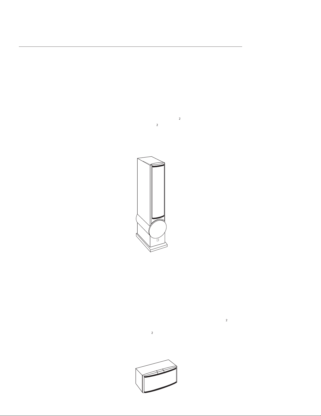
PRODUCT DESCRIPTION
XA 75LE
High-performance fl oor-standing system
Special three-element XA for controlled directivity to
400Hz. 10- inch (250mm) powered subwoofer with
level and corner shape switches for room and program
optimization. The driver complement includes a 1-inch
(25mm) black anodized aluminum-dome tweeter,
fl anked by a pair of 2
1
⁄
2
-inch (60mm) upper midrang-
esand a 6
1
⁄
2
-inch (150mm) lower midrange beneath the
XA cluster. A soft-dome rear-fi ring tweeter is included
for added ambiance Below 100Hz, a 10-inch (250mm)
bass unit and a 300-wattamplifi er provide bass to 34Hz
(-3dB).
XA 55cr
Full-range music- and movie-quality center channel
The XA 55cr center channel is tuned to precisely match
the tonal balance of the XA Towers for seamless fi ve-
channel movie or music reproduction. It shares an iden-
tical three-element XA to the above two models. This
three-way design uses a 1-inch (25mm) black anodized
aluminum-dome tweeter surrounded by two 2
1
⁄
2
-inch
(60mm) midrange units. The array is fl anked by left and
right 6
1
⁄
2
-inch (150mm) bass units in a sealed enclosure.
Bass extension is to 50Hz. Video shielding, a placement
switch, and smooth off-axis frequency response allow
placement above or below a TV or in a cabinet.
6
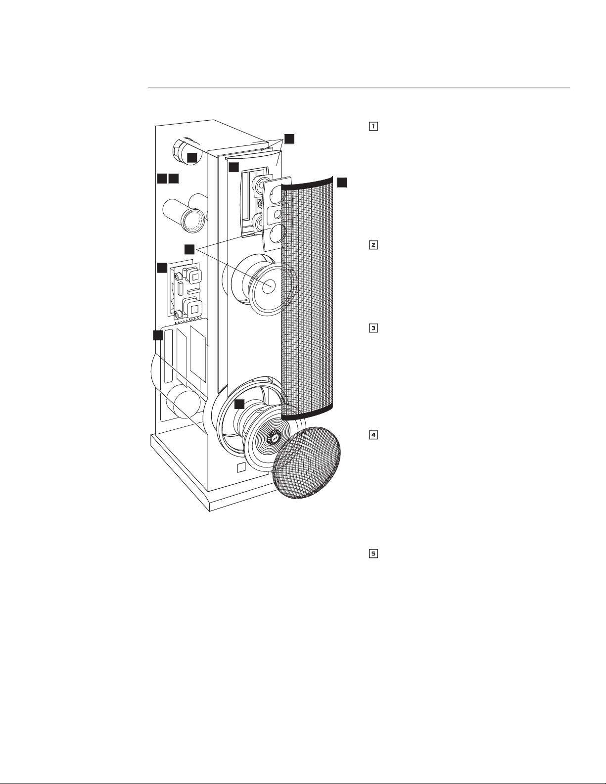
XA FEATURES
1
1
Multielement Expanding Array
Months of study and computer simulation resulted
in a scientifi cally designed three-element array with
idealized dispersion characteristics. The XA’s perfor-
mance is seamless and invariant within any likely
listening position. Controlled directivity beyond
normal vertical angles reduces room involvement,
for a clearer and more detailed image with either
movie or multichannel music sources.
2
2
Integral Powered Subwoofer
An integral subwoofer gives the low-frequency
foundation necessary for music or cinema reproduc-
tion (XA75LE). Inclusion of an amplifi ed subwoofer
allows the upper-range drivers to be optimized for
higher sensitivity.
3
3
Controls for Subwoofer Optimization
Controls on the dedicated subwoofer amplifi er allow
optimization of subwoofer performance to both
the room and program. Parametric Equalization
(XA75LE) allows correction of room acoustic fl aws.
Bass level and subwoofer rolloff shape controls
(via remote in the XA75LE) allow for adjustment as
needed for program material, room, and taste.
4
4
Platform Baffl e
This three-layer sandwich isolates the baffl e from
the cabinet to decrease panel resonances and
coloration—especially in the critical midrange. The
Platform Baffl e consists of materials of varying
density—an extremely dense outer layer to which
the tweeter and bass units are mounted, a “squishy”
neoprene middle layer, and a medium-density inner
layer that attaches to the cabinet.
5
5
Radiused-Edge Baffl e
The elliptical radius on our baffl e edge reduces re-
radiation for a cleaner and smoother response—es-
pecially off-axis. Snell pioneered this technique in
the original Type A speaker system in 1976.
7
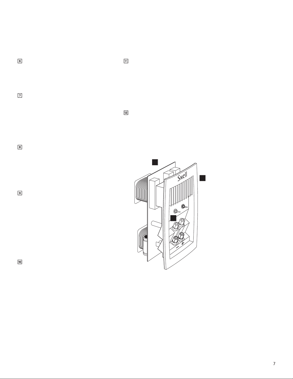
6
6
Grille Design
The custom-perforated metal grille has no frame to
cause degrading refl ections in the upper frequen-
cies. Rubber mounts isolate the grille posts from the
Platform Baffl e.
7
7
Hand-Tuned Crossover
These networks adhere to an “in-phase” or Linkwitz
Reilly design. (Time alignment and coherency are
achieved through the transition region from driver
to driver.) In production, each crossover is individu-
ally tuned by our technicians to within ±0.5dB of
the master reference, assuring an identical sound
balance to our master reference system.
8
8
Handmade Cabinets
Our cabinet department hand assembles each
cabinet, and then hand sands each several times.
Multiple coats of hand-applied fi nishing oils reveal
great depth to the wood grain. The result is a cabi-
net of exceptional workmanship, with sharp corners,
smooth sides, and natural beauty.
9
9
Veneers
We use premium, book-matched veneers in our
oiled cabinets, chosen for grain consistency and
aesthetics. A pair of speakers uses wood veneer
from the same tree, so grain patterns are consistent.
Our cabinet shop sequences the veneer, maintain-
ing a match for the top, right/right, and left/left
sides of each pair of speakers. We even go so far
as to veneer the inside of the cabinet. This way, as
the cabinet undergoes changes in humidity in your
home, it won’t warp or come apart at the edges.
0
0
Placement Switch
This switch “normalizes” the speaker if it is placed in
a cabinet or next to a large object, like a big-screen
TV. This Snell feature assures the proper balance of
your speaker in less than ideal placements.
-
-
Heat Sink/Terminal Plate
Heat-producing crossover components are mounted
to a diecast aluminum heat sink for stable, consis-
tent performance at high power. This large heat sink
also draws heat from inside the cabinet, keeping
critical driver components cooler. The terminal plate
has two sets of fi ve-way gold-plated binding posts
for bi-wiring or bi-amplifying.
=
=
Rear-Firing Tweeter
The rear-fi ring tweeter on the XA75LE models adds
necessary high-end “fi ll” to the soundstage, creating
a broader, deeper stereo image when the speaker is
placed away from a back wall. An on/off switch al-
lows you to defeat the rear tweeter when placed up
against a back wall.
8
PLACEMENT OF YOUR SPEAKER SYSTEM
XA 75LE
The XA 75LE is designed for either freestanding or
boundary placement.
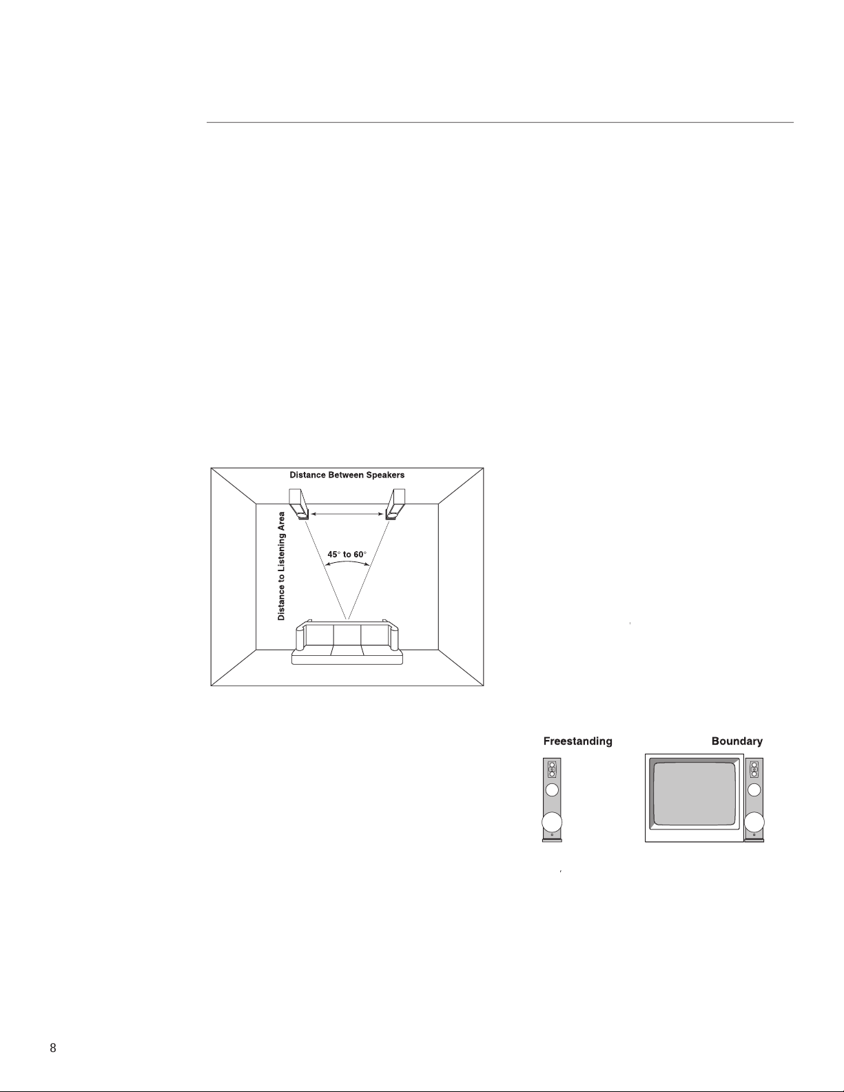
Stereo Image
The distance between the speakers determines the
width of the stereo image. If the speakers are placed too
close together, the image will be too narrow; too far
apart and the blend will suffer, creating a hole in the
middle. When properly placed, your speakers will create
a continuum of “virtual images” from left to right, with
an illusion of sound outside, in front, and behind the
speaker systems.
✦
We recommend an angular separation between 45°
and 60° (when viewed from above).
This is equivalent to a separation between the speaker
systems that is about 85% of the distance to either of
the speakers.
Creation of sounds between the speakers requires some
precise placement. The distance from the left speaker,
right speaker, and center channel to the listener location
should all be as equal as possible. We advise using a tape
measure to equalize these two distances to the primary
listening position. The payoff will be well worth the time
and effort.
Room-Related Bass Effects
Experiment until you fi nd the best overall sound for
your room. Choose a source with a heavy and continu-
ous bass line, repeat a short section until you have a
fi rm impression of it in your mind, and then try another
speaker location. Repeat this process until you are
content with the bass response you are getting. Aim
for even reproduction of each bass note without undue
prominence of any of them. Moving your listening posi-
tion may affect the sound as much as moving the speak-
ers. If practical, try different listening locations as well
as speaker locations. Bass level controls (XA 75LE) will
allow you to help improve the bass balance at whatever
fi nal location you choose. Additionally, the parametric
equalizer will allow you to electronically correct
one major bass aberration per speaker, thus making
placemen even less critical. (See ”Optimizing the Sound”
section).
Boundary Effects
Large surfaces near your speakers will affect the level
of upperbass and lower-midrange frequencies. This can
make voices sound unnatural. A feature to counteract
this is the ”Bass Loading” switch, with positions for
”Normal” or ”Boundary.” Refer to the switch on the
input terminal plate.
Normal or Freestanding
placement refers to a situa-
Normal or Freestanding placement refers to a situa-Normal or Freestanding
tion in which the XA 75LE has at least a 12-inch (30cm)
clearance on all four sides.
✦
Away from large furniture
✦
Not close to walls
✦
Set Boundary switch to Freestanding
Boundary
placement refers to a situation in which the
Boundary placement refers to a situation in which the Boundary
XA Tower is bounded on at least one side by a large
object.
Set Boundary switch to Boundary if:
✦
Placed beside a TV
✦
Placed beside a bookshelf or an audio/video cabinet
✦
Placed next to a wall
See the section entitled “Optimizing the Sound” for
more on adjustments related to these placements.
9
Toe In
Toe in refers to the angling of the speaker systems
toward the listening location. Toe in is a matter of
taste. As the degree of toe in increases, the stereo effect
becomes more sharply defi ned, becoming more like that
of headphones. Toe in also improves the stereo effect for
off-center listeners. Having your speakers aligned with
their backs parallel to the wall gives a more spacious
sound with a less well-defi ned central image.
Toeing in should be the last step in the placement of
your speaker system. After fi nalizing speaker position
and listening location, place the speakers with their
backs parallel to the back wall or cabinet. Experiment
from there, turning the speaker by 10-inch increments
toward the listening area until you achieve the desired
effect.
Setting the Carpet Spikes
Four steel spikes (#5/16-18 thread) are included with
the XA 75LE. Use them to balance the speaker when
placing the XA on carpet.
XA 55cr Center Channel
The center channel keeps musical or soundtrack
information centered in the listening area. Therefore,
its placement relative to the left and right speakers is
critical.
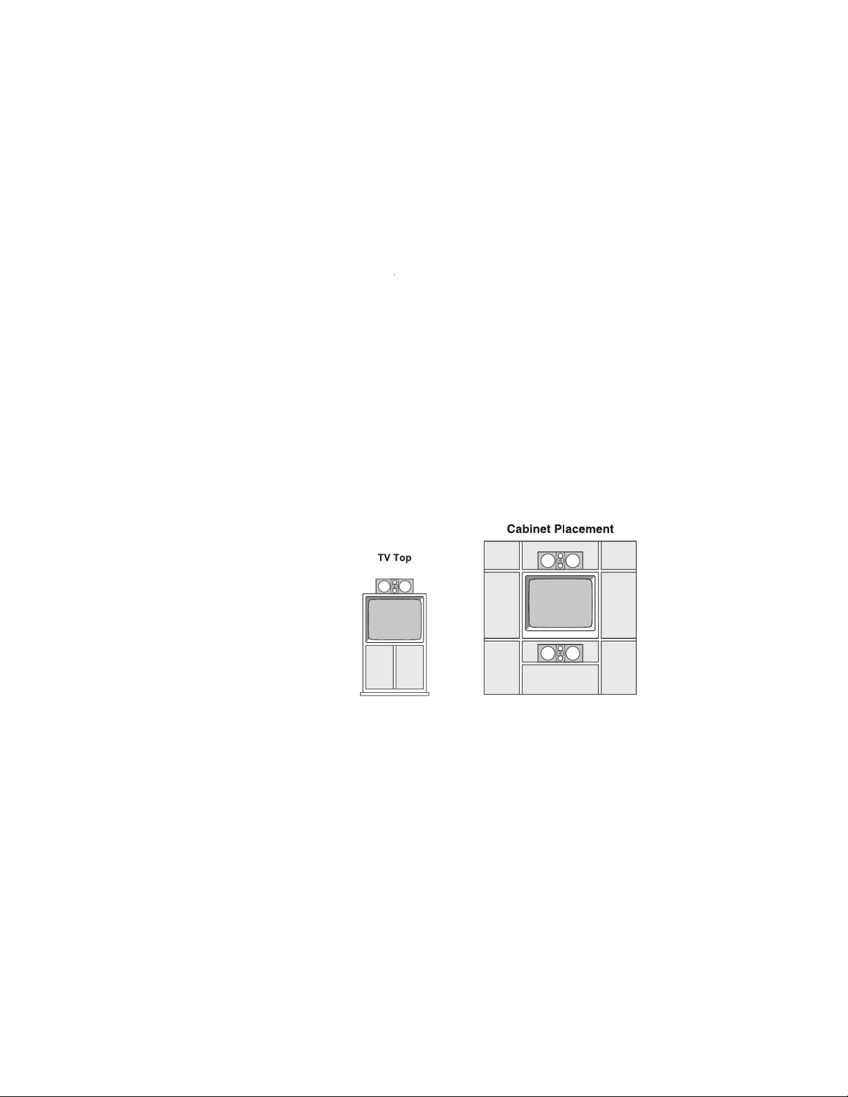
Place the speaker on top of or beneath your TV with its
front edge as far forward as practical. Try to keep the
front of the speaker fl ush with the front of the screen.
When possible, place the height of the XA 55cr near
the tweeter height of the XA Towers (about 40 inches
(1m) above the fl oor). If you need to place the speaker
signifi cantly higher or lower, angle it toward ear level.
The XA 55cr can compensate for either TV top or cabinet
placement. Refer to the switch on the input terminal
plate. This is achieved by the right switch, on the input
terminal plate.
Normal
refers to a situation in which the XA 55cr is:
Normal refers to a situation in which the XA 55cr is:Normal
✦
On top of a 30-inch (76cm) or smaller TV, and the TV
is freestanding in your room
✦
Stand mounted away from boundaries
(If in doubt, use whichever position makes voices sound
more natural.)
Boundary placement refers to a situation in which the
XA 55cr is:
✦
On top of a TV larger than 30 inches (76cm)
✦
On top of a TV that is placed in an audio/video cabi-
net
✦
Below a TV or on a shelf
(If in doubt, use whichever position makes voices sound
more natural.)
Center channel—Setting the Placement Switch
✦
TV top placement: Set the Placement Switch to
NORMAL.
✦
Voices sound ”thin”: Set the Placement Switch to
NORMAL.
✦
Cabinet placement: Set the Placement Switch to
BOUNDARY.
✦
Voices sound ”thick” or ”heavy”: Set the Placement
Switch to BOUNDARY.
Attaching the Bumpers
Four rubber bumpers are included with the XA 55cr.
Stick them to the bottom of the speaker cabinet to
protect the fi nish on your TV.
10
CONNECTING THE SPEAKERS
For All Models
Choosing Cable
We recommend minimum 16-gauge high-quality
speaker cable or thicker for runs up to 25 feet (8m) and
12-gauge wire or thicker for longer runs. (We use a
custom-confi gured 12-gauge oxygen-free cable in our
crossover networks.)
Connecting with Bare Wire
Insert bare wire into holes and tighten.
Connecting with Banana Plugs, Spade Lugs, or Pins
The binding posts accept standard banana plugs and
pins, and can accommodate 5/16” or larger spade lugs.
Warning!
To prevent electrical shock, always switch off
the amplifi er or receiver when making connections to
the speaker system.
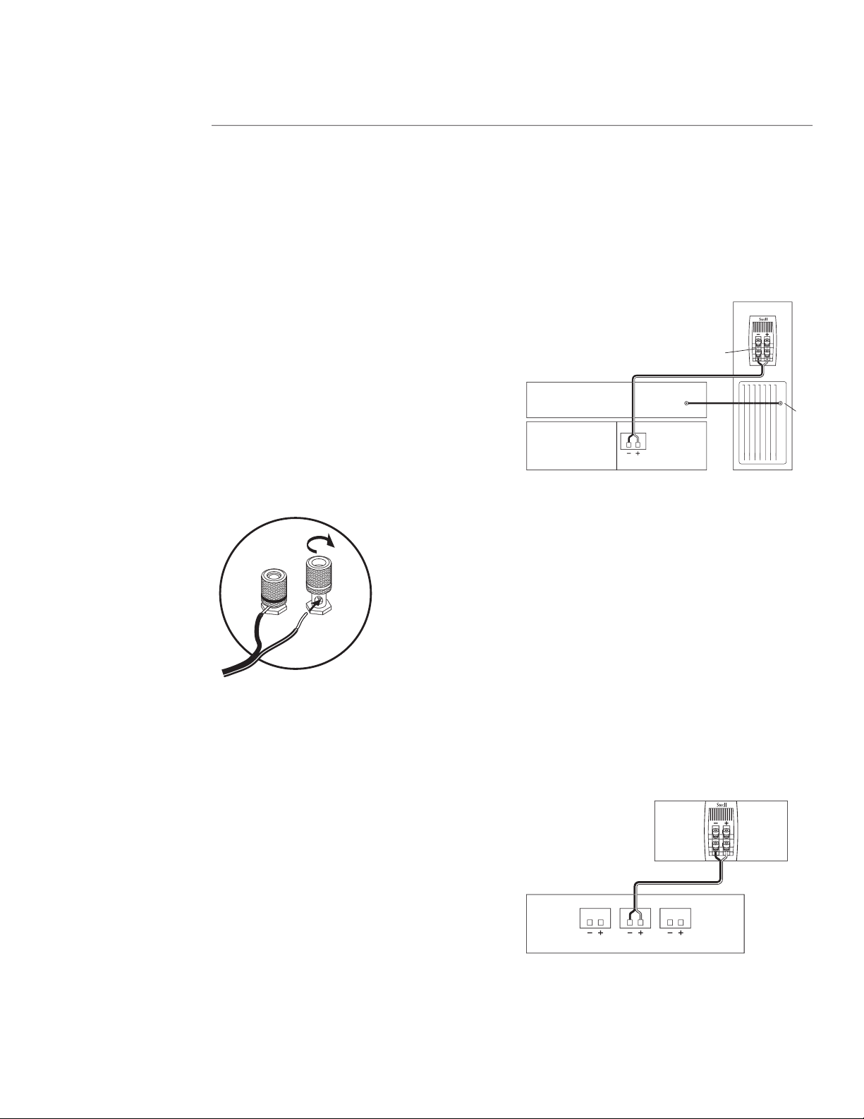
Connecting the XA75LE
Basic Connections
✦
Keep the speaker terminal jumper straps in place.
✦
When making connections, be sure to connect + to +
(red) and – to – (black).
XA75LE
amplifier or receiver
surround processor
speaker terminal
jumper straps
LFE
input
sub
out
Connecting the XA 55cr
Connecting the XA 55cr to a Surround Processor
✦
Select the ”small” or ”normal” setting on your
receiver or processor for the center channel. This
routes all bass information (typically below 120Hz)
to the subwoofers of the XA75LE.
✦
When making connections, be sure to connect + to +
(red) and – to – (black).
Match the sound levels of each speaker.
✦
Your home theater system most likely includes a test
signal that simplifi es level matching. Refer to the
instructions provided with these electronics.
surround sound receiver or amplifier
left front center front right front
XA55cr
11
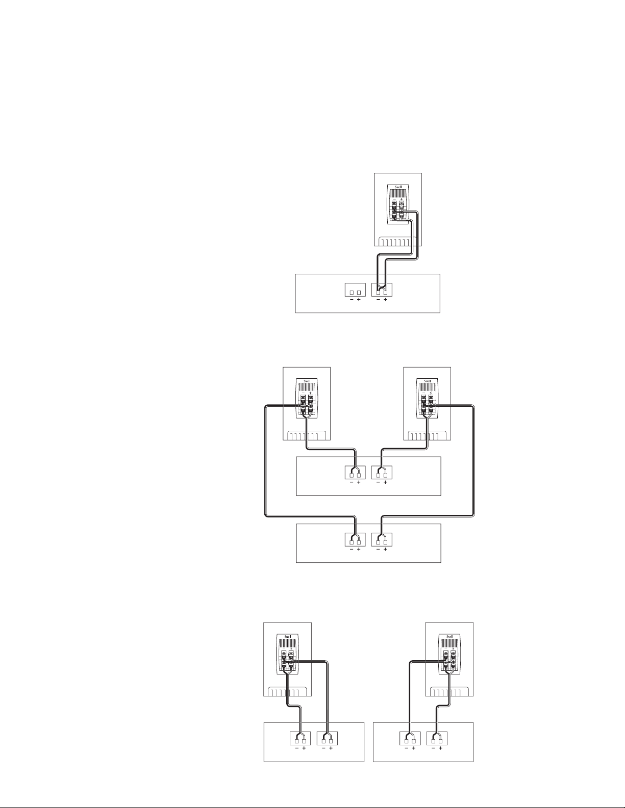
Bi-Wiring and Bi-Amping (All Models)
Bi-Wiring
1.
Use equal lengths of the appropriate wire when
bi-wiring each speaker. Consult your dealer for cable
options.
2.
Unscrew both sets of terminals and remove the
jumper straps.
Bi-Amplifying
Using one amplifi er for the bass, and one for the high
end:
1.
Unscrew both sets of terminals and remove the
jumper straps.
2.
Connect the cables from the bottom set of termi-
nals to the low-frequency amplifi er driving the bass
units.
3.
Connect the cables from the top set of terminals to
the highfrequency amplifi er driving the tweeters.
4.
Do not use an external crossover. It will interfere
with the phase and frequency response.
Using One Amplifi er for Each Speaker
Make sure that the amplifi ers are identical.
1.
Unscrew both sets of terminals and remove the
jumper straps.
2.
Connect the cables from the bottom set of terminals
to the fi rst amplifi er’s right channel.
3.
Connect the cables from the top set of terminals to
the fi rst amplifi er’s left channel.
4.
Repeat steps 2 and 3 above for the second amplifi er.
XA 75LE
amplifier or receiver
left speakerright speaker
low-frequency amplifier
high-frequency amplifier
left speakerright speaker
right channel amplifier left channel amplifier

12
MULTICHANNEL SYSTEMS
The growth of multichannel formats has greatly in-
creased our opportunity for realism and involvement in
reproduced movies and music. Unfortunately, it has also
complicated system setup.
The next sections explain how to connect the Snell
XA 75ps and XA 55cr in a multichannel system and how
to confi gure your surround processor. Note: We make
assumptions about your surround processor based on
what is typical in the market. Consult your processor’s
manual for the specifi cs.
Usually, the XA 75LE will be connected in the same way
as a normal full-range speaker. Although it contains a
powered subwoofer, full crossover is included, and an
external crossover is neither necessary nor desirable. In a
two-channel system, they will be connected as any other
system, with the exception of the need for a power
connection to the tower’s subwoofer amplifi er. A stereo
power amplifi er or two monoblock amplifi ers will feed
full-range signals to the multiway binding post inputs.
If used with a home theater system, the most probable
confi guration will be that the left and right towers are
larger than center and surround speakers and therefore
will have more bass extension and bass power-handling.
You will then want to use the towers as the subwoofers
for the other channels. Still, this will be accomplished
via the normal speaker-level inputs.
Most multichannel processors have setup options that
designate each channel’s loudspeaker to be “Large” or
“Small.” When set to “Small,” the bass for that chan-
nel will be sent to another channel that is designated
“Large,” or perhaps to a subwoofer. Set the processor so
that the front left and front right channels are ”Large”
and all other channels are “Small.” Generally, the bass of
the left surround will go to the left front channel, the
bass of the center channel will split equally between left
and right front, etc. This is the ideal confi guration. One
benefi t is that you will have stereo bass; whereas, with
virtually all processors, any system using a subwoofer
will have mono bass.
Use with External Subwoofers
First, Should You?
Unless an external woofer has more surface area than
the twin 10-inch units within a pair of XA 75ps’s, you
are better off not using it. It will reduce the output ca-
pability compared to the alternative of sending all bass
to the active towers.
If you already have a subwoofer 18-inches or larger,
then it might be worthwhile to use the subwoofer as an
LFE-only channel. (See page 13 for discussion of ”LFE
Input.”) The rest of the system will be still be confi g-
ured as above with the left front and right front towers
designated as “Large.”
✦
Select the ”Large” setting on your receiver or proces-
sor for your main speakers. This routes all bass
information (typically below 120Hz) to your XA Tow-
ers.
✦
Select the ”Small” or ”Normal” setting on your
receiver or processor for your center and surround
channels. This routes all bass information (typically
below 120Hz) to the XA Towers, where it will be
directed to the built-in subwoofers.
Match the sound levels of each speaker.
✦
Your home theater system most likely includes a test
signal that simplifi es level matching. Refer to the
instructions provided with these electronics.

13
LFE Input
LFE (Low-Frequency Effects) refers to the “.1” channel of
a “5.1” channel recording. Normally, all signals will come
to the active towers via the normal speaker-level inputs.
However, your Snell XA 75LE’s include an alterna-
tive line-level input for bass signal connection. If your
processor allows you to feed all fi ve-channel bass to the
front left and right channels, and by so doing leaves
only the LFE (.1 channel) at the processor’s subwoofer
output, then a coaxial lead can be run to each tower’s
LFE input.
To understand its use, a little background about mul-
tichannel formats is in order. Dolby® AC-3 and other
5.1 systems are confi gured as fi ve full-frequency range
channels and one additional bass-only channel dubbed
the .1 channel. Since the fi ve channels are full range,
there is no restriction of what type of signals can go
into each. Certainly, the bass frequencies of the back-
ground music of a movie will be sent to each channel in
line with all other components of the musical mix.
Explosions and sound effects are another story. It
evolved in movie cinema practice that theater own-
ers wanted a separation of normal soundtrack material
from explosions and effects. This separate track became
known as the LFE or Low Frequency Effects channel
(later the .1 channel). Theater owners could then decide
if they wanted to invest in large theater subwoofers. If
they decided not to invest, they knew that explosions
and such would not be overloading the main system
because they were on a separate channel that could be
ignored.
In order to have adequate headroom for effects, Dolby
specifi es that, after decoding and D to A conversion, the
“.1” channel should be boosted 10dB. Whatever level the
other fi ve channels can achieve, the .1 channel has the
headroom to play up to 10dB louder. Hopefully, the re-
cording engineers will use this extra headroom sparingly.
Unfortunately, the recording of the .1 channel seems to
always be recorded at its maximum level. This can lead
to problems of balance with a normal home theater
system for the following reason: If small speakers are
used with a subwoofer, the subwoofer does double duty
by reproducing a combination of the bass from the fi ve
channels (music and dialog) and the .1 effects channel.
For the music to sound full and balanced, an exact set-
ting of subwoofer level is required. This might be a gain
setting that often reproduces the .1 channel (potentially
10dB louder) at too high a level, causing overdrive or at
least an excessive effects level.
Some processors are now giving setup options that al-
low trimming of the LFE from Dolby-specifi ed full gain
(+10dB) down to a lesser level. The music and cinema
XA Towers also allow you to set LFE level
if you use
a
if you use a if you use
separate LFE input with its own level adjustment poten-
tiometer. This control is calibrated relative to a processor
with the Dolby-required +10dB LFE gain. That is, setting
it to 0 will give the same overall level. Setting it to -8
would be 8dB less than ”normal,” which is in fact 2dB of
gain relative to other channels. (The LFE gain calibration
marks assume your power amplifi er has a voltage gain
of about 26dB.)
This will allow you to control the LFE level independently
of other bass. When the LFE mix-level knob is set to 0dB,
LFE material will be reproduced at the full Dolby-speci-
fi ed mixed level. Settings less than 0dB will change the
proportion of the effects level (explosions and the like)
to music bass levels. This is best set by fi nding a disc
with a preponderance of LFE energy and setting the
knob until the balance between explosions and the rest
of the soundtrack seems “realistic.”
Hint:
One way of
Hint: One way of Hint:
determining a good level is to set it to give (at a typical
loud listening level) a bit of gut feel to the explosions
and gun shots. Extreme settings will become fatiguing
over time.
The above procedure is by no means mandatory. If
you do not wish to use separate connections for LFE,
most processors will send it to any channels designated
“Large” with a confi guration choice of “no subwoofer.”
In all cases, it is important to consult the processor
manual because some manufacturers have different
ºinterpretations of what these designations mean.
14
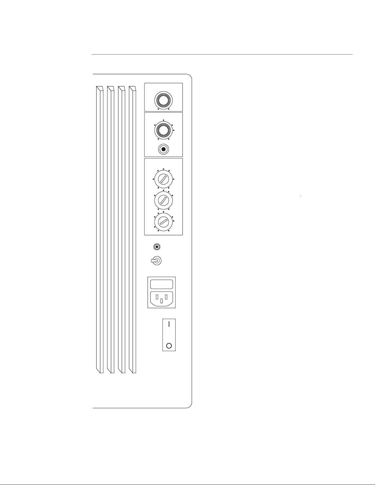
OPTIMIZING THE SOUND
LFE LEVEL
LFE INPUT
REMOTE LINK
POWER
ON
ALWAYS
ON
FUSE
T5A
250 V
60 HZ
120 V
550 W
MUSIC SENSE
AUTO
-8
-10
-12
-3
+3
MIN. MAX.
0
PARAMETRIC EQ
0
-2
LEVEL
(dB)
BANDWIDTH
(0ct)
+2
-5 +5
0.9
0.5
0.2 1.5
1.2
1.0
-10 +10
FREQ.
(Hz)
50
36
30
32
100
65
40
80
OVERALL
BASS LEVEL
OFF
Subwoofer Amplifi er Settings
The amplifi er of the XA 75LE contains a number of rear
panel controls, some of which should be set upon instal-
lation and then generally left alone. Note: In the XA75LE
the remote control contains additional controls for user
adjustment according to taste or program material.
It is best if a qualifi ed installer aids in this initial setup,
hopefully with a 1⁄3-octave real-time spectrum analyzer
and a pair of good ears.
Overall Bass Level
This control sets gain for the bass amplifi er that deter-
mines bass level for the normal (speaker level) input and
also the LFE linelevel input.
Note:
In the XA 90ps, overall
Note: In the XA 90ps, overall Note:
bass level is a combination of the levels set by this knob
and by the remote control. Use the remote control to set
the amplifi er to the 0 position. Adjust the bass level to
give a solid but not overblown bass level. Confi rm this
on a variety of program material. If using a spectrum
analyzer, set to a level so that frequencies below 100Hz
are fl at (or up to 3dB up from fl at). The remote control
will then give a range of ±6dB in 2dB steps from this
central position.
Parametric Equalizer
The XA 75LE is unique in including a bass parametric
equalizer. Through several years of experience with the
amazing RCS1000 digital equalizer, we have learned
fi rsthand the damaging effects of the room on bass
reproduction, and how careful equalization can greatly
reduce these effects. The dimensions and materials of a
room create “standing waves.” The locations of speak-
ers and listener relative to these standing waves create
uneven bass response. The parametric equalizer of the
XA 75LE allows you to pick the room’s dominant bass
problem and correct it. The end result is bass response
that will be more even, more musical, and less “reso-
nant.”
The term parametric equalizer stems from the fact that
all parameters of an equalizer section are adjustable.
This includes bandwidth (also called Q), frequency, and
level. With the parametric equalizer, you have the option
of making broad effects (more or less low bass; more or
less mid-bass) or tackling narrow band effects, such as
notching out a room resonance at 70Hz.

15
Although such a system could be tuned via a skillful ear,
it is better to enlist the help of a real-time analyzer. This
is a piece of instrumentation that analyzes the spectrum
of any signal received by the microphone. Pink noise
(which has a fl at perceived spectrum) is fed from the
instrument to the input of the amplifi er or processor.
The resulting spectrum will show room effects. The para-
metric analyzer can then be adjusted to dramatically
improve the typical room response. Correcting the room
response will create a more even, musical, and faster-
paced bass performance.
To make an adjustment, fi rst choose the aberration to
correct, then match the fi lter to its frequency. Start-
ing with extreme settings of the other two controls
(highest Q and full cut or boost) can most easily do
this. Then, while watching the spectrum analyzer, the
frequency can be adjusted up and down until your cor-
rection frequency and aberration frequency are seen to
coincide. This adjustment of bandwidth and level (+ or
–) will fl atten the response. Caps are provided to seal the
parametric controls once they are optimally set.
Hints:
✦
Live with the system for awhile to learn its bass
character. Then tune to correct its dominant fl aw.
✦
Measure the bass of each channel over a variety of
positions encompassing the listening area. Correct
for the average curve of the area.
✦
Use your ears to confi rm the fi nal settings. Dial in
the boost or cut amount by ear. Don’t worry if the
fi nal setting disagrees somewhat with the “best”
setting according to the spectrum analyzer.
✦
Adjustment of the parametric equalizer may require
further adjustment of bass level. Juggle the settings
of one control against the other.
✦
It is important to have a good match between the
fi nal response of both channels.
10.00
5.00
2.00
-2.00
-5.00
-10.00 10 100 1K
Frequency (Hz)
0
10.00
5.00
2.00
-2.00
-5.00
-10.00 10 100 1K
Frequency (Hz)
0
10.00
5.00
2.00
-2.00
-5.00
-10.00 10 100 1K
Frequency (Hz)
0

16
XA75LE Crossover Controls
Setting the Placement Switch
(Input Terminal Plate, far left switch)
Freestanding placement:
Set the Placement Switch to NORMAL.
Boundary placement:
Set the Placement Switch to BOUNDARY.
Asymmetrical placement:
Based on your room layout, you might fi nd that one
speaker performs best in the BOUNDARY setting, and
the other in the NORMAL setting.
Setting the Treble Level
(Remote Control)
The Treble buttons on the remote control adjusts the
“brightness” of the XA 75LE.
✦
Press the Treble/Boost button on the remote control
to increase the high frequency output in situations
in which the sound is dull.
✦
Press the Treble/Cut button on the remote control to
decrease the high frequency output in situations in
which the sound is overly bright, especially in highly
refl ective rooms.
✦
The + position is closer to ”anechoically fl at,” al-
though much recorded music will be preferred in the
- position.
✦
The - position is similar to a processor cinema ”re-
EQ” setting.
Setting the Rear-Firing Tweeter (far right)
The rear-fi ring tweeter adds spaciousness and ambiance
to the soundstage, and is particularly effective when the
XA75LE is placed at least 12 inches (30cm) from a back
wall.
Turn the Rear-Firing Tweeter OFF When:
✦
The XA Tower is placed directly against a back wall.
✦
The soundstage sounds too bright for your taste.
Center Channel—Setting the Placement Switch
TV top placement:
Set the Placement Switch to NORMAL.
Cabinet placement:
Set the Placement Switch to BOUNDARY.
OPTIMIZING THE SOUND (CONT.)
Bass Shape Control
The rolloff rate and the shape of the low-frequency
corner of a subwoofer affect its sound. For example, a
subwoofer with a “soft” corner and a gradual rolloff rate
below its range of operating frequencies will gener-
ally give a tight and rhythmically “fast” character. A
system with a low-frequency corner that is squarer
and rises slightly before falling off quickly will provide
a more robust low-frequency sound. Additionally, the
faster rolloff will give a better compromise in terms
of apparent bass output versus woofer power capabil-
ity. The Snell XA 75LE via the remote control. Some
people prefer the “Reference” position for music and the
“Cinema” position for movies. Try either setting and use
whichever one suits your mood, your room acoustics, or
your program material.
95
90
85
80
75 20
Frequency (Hz)
10050
reference
cinema
17
SPECIAL FEATURES
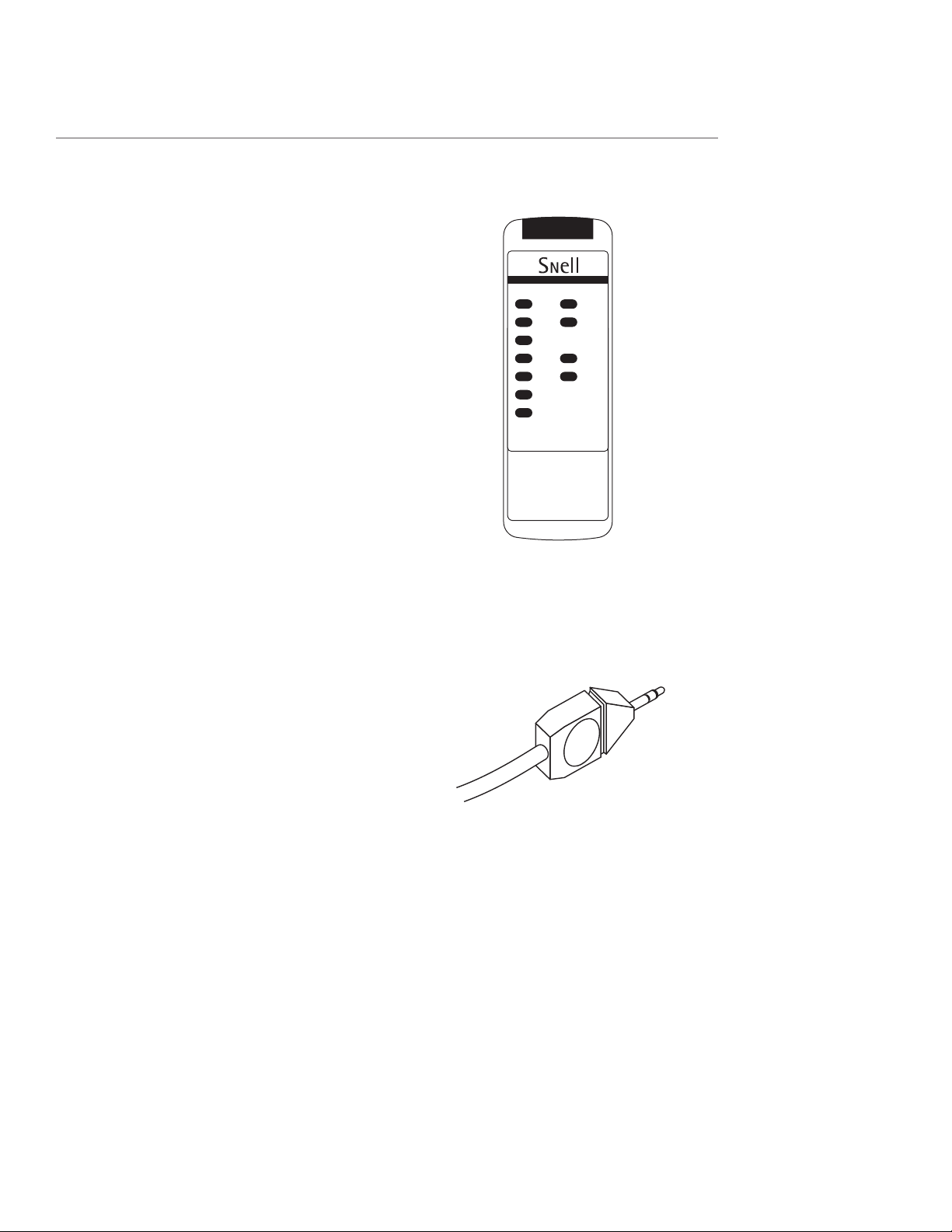
Infra Red Control, Command Cable
The remote control for the XA 75LE uses Infra Red (IR)
to send commands to both speakers. Generally, both
speakers will see commands through uninterrupted dis-
tances of up to 30 feet. Sometimes, one of the speakers
might not see the IR signal, so we have included a cable
to transfer commands from one tower to the other.
You might fi nd a time where you are at the limits of
reception, with one speaker blocked, or perhaps aiming
toward one system and away from the other. In these
cases, the system that receives the commands will pass
them on to the other, thus assuring the best reception
and that the two speakers remain in sync.
Connect the supplied cable from speaker to speaker
through the jacks marked “remote link.” If a longer cable
is required for a special routing or for running wires
through walls, it can be custom-made using well-shield-
ed coaxial and standard mono 1⁄8-inch minijacks.
The control handset gives you control of bass level (in
2dB steps) of bass rolloff shape, and of treble level.
Turn On Mode
The XA 75LE include a feature for automatic turn on.
The subwoofer amplifi er will come out of its low-power
standby mode when it senses a signal. A multicolored
LED will designate what state the amplifi er is in. Yellow
indicates standby, and green indicates on. After the
signal ceases, the system will revert to standby mode in
approximately 8 to 10 minutes. Both speakers will not
necessarily turn off at the same moment. As an alterna-
tive to automatic turn on, the speaker can be set to be
always on. To choose between these two options, use
the switch marked “MUSIC SENSE-AUTO/ALWAYS ON.”
In some systems, the electrical noise fl oor (due to hum,
refrigerator, or furnace-turn-on pops, etc.) is such that
Music Sense- Auto turn on is erratic. In this case, we
recommend that the switch be set to ALWAYS ON and
manual switching via the main power switch be used.
Power On
The main power switch is situated below the power
input lead. It is a rocker-type switch marked with a ”1”
and a ”0.” Pressing the end marked ”1” will turn on the
main power to the system. Some people prefer to turn
off the main power if they know that they will be gone
from the house for an extended period of time.

18
SPECIAL FEATURES (CONT.)
Amplifi er Protection
The subwoofer amplifi er contains protection against
fault conditions of excessive DC output or thermal
overload. If triggered, the rear panel LED will glow red.
Protection circuitry is not self-resetting. To reset, turn
off the main power switch, wait several minutes for the
unit to cool (if hot), and restore the power. If this does
not reset the LED to yellow or green, disconnect the
input and repeat. If this still does not remedy the fault,
contact your dealer or Snell Acoustics for service. If
disconnecting the system’s input restores the system to
normal, associated equipment is suspect and should be
checked.
LISTENING LEVELS AND
POWER-HANDLING
The power recommendation for the system assumes you
willoperate the amplifi er in a way that will not produce
distortion. All speakers can be damaged by a modest
amplifi er if it is producing distortion. If you hear a gritty
noise or other signs of strain, turn down the volume.
Prolonged or repeated operation of your speakers with a
distorted signal can cause damage that is not covered by
the warranty.
HOW TO CARE FOR YOUR
SPEAKERS
For Painted Finishes
Including fronts, backs, bases, and metal grilles.
✦
Use a soft terry cloth towel slightly dampened with
water or a diluted mild detergent. The towel should
be just damp enough to wipe the surface clean
without leaving a trail of moisture.
✦
Do not use abrasive cleaners or any cleaner contain-
ing chemicals harsher than those found in glass
cleaner.
For Oiled Natural Wood Finishes
To remove dust and fi ngerprints, use the same technique
as above.
✦
If your veneer begins to dry, apply a light coat of
rose or lemon wood oil. This should return the wood
to its original richness.
✦
Do not use spray waxes. These will create a buildup
and eventually cause the veneer to appear dull and
lifeless.
Note:
Your veneer’s appearance and color will mature
and perhaps darken over time.
✦
Avoid placing speakers in extreme conditions. If
direct sunlight is unavoidable, be sure that there
is nothing partially covering the veneer in order to
prevent ”tan lines.”
✦
Avoid placing speakers where they could be sub-
jected to standing water. It will cause the wood to
swell, breaking apart glue joints and ruining the air
seal.
Grilles
You can remove the grilles from the speaker system and
wipe them with a damp cloth to remove any dust.

19
LIMITED WARRANTY
For fi ve years from the date of purchase, Snell Acoustics
will repair for the original owner any defect in materi-
als or workmanship that occurs in the drivers (woofer,
midrange, tweeter) of the XA 75LE or XA 55cr without
charge for parts and labor. For two years from the date
of purchase, Snell Acoustics will repair for the original
owner any defect in materials or workmanship that oc-
curs in the amplifi er of the XA 75LE without charge for
parts and labor.
Your responsibilities are to use the system according
to the instructions supplied, to provide safe and secure
transportation to an authorized Snell Acoustics service
representative, and to present proof of purchase in the
form of your sales slip when requesting service.
Excluded from this warranty is damage that results from
abuse, misuse, accidents, shipping, repairs, or modifi ca-
tions by anyone other than an authorized Snell Acous-
tics service representative.
This warranty is void if the serial number has been
removed or defaced.
This warranty gives you specifi c legal rights, and you
may also have other rights which vary from state to
state.
If Service Seems Necessary
Contact the dealer from whom you purchased the
speaker system. If that is not possible, call us at
978-538-6262, or write to:
Snell Acoustics
300 Jubilee Drive, POB 3717
Peabody, MA 01961-3717
We will promptly advise you of what action to take. If
it is necessary to return your speaker system to the fac-
tory, please ship it prepaid. After it has been repaired, we
will return it freightprepaid in the U.S. or Canada. Reuse
your original packaging for all shipping.

300 Jubilee Drive, P.O. Box 3717
Peabody, MA 01961-3717
phone: 978-538-6262
fax: 978-538-6266
email: info@snellacoustics.com
web: www.snellacoustics.com
©2005 Snell Acoustics.
All Rights Reserved.
”Dolby” is a trademark
of Dolby Laboratories.
Confi dential Unpublished
Works. ©1992-1997 Dolby
Laboratories, Inc.
Specifi cations are subject
to change without notice.
Covered by patents issued
and or pending.
Part #542-1005-1
This manual suits for next models
2
Table of contents
Other Snell Speakers manuals

Snell
Snell QBx 20 Monitor User manual

Snell
Snell AMC 560 User manual

Snell
Snell XA 55cr User manual

Snell
Snell QB 25 Series User manual

Snell
Snell OH-S7 User manual

Snell
Snell AMC550mp User manual

Snell
Snell AMC 360 User manual

Snell
Snell IW-T7 User manual

Snell
Snell AMC 6030 User manual

Snell
Snell AMC 2000 User manual


