Snell PYXIS User manual

PYXIS
System User Guide
User Guide
Issue: 2.3
www.snellgroup.com

HU-PYXIS 2
PYXIS
System User Guide
Contents
1Introduction 7
2Pyxis Boards 8
2.1Frame/Chassis Parts 8
2.2Rear Panels 8
2.3MODULES 9
3Installation 10
3.13U Frame 10
3.1.1Specification 10
3.1.2Ventilation 10
3.1.3Before Switch-On. 11
3.1.43U Frame Layout 11
3.1.5Fitting and removing the frame door 11
3.1.6Inserting and removing modules 12
3.1.73U Power Supply Modules 15
3.21U 17
3.2.1Ventilation 17
3.2.2Internal Layout 17
3.2.31U Power Supply 18
4Control Options 19
4.1Dual Redundant Controller Operation 19
4.22449: Nebula Controller 20
4.2.1Functionality 20
4.2.2The System Database 21
4.2.3Version Numbers 21
4.2.4Control Protocol Options 22
4.2.52449 Configuration (Switches & Headers) 23
4.3Nucleus Control System 29
4.3.12450 User Interface 29
5Control Interface 30
5.13U Frame Control Connections 31
5.1.1Interconnections and Safety 31
5.1.2Port 1 RS422 or EXP_IN 31
5.1.3Port 2 Config (Database Upload Configuration Mode) 34
5.1.4Port 3 RS422 36
5.1.5AES/LTC & RELAY 37
5.1.6Audio Reference (UNBALANCED AES, BALANCED AES) 38

Issue 2.3 3
PYXIS
System User Guide
5.1.7Video Reference (REF1, REF2, REF3) 38
5.1.8Ethernet (CON1 & CON2) 39
5.1.9Expansion (EXP_IN, EXP_OUT) 40
5.21U Frame Control Connections 41
5.2.1Interconnections and Safety 41
5.2.2Pin-Outs 41
5.2.3Ethernet 41
5.2.4Port 3 Serial Comms/AES 42
5.2.5Power 42
5.2.6Video Reference 42
6Signal Modules 43
6.1Digital Video 43
6.1.1Digital Video Routing Modules 9200 Range 43
6.1.2User Interface 44
6.1.3Specifications 46
6.2Audio 49
6.2.1Terminology 49
6.2.2MADI 50
6.2.3Audio Modes 50
6.2.4Internal Expansion 52
6.2.5External Expansion 53
6.2.6Audio Port Numbering 54
6.2.7Audio Modification 56
6.2.8Audio Specifications 57
6.3AES 59
6.3.1User Interface 59
6.3.2AES Module with Non-Audio Signals 64
6.4Analogue Audio 65
6.4.1User Interface 65
6.5RS422/Timecode 69
6.5.1RS422 Routing 9600 Range 69
6.5.2Timecode 69
6.5.3User Interface 70
7Rear Panels 72
7.1Video Rear Panels 72
7.1.2Rear Panel Port Mapping for Digital Video 73
7.2Audio Rear Panels 76
7.2.19105: Balanced Audio Rear Panel 76
7.2.29107 9108: Unbalanced Audio Rear Panels 80
7.3RS422 Rear Panels 81
7.3.1Connector Layout 82
7.4Timecode Rear Panels 83
7.4.150 way D type connector pinout 83

HU-PYXIS 4
PYXIS
System User Guide
7.51U Rear Panels 85
8Break Out Boards 86
8.1RS422 86
8.1.1Connections & Port Mapping 87
8.2Audio 89
8.2.1Connecting Analogue Audio 90
8.2.2Connecting AES 91
8.2.3Connector Pin Out 93
9Appendices 94
9.1Audio Break Out Port Mapping 94
9.1.1ANALOGUE BREAKOUT: Port Mapping 95
9.1.2AES BREAKOUT: Port Mapping 98
LIST OF FIGURES
Figure 1: Snell Pyxis 3U Router .............................................................................................................. 7
Figure 2: 3U Frame Air Flow ................................................................................................................. 10
Figure 3: 3U Frame - Layout ................................................................................................................. 11
Figure 4: Removing the front door......................................................................................................... 12
Figure 5: Card Retainer (3U)................................................................................................................. 12
Figure 6: Removing Modules................................................................................................................. 13
Figure 7: 3U Fan Module....................................................................................................................... 13
Figure 8: Replacing a Fan Module ........................................................................................................ 14
Figure 9: Power Supply (3U) ................................................................................................................. 15
Figure 10: Alarm Relay Trigger Enable ................................................................................................. 16
Figure 11: 1U Air Flow........................................................................................................................... 17
Figure 12: 1U Frame Layout ................................................................................................................. 17
Figure 13: Pyxis Control Card Options.................................................................................................. 19
Figure 14: About Nebula Editor Screen Shot ........................................................................................ 21
Figure 15: 2449 Nebula Controller Configuration Components ............................................................ 23
Figure 16: 2449 Base Card - Switch Locations..................................................................................... 25
Figure 17: 2449 Controller: Master/Slave Settings ............................................................................... 26
Figure 18: 2449 Controller: Ethernet Port Configuration....................................................................... 27
Figure 19: 2449 Controller: Diagnostic LEDs ........................................................................................ 27
Figure 20: 2450 Controller: Diagnostic LEDs ........................................................................................ 29
Figure 21: Pyxis Control Interface - System Connection Example ....................................................... 30
Figure 22: Pyxis Control Rear Panel Connectors ................................................................................. 31
Figure 23: Configuration of Port 1 to RS422 with 2449 Controller ........................................................ 32
Figure 24: Port 1 Wiring RJ45 Cable to 9 Way D-Type ........................................................................ 33
Figure 25: 2449 Controller: Port 2 Configuration .................................................................................. 34
Figure 26: 2449 Controller: Port 3 Configuration .................................................................................. 36
Figure 27: Rear Panel Ethernet Ports ................................................................................................... 39
Figure 28: Pyxis Expansion - System Diagram..................................................................................... 40
Figure 29: 2451 Slave Controller Configuration .................................................................................... 40
Figure 30: Pyxis 1U Frame Rear Panel................................................................................................. 41
Figure 31: 9200 Range Modules: Switches and LEDs.......................................................................... 44
Figure 32: Audio Modules: Internal Expansion Block Diagram............................................................. 53
Figure 33: Audio Modules: External Expansion .................................................................................... 54
Figure 34: AES Module: LEDs and Switches........................................................................................ 59
Figure 35: AES Module: Configuration and Status ............................................................................... 59

Issue 2.3 5
PYXIS
System User Guide
Figure 36: AES Module: Menu Flow Diagram....................................................................................... 62
Figure 37: AES Module: Input Monitoring ............................................................................................. 62
Figure 38: AES Module: Normal Mode Example .................................................................................. 63
Figure 39: AES Module: Headphone Socket & Control ........................................................................ 63
Figure 40: Routing Dolby E with AES Module(s)................................................................................... 64
Figure 41: Analogue Audio Module: LED's and Switches..................................................................... 65
Figure 42: Analogue Module: Configuration and Status ....................................................................... 65
Figure 43: Analogue Module: Menu Flow Diagram............................................................................... 68
Figure 44: RS422/Timecode Modules: LEDs and Switches ................................................................. 70
Figure 45: A Typical Rear Panel Combination ...................................................................................... 72
Figure 46: Pyxis 9100 72 x 72 SDI Rear Panel..................................................................................... 72
Figure 47: Pyxis 9101 34 x 34 SDI Rear Panel..................................................................................... 73
Figure 48: Pyxis 9102 17 x 17 SDI Rear Panel..................................................................................... 73
Figure 49: Digital Video Rear Panel: Module & Rear Panel Combinations: 9100 Port Mapping.......... 74
Figure 50: Digital Vid2eo Rear Panel: Module & Rear Panel Combinations: 9101 Port Mapping........ 75
Figure 51: Digital Video Rear Panel: Module & Rear Panel Combinations: 9102 Port Mapping.......... 75
Figure 52: 9105 ..................................................................................................................................... 76
Figure 53: 9107 ..................................................................................................................................... 76
Figure 54: 9108 ..................................................................................................................................... 76
Figure 55: 9105 36 x 36 (72 Mono) High Density Balanced Audio Rear Panel .................................... 76
Figure 56: 56 Channel MADI - Port Numbering .................................................................................... 77
Figure 57: 64 Channel MADI - Port Numbering .................................................................................... 77
Figure 58: 62 Way D-Type Pin Numbering ........................................................................................... 78
Figure 59: 62 Way D-Type - Audio Pair Layout .................................................................................... 78
Figure 60: 9107 & 9108......................................................................................................................... 80
Figure 61 : RS422 Rear Panels ............................................................................................................ 81
Figure 62: 50 Way D-Type Pin Numbering ........................................................................................... 82
Figure 63: 50 Way D-Type Signal Layout ............................................................................................. 82
Figure 64: 32x32 Timecode rear panel ................................................................................................. 83
Figure 65: 50 Way D-Type Pin Numbering ........................................................................................... 83
Figure 66: 50 Way D-Type Signal Layout ............................................................................................. 84
Figure 67: 9124: RS422 Breakout System Diagram ............................................................................. 86
Figure 68: 9124 Breakout Panel – IDC Connector Labelling ................................................................ 87
Figure 69: 9124 RS422 Breakout Panel Port Numbering ..................................................................... 87
Figure 70: Port Numbering for Breakout of 9121 Rear Panel ............................................................... 88
Figure 71: 9128: Audio Breakout System Diagram............................................................................... 89
Figure 72: 9128 Analogue Audio Breakout Wiring and Port Numbering............................................... 91
Figure 73: 9128 AES Breakout Wiring and Port Numbering ................................................................. 92
Figure 74: 9128 Breakout Panel Silkscreen Labelling .......................................................................... 93
Figure 75: 9128 Audio Break Out Panel - Metalwork Labelling ............................................................ 93
Figure 76: Analogue Example Table ..................................................................................................... 94
Figure 77: AES Example Table ............................................................................................................. 95
Figure 78: Analogue Audio Breakout Connection ................................................................................. 95
Figure 79: AES Breakout Connection ................................................................................................... 98

HU-PYXIS 6
PYXIS
System User Guide
LIST OF TABLES
Table 1: Frame/Chassis Part Numbers ................................................................................................... 8
Table 2: Rear Panels............................................................................................................................... 8
Table 3: Signal Modules .......................................................................................................................... 9
Table 4: Front Door LEDs (3U) ............................................................................................................. 13
Table 5: Front Door LEDs (1U) ............................................................................................................. 18
Table 6: 2445 Nebula Control Card: Config. Switch Functionality ........................................................ 24
Table 7: 2445 Nebula Control Card: LED Functionality ........................................................................ 25
Table 8: 2449 Controller: LED Functionality.......................................................................................... 28
Table 9: 2450 Controller: LED Functionality.......................................................................................... 29
Table 10: Port 1 (RS422 Modes) Pin Out.............................................................................................. 33
Table 11: Port 1 EXP_IN Mode Pin Out ................................................................................................ 34
Table 12: RS232 Port Pin Out and Cable Requirements...................................................................... 35
Table 13: Port 3 Pin Out ........................................................................................................................ 37
Table 14: AES/LTC & Relay Port Pin Out ............................................................................................. 37
Table 15: Ethernet Ports Pin Out .......................................................................................................... 39
Table 16: 1U Frame Port 3 Pin Out....................................................................................................... 42
Table 17: 9200 Range Modules: LED Functions .................................................................................. 44
Table 18: 9200 Range Modules: Switch Functionality .......................................................................... 44
Table 19: 9200 Range Modules: Control level Settings ........................................................................ 45
Table 20: 9200 Range Modules: DIP Switch Settings .......................................................................... 45
Table 21: 3G/HD/SD Reclocking Module Specification ........................................................................ 46
Table 22: 3G/HD/SD Non-Reclocking Modules Specification............................................................... 47
Table 23: SD Non-Reclocking Modules Specification........................................................................... 48
Table 24: Audio Terminology ................................................................................................................ 49
Table 25: Audio Mode Switch Settings.................................................................................................. 50
Table 26: Transcoder Mode Port Numbering ........................................................................................ 52
Table 27: Audio Modules: Port Numbering with Nebula Controller....................................................... 55
Table 28: Audio Modules: Port Numbering with Nucleus Controller ..................................................... 56
Table 29: Audio Modules: I/O Specification .......................................................................................... 57
Table 30: Audio Modules: Digital Input to Analogue Output Specification............................................ 58
Table 31: Audio Modules: Analogue Input to Digital Output Specification............................................ 58
Table 32: AES Module: Status LED Functionality................................................................................. 60
Table 33: AES Module: Configuration Switch Functionality .................................................................. 60
Table 34: AES Module: Menu Switch Functionality .............................................................................. 60
Table 35: AES Module: Menu Modes.................................................................................................... 61
Table 36: AES Module: Input Status LEDs Functionality ...................................................................... 61
Table 37: Analogue Audio Module: Configuration Switch Functionality................................................ 66
Table 38: Analogue Audio Module: menu Switch Functionality ............................................................ 66
Table 39: Analogue Module: Menu Modes............................................................................................ 67
Table 40: Analogue Audio Module: Input Status LED’s Functionality................................................... 67
Table 41: Timecode Routing Modules: I/O Specification ...................................................................... 70
Table 42: RS422/Timecode Modules: LED Functionality...................................................................... 70
Table 43: RS422/Timecode Modules: Switch Functionality .................................................................. 71
Table 44: 64 Way D-Type: Balanced AES Pin Out ............................................................................... 78
Table 45: 64 Way D-Type Analogue Audio Pin Out.............................................................................. 79
Table 46: 50 Way D-Type Pin Out ........................................................................................................ 82
Table 47: 9124 Part Quantities.............................................................................................................. 87
Table 48: 9124 Breakout Panel - Connections and Mapping................................................................ 88
Table 49: 9128: Analogue Audio Breakout - Part Quantities ................................................................ 90
Table 50: 9128: AES Audio Breakout - Part Quantities ........................................................................ 91
Table 51: Audio Breakout Port Mapping: Analogue Audio.................................................................... 97
Table 52: Audio Breakout Port Mapping: AES .................................................................................... 101

Issue 2.3 7
PYXIS
System User Guide
1 Introduction
Figure 1: Snell Pyxis 3U Router
The Pyxis family of routers provides a highly flexible solution for all your small and medium size
routing applications. Taking on board Snell’s 30 years of experience producing top class products,
Pyxis has all the features you would expect from a Snell router – excellent build quality, high
reliability, and value for money.
Pyxis features a wide range of signal cards in a choice of 1U or 3U frames. All cards are
removable from the front allowing ease of maintenance and negating the need for the router to be
disconnected should servicing be required. Both frames can be configured with dual redundant
power supplies, and signal cards are available for all common broadcast formats, 3Gb/s SDI,
HD-SDI, SDI/ASI, Analogue Audio, AES Audio, RS422 and Timecode.
Features
Flexible multi-format, multi level router range
High packing density with 17x17 HD-SDI in 1U to 72x72 HD-SDI in 3U
Up to 144x144 Stereo AES and Analogue Audio in 3U or 36x36 in 1U
AES cards with Sample Rate Conversion on inputs as standard.
3Gb/s capability on all HD-SDI routers
Mix and match all common broadcast signal types: 3Gbit/s, HD-SDI, SD/ASI
in 72x72, 34x34, 7x17 sizes. AES, Stereo Analogue Audio in 144x144,
108x108, 72x72, 36x36 sizes. Mixed analogue, AES and MADI I/O up to
272x272
34x34 HD-SDI AND 2 levels of 36x36 stereo Audio in a single 3U frame
Dual redundant PSUs
RS422: 128, 64 and 32 port
Timecode: 1282, 642, 322
Interface with Snell’s full range of control panels and Workbench soft panels

HU-PYXIS 8
PYXIS
System User Guide
2 Pyxis Boards
2.1 Frame/Chassis Parts
Number Description
9000 3U frame
9001 1U frame
2449 Nebula Based Controller
(includes Ethernet connection)
2448 Nebula Based Controller
(No Ethernet connection)
2450 Nucleus Based Controller
2451 Slave Frame Controller
9006 3U door
9007 1U door
1943 3U 250W PSU module
1945 3U fan module
1946 1U fan module
Table 1: Frame/Chassis Part Numbers
2.2 Rear Panels
Number Description
Digital Video
9100 72x72 SDI rear panel (4 slot)
9101 34x34 SDI rear panel (2 slot)
9102 17x17 SDI rear panel (1 slot)
(suitable for 1U frame)
Audio
9105 36x36 out high density balanced audio rear panel (1 slot)
(suitable for 1U frame)
9107 36x36 unbalanced audio rear panel (2 slot)
9108 18x18 unbalanced audio rear panel (1 slot)
(suitable for 1U frame)
9128 Audio breakout panel
RS422
9121 128 port RS422 rear panel (4 slot)
9122 64 port RS422 rear panel (2 slot)
9123 32 port RS422 rear panel (1 slot)
(suitable for 1U frame)
9124 RS422 breakout panel
Table 2: Rear Panels

Issue 2.3 9
PYXIS
System User Guide
2.3 MODULES
Number Description
Digital Video Routing
9200 72 x 72 2HD reclocking router module
9201 34 x 34 2HD reclocking router module
9202 17 x 17 2HD reclocking router module
9203 72 x 72 HD non-reclocking router module
9204 34 x 34 HD non-reclocking router module
9205 17 x 17 HD non-reclocking router module
9206 72 x 72 SD non-reclocking router module
9207 34 x 34 SD non-reclocking router module
9208 17 x 17 SD non-reclocking router module
Digital Audio Routing
9305 36x36 AES expandable router module
Analogue Audio Routing
9400 72x72 mono / 36x36 stereo expandable Analogue audio routing module
RS422 Routing
9600 128 port RS422 router
9601 64 port RS422 router
9602 32 port RS422 router
Table 3: Signal Modules
HU-PYXIS 10
PYXIS
System User Guide
3 Installation
The Pyxis range of routers is supplied in 1U and 3U frames. The 3U has an integral power supply
whilst the 1U has an external power supply.
All cards and modules are accessible from the front once the door has been opened or removed. All
signal and control cables are connected to the rear panels.
Ventilation is taken in via the front door mounted fan and exhausted on the sides. This should be
taken into consideration when mounting the unit.
3.1 3U Frame
3.1.1 Specification
Frame Size: 3U x 19’ rack mounting x 440mm deep (incl. door)
Weight: 8Kg max
Temperature range: Operating: 0°C to +40°C
Storage: -10°Cto +70°
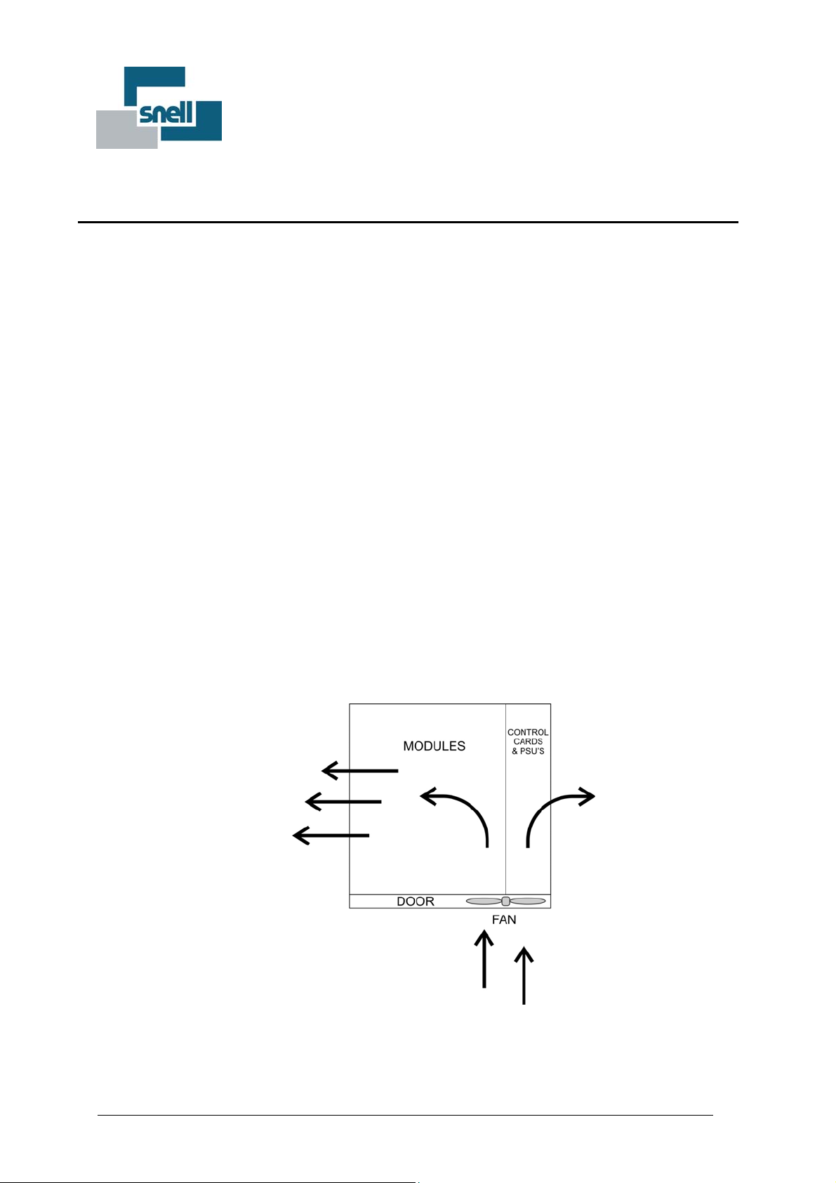
3.1.2 Ventilation
Figure 2: 3U Frame Air Flow
The 3U Pyxis frame ventilation system uses a powerful fan, which is mounted in the front door. The
fan draws air in from the front, circulates it through-out the router, finally passing out through the side
vents. It is therefore important not to block the side air vents. The ventilation flow relies on the front
Issue 2.3 11
PYXIS
System User Guide
door being closed. Do not operate the router for extended times with the door open.
3.1.3 Before Switch-On.
Before you switch-on, check the following items:-
a. Check the correct fuse has been fitted.
b. If a dual power supply is fitted, there will be two mains IEC sockets requiring two power cords (3U
only).
c. Ensure the power modules are firmly in place.
d. Check all other modules are in place.
e. Ensure adequate ventilation.
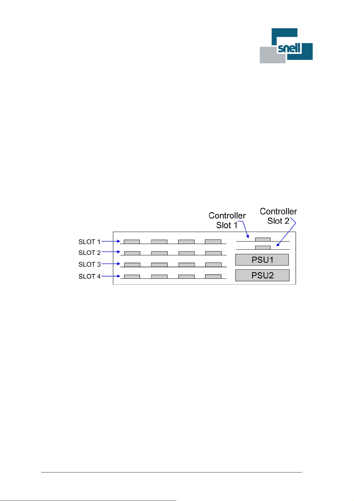
3.1.4 3U Frame Layout
Figure 3: 3U Frame - Layout
The 3U Pyxis frame has four horizontal slots for signal modules.
It also has two slots for power supplies, the frame can run from one but the second provides
redundancy in case of power supply failure.
Above the PSU’s are two slots for controllers, the unit only needs one ‘MASTER’ or ‘ACTIVE’
controller the other slot is for a ‘SLAVE’ or ‘IDLE’ controller there to provide redundancy if the active
controller fails.
Access to PSU2 or Slot 4 requires the door to be removed.
3.1.5 Fitting and removing the frame door
To remove the door from the frame, open it to approximately 30and lift upwards. The design of the hinge
assembly prevents the door from being removed if it is at a greater angle.

HU-PYXIS 12
PYXIS
System User Guide
Figure 4: Removing the front door
For correct fitting of the door, hold the door at approximately 30from the front of the frame ensuring that
it is centrally located above the hinge. The door can then be placed on the hinge and then closed.
For correct cooling, the door must be fitted and closed except when access to the modules is required.
Retaining
Bracket
Scr ews
Card Retaining
Bracket
Card Retaining Strip
Figure 5: Card Retainer (3U)
The Pyxis 3U frame is shipped with a card retaining bracket and card retaining strip fitted. These hold the
modules, PSUs and Controllers firmly in place during transit.
The card retaining bracket and card retaining strip must be removed before power is connected to the
router. To remove the card retaining bracket unscrew the two captive thumb screws and lift clear of the
frame. Also remove the card retainer strip (one for each module). Retain the brackets and fittings for use if
the router is shipped at a later date.
3.1.6 Inserting and removing modules
It is not necessary to power down the frame when inserting or removing system modules as they have
been designed so that they can be ‘hot-plugged’ with the system powered.
The modules locate and lock in place using slot guides in the metalwork and plug into connectors
attached to the rear connector assembly.
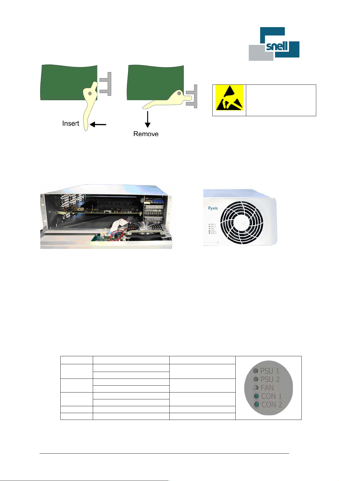
Each module has two handles to allow removal and insertion. Figure 6 shows the right hand handle and
how it locks into the guides in the frame metalwork.
To remove a module, lift up the card ejector on the module and gently pull the card out.
If a card has a board reset switch, it is wise to exercise this after plugging a board in with the power on.
Issue 2.3 13
PYXIS
System User Guide
Electrostatic Damage
Static precautions must be
observed when inserting
and removing all system
modules
Figure 6: Removing Modules
3.1.6.1 3U Fan Module (1945)
Figure 7: 3U Fan Module
The 1945 3U Fan Module and 119mm fan are mounted in the door of the Pyxis frame.
The Fan Module controls and monitors the fan in addition to driving the door status LEDs.
A ribbon cable from the motherboard provides power to the 1945 fan module, which supplies power to
the fans.
The 1945 fan module monitors the status of the fans and provides a combined error signal back to the
controllers
The 1945 fan module is fitted with the following LEDs:-
LED Function Source
PSU1 Green = PSU 1 OK PSU Module
Red = PSU 1 Failure
PSU2 Green = PSU 2 OK PSU Module
Red = PSU 1 Failure
FAN Green = fans OK 1945 Fan Module
Red = fan failure
CON1 Green = controller active Controller 1
CON2 Green = controller active Controller 2
Table 4: Front Door LEDs (3U)
HU-PYXIS 14
PYXIS
System User Guide
A fault signal is available from the fan module relay that can be used within the system as an alarm.
Accessed using the AES/LTC 9-way on the rear panel. See Section 5.1.5 for pin-out details. Details
of setting up the relay are in section 3.1.7.2
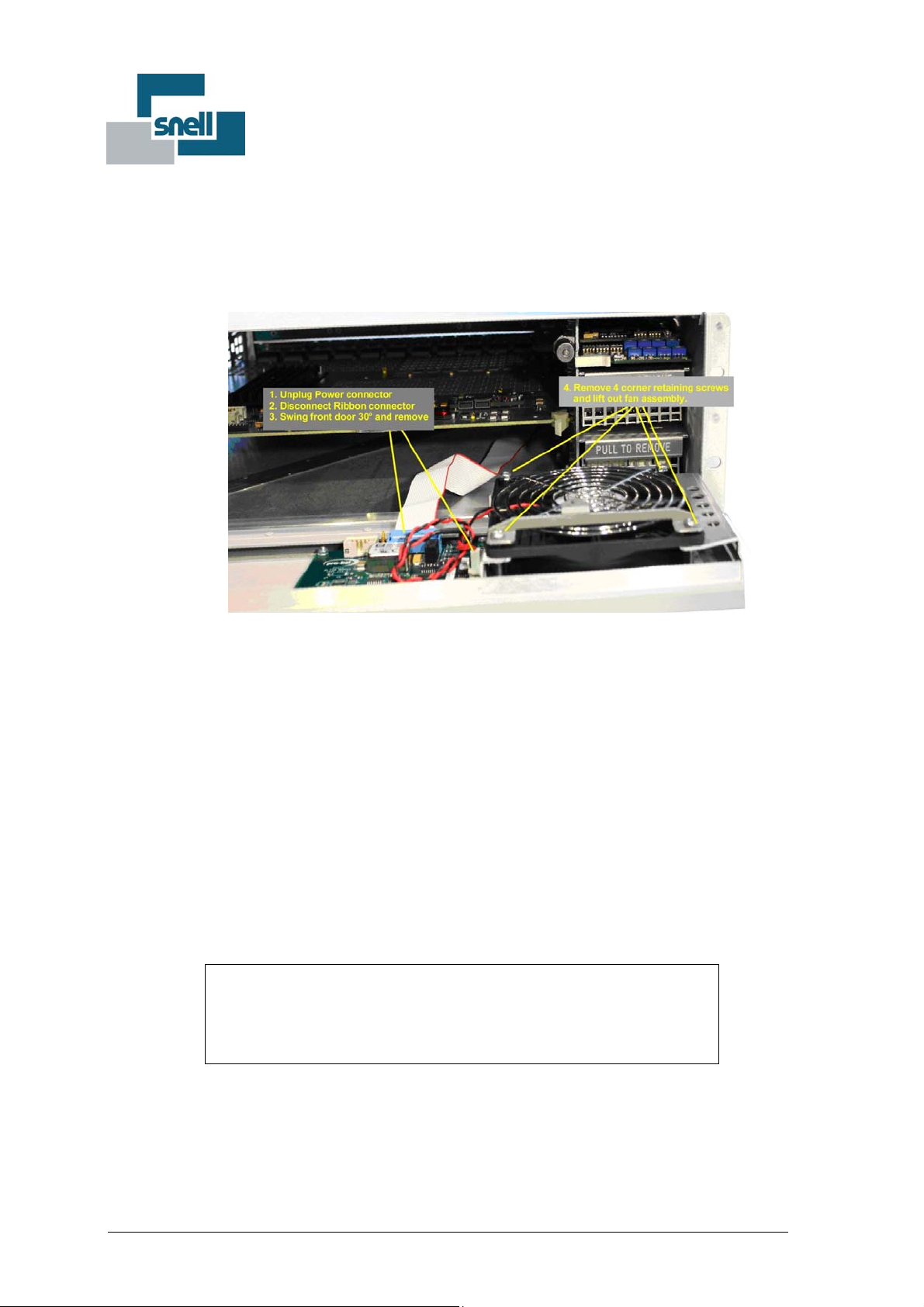
3.1.6.2 Replacing the Fan
Figure 8: Replacing a Fan Module
The Fan Module (fan & PCB) is designed for easy replacement.
To replace the fan:-
1. Unplug the power connector. Do not remove the connector or desolder leads. The replacement
assembly comes with a pre-fitted cable and plug.
2. Disconnect the Ribbon Connector.
3. Swing the front door open 30 degrees and remove from the frame.
4. Remove the four corner retaining screws.
5. Remove and replace the fan.
WARNING
Do not operate the frame for long periods without the fan running
and the door closed. High risk of overheating and damage
Issue 2.3 15
PYXIS
System User Guide
3.1.7 3U Power Supply Modules
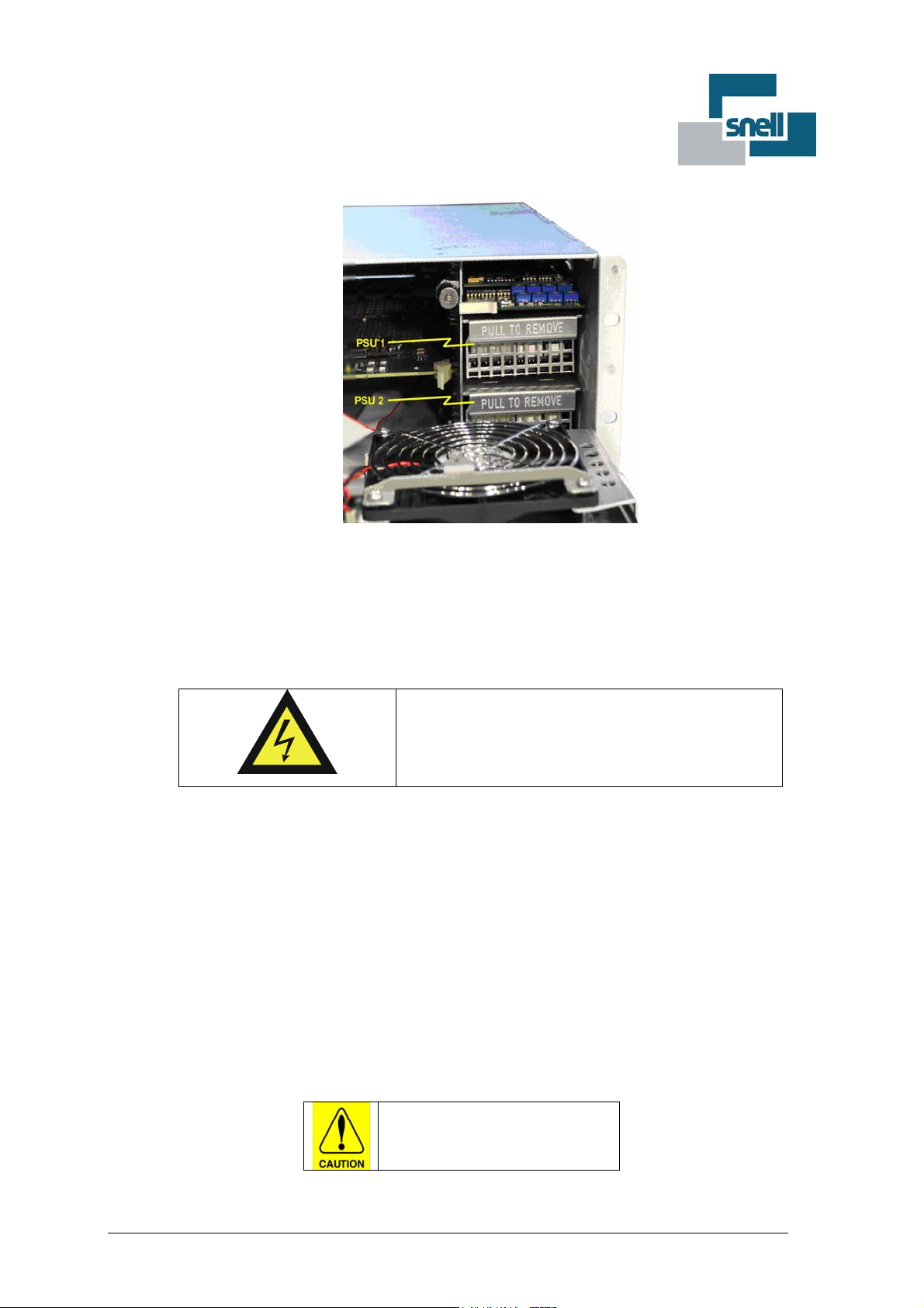
Figure 9: Power Supply (3U)
The power supply slots are on the right hand side of the frame. The Pyxis frame can run from a single
supply but fitting a second provides full redundancy. Each power supply has a 240Watt rating. If both
supplies are fitted they are always live and are electrically arranged to share the load. Each has an
independent IEC mains connector. Each IEC socket is fitted with a fuse which should always be replaced
with the same type.. Each socket also contains a spare fuse.
The power supplies are sealed units.
They do not contain any serviceable items.
HIGH VOLTAGE
The units are hot swappable.
Please read the safety warnings here and on the labels.
The PSU LEDs are mounted on the router front door and will show green if okay or red if failed.
3.1.7.1 Replacing a Power Supply
The Pyxis Power supplies can easily be replaced.
Pull the power supply forward using the handle. Support the weight of the supply and be aware the unit
may still be hot.
The front door of the frame must be removed to gain access to the second PSU
Power Supplies
May be still hot

HU-PYXIS 16
PYXIS
System User Guide
3.1.7.2 Alarm Relay Trigger Enable
Figure 10: Alarm Relay Trigger Enable
Alarm Relay Trigger, accessible via the AES/LTC & RELAY connector on the rear panel can be set
for PSU1, PSU2, and the Fan; they are individually enabled by setting Switches of SW1 on the 1945
Fan Module (fitted to the 3U Frame door) to the ‘ON’ position. The relay operation is the sum of all
the enabled switches.
Switch 1-1 is the enable for PSU1 position
Switch 1-2 is the enable for PSU2 position.
Switch 1-3 enable for the fan alarm
See section 5.1.5 for details of the 9-Way Pin out for connection to the Relay signals.
NOTE: Settings should match your frame configuration, for example, if you only have one PSU fitted
in the PSU2 position then you should set switch 1-1 to ‘OFF’to disable the empty PSU1 slot
generating a false alarm trigger.

Issue 2.3 17
PYXIS
System User Guide
3.2 1U
3.2.1 Ventilation
Figure 11: 1U Air Flow
The 1U Pyxis frame ventilation system uses three small fans mounted in the front door. The fans
draw air in from the front circulate it throughout the router, finally passing out through the side vents.
It is therefore important not to block the side air vents. The ventilation flow relies on the front door
being closed. Do not operate the router for extended times with the door open.
3.2.2 Internal Layout
Figure 12: 1U Frame Layout
The 1U frame has a single slot allowing one routing module to be fitted.
Power is supplied from two external PSUs, which are diode-or’d on the motherboard to
provide dual redundancy
Cooling is provided by fans mounted in the front door
Signal cards and rear panels are common to both the 3U and 1U frames.
HU-PYXIS 18
PYXIS
System User Guide
3.2.2.1 The 1U Fan Module (1946)
The 1946 1U Fan Module mounts on the door of the 1U frame. The Fan Module provides monitoring
of the fans fitted on the door, and also carries the status LEDs that show through the door.
A ribbon cable from the motherboard provides power to the 1946 Fan Module. The 1946 supplies
power to the fans on the door, monitors the status of the fans and provides a combined error signal
back to the controller. An LED on the door also reflects the fan status. The 1946 fan module is fitted
with the following LEDs which are visible through the door.
LED Function Source
Power 1 OK Green = PSU 1 OK 9005 1U motherboard
Power 2 OK Green = PSU 2 OK 9005 1U motherboard
Fans OK Green = fans OK
Red = fan failure
1946 fan module
Table 5: Front Door LEDs (1U)
3.2.3 1U Power Supply
The 1U frame uses an external power supply unit. They are non-repairable units with no internal
serviceable items. A second PSU may be fitted for redundancy.
The power supplies contain dangerous high voltages.
There are no serviceable items.
Issue 2.3 19
PYXIS
System User Guide
4 Control Options
A Pyxis router supports a variety of Snell control systems; Nebula, Aurora and Workbench. Nebula
and Aurora combine to make up the legacy control system and Workbench the next generation with
enhanced features and user front end. The control system defines which control card must be used
within the Pyxis frame.
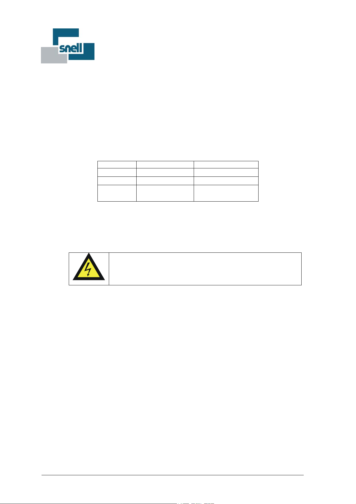
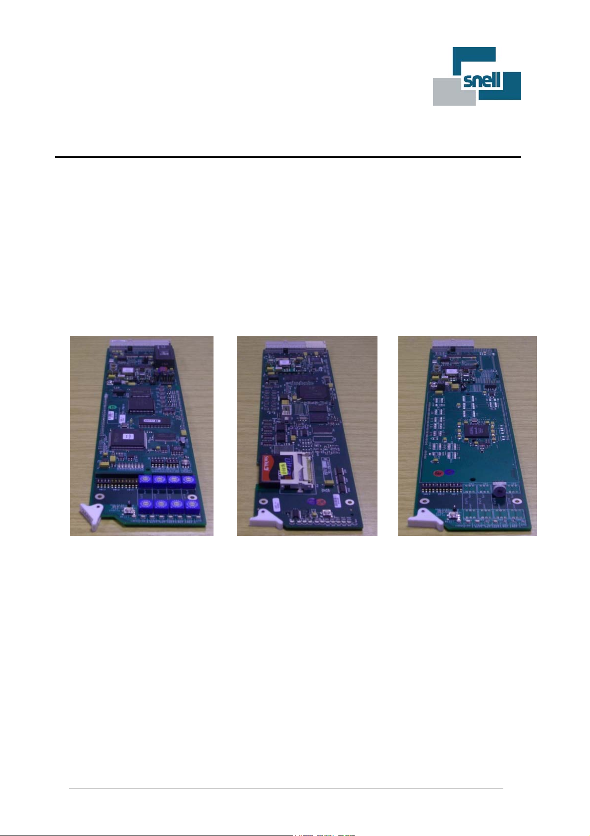
The 2449 allows control with Nebula and/or Aurora
The 2450 allows control with Workbench or Aurora.
The 2451 is a slave frame controller and used in Slave Frames of expanded systems (refer
to section 5.1.9 for details of expansion set up)
2449 2450 2451
Figure 13: Pyxis Control Card Options
4.1 Dual Redundant Controller Operation
Failure of a router controller will not lose signal connections through the router, but can render a
system inoperable. The 3U Pyxis frame allows dual redundant control modules to be fitted, meaning
a fully redundant control system is available, where changeover is both transparent and immediate.
When two control modules are fitted one must be designated ‘Master’ and the other as ‘Slave’. This
is set using switches on the Nebula controller and in software for the Nucleus controller. See the next
section of this manual.
In a dual control system one controller will always be ‘ACTIVE’ while the other is ‘IDLE’. In the event
of the ‘ACTIVE’ controller failing, the ‘IDLE’ controller will take over control of the frame and become
‘ACTIVE’.

HU-PYXIS 20
PYXIS
System User Guide
On power up, the control module designated MASTER will become ‘ACTIVE’. Every main loop, the
software checks whether a changeover has occurred. When a controller changes state from ‘IDLE’ to
‘ACTIVE’ a message is issued to the remote control ports, such that any external control system,
such as Aurora, will be able to report the change.
All data is synchronized constantly between the dual controllers, using an internal serial link. This
data includes the tally table, configuration and database, ensuring that in the event of a controller
changeover no crosspoint routes change and all configuration parameters remain the same. Since all
control ports and reference signals connect only to the active controller, using tri-state drivers, a
controller changeover will be transparent to the user.
A controller changeover may be forced by the user by either pressing the reset button on the active
controller, or removing the active controller.
In the event of a second controller, configured as a slave, being plugged into a single controller
system, all data is automatically transferred from the active controller over a period of time.
Do not press the reset on the ACTIVE control module or remove the ACTIVE module after
plugging in the IDLE controller. It takes up to ten minutes to download the database. If the
reset is pressed during this time ALL DATABASE SETTINGS WILL BE LOST, and the default
database and tally table loaded.
4.2 2449: Nebula Controller
The Pyxis router is supplied with a basic database and default settings for all control ports. This
means external controllers, control panels and Under Monitor Displays can be directly connected to
the frame if required. The database contains system configuration details such as the number of
logical/control levels within the system, signal types and control panel functions.
4.2.1 Functionality
The 2449 is a microprocessor-based module made up of a base card and 2445 Nebula Card.
Together they run system code from flash memory giving a rapid boot-up and easy code upgrade.
NVRAM on the module holds a record of the system crosspoint settings (known as the 'tally table')
ensuring that the router status is maintained following power interruptions or signal module removal.
The system database and an exact record of the router module hardware, known as the
'configuration' are also held in memory on the module.
The control module(s) connect to all router signal modules within the frame via a serial control bus
(routed on the system Motherboard). Status data from the PSU(s) and Fan Module is passed onto
the controller(s) via dedicated logic lines.
All external communication is passed through the control module(s) whether for remote control of the
router or connection of control panels or Under Monitor Displays.
The final function performed by the controller(s) is to detect and process the audio and video
Table of contents
Other Snell Speakers manuals


