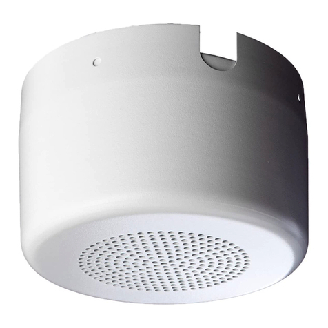
Snell SR.5 Surround User manual

SR.5
Surround Speaker System
Owner’s Manual

2
INTRODUCTION
We designed the SR.5 for maximum placement flexibility.
You can mount the SR.5’s virtually anywhere around your
listening room and still achieve strong envelopment. The
SR.5’s use a unique bipolar radiating pattern for dozens
of unique placement options.
fiOn side walls
fiOn back walls
fiOn the ceiling
Most importantly, the SR.5’s do not require symmetrical
placement. You can place one unit on a side wall, and the
other on the ceiling or back wall.
For Use With All Home Theater Formats
The SR.5’s meet the demanding sonic requirements of
digital 5.1 formats.
fiTheir dispersion pattern combines an
optimal blend of diffuse sound, with just
enough directivity for precise off-screen pans.
fiThey extend from 70 to 20,000Hz, capturing all
surround information in this range.
fiThey play loud enough to fill a typical
listening room at theater volume.
fiTheir power response matches the Snell K.5
Monitors and E.5 Towers for seamless front-to-
back pans.
SPECIFICATIONS
Specifications SR.5 Surround
Usable Frequency Range 70–20,000Hz
Power Response (±3dB) 90–12,000Hz
Recommended Amplifier Power 20–150 watts
Nominal Impedance 8 ohms
Sensitivity 90dB [1 watt (2.83v) at 1m]
speaker in half space, wall-mounted
High Frequency Drivers Dual subenclosed 3 1¼2" (89mm) extended-range units
with copolymer cones
Bass Unit 5 1¼4" (135mm) omnidirectional unit with cast-alu-
minum basket, copolymer cone, and butyl rubber surround
Crossover Frequency 400Hz
Cabinet Construction High density fiberboard
Grilles Friction fit cloth grilles on an MDF frame
Flush Mounting Bracket Positive-click locking mounting bracket for wall or ceiling
Included Hardware Four (4) 3" #10 machine screws with toggle wings
Four (4) 2" #8 particleboard screws
Eight (8) felt bumpers
Dimensions (HxWxD) 13.75" x 6.75" x 7.5" (343mm x 168mm x 187mm)
Weight/each 12 lbs. (5.5kg)
Finish Hand-sanded, hand-painted Black or White paint

3
FEATURES OF THE SNELL SR.5 SURROUND
Mounts to Walls or Ceilings
Our unique locking bracket keeps the SR.5 securely
mounted to walls or ceilings. One person can install
the SR.5 simply and securely.
Connectors
Five-way gold-plated binding posts allow quick con-
nection to speaker cables and connectors. The
recessed area on the back of the cabinet accommo-
dates wire slack for neat installation.
Hand-Tuned Crossover
The bipolar network is optimized to provide a smooth
and flat power response. Each crossover is tuned by
our technicians to ±0.5dB of the Master Reference,
assuring predictable performance in your home.
Angled Cabinet Design
The angled cabinet of the SR.5 projects sound for-
ward and backward in a “dog-bone” pattern. This wide
sound field gives you dozens of placement options.
Speaker Elements
Two 3 1¼2" (89mm) extended-range drivers are
responsible for frequencies between 400Hz and
20kHz. One omnidirectional 5 1¼4" (135mm) bass
unit handles all frequencies from 70Hz to 400Hz.
Family Sound
The SR.5’s are tuned with a flat, optimized power
response, to match the spectral balance of Snell front
speakers.
1
2
2
2
4
5
6
1
2
3
4
5
6

4
5' (1.8m) Max.
12" (30cm) Min.
5' (1.8m)
Max.
12"
(30cm)
Min.
12" (30cm) Min.
5' (1.8m) Max.
Place the SR.5 to the side of the listening area. If the listening area
is against a wall (for example, if your couch is placed against a back
wall), place the SR.5 to the side of the couch, leaving at least a 12"
clearance between the SR.5 and the back wall.
When placing the surround behind your listening area, keep it as
close to the side wall as possible—but no closer than 12" (30cm).
HOW TO PLACE YOUR SR.5 SURROUNDS
Side Wall Placement Back Wall Placement
Determine Room Placement
Proper room placement is perhaps the most important factor contributing to home the-
ater sound quality. Take a few minutes to place your speaker systems correctly to ensure
they sound their best.
Home Listening Room Placement
Follow these guidelines for proper placement:
Height: Place the surrounds at least 5' (2.4m) from the floor, yet 12" (30cm) from the
ceiling. Higher is better.
Boundaries: Keep the surrounds at least 12” (30cm) away from an adjacent wall or
large obstacle.
Placement Options: Each surround can be placed independently to accommodate your
room. The following diagrams illustrate these placement options:
fiOn side walls fiOn back walls fiOn the ceiling
Screening Room Placement
Snell speaker systems are often used in professional dubbing studios. Follow these
recommendations for critical screening room applications:
Height: At least 8' (2.4m) from the floor, or 18" (46cm) down from the ceiling.
Placement: On the side walls, centered to the listening area.
Boundaries: At least 3' (1m) from back walls.
Coverage Area: Use one surround speaker system for every 3 rows of seats
(approximately 10' between surround speakers).

5
left
speaker
center
speaker
right
speaker
left
SR.5
right
SR.5
left center right
left
surround
right
surround
12" (30cm)
Min.
12" (30cm) Min.
5' (1.8m) Max.
12" (30cm)
Min.
5' (1.8m)
Max.
12"
(30cm)
Min.
5'
(1.8m)
Max.
One or both surrounds may be placed on the ceiling. If the viewing area is in or near a corner, the SR.5’s may be placed
to either side on the adjacent wall or ceiling.
Connecting with Bare Wire:
Insert bare wire into holes and tighten.
Connecting with Banana Plugs, Spade Lugs, or Pins:
The binding posts accept standard banana plugs and pins,
and can accommodate spade lugs up to 5¼16".
Connecting to a Surround Processor
Select the SMALL or NORMAL surround setting on your receiver or processor. This routes
all bass information (typically below 120Hz) from the surrounds to your subwoofer.
Match the Sound Levels of Each Speaker
Your home theater system most likely includes a test signal that simplifies level match-
ing. Refer to the instructions provided with your surround sound electronics.
Receiver or Amplifier
Warning! To prevent
electrical shock, always
switch off the amplifier
or receiver when making
connections to the
speaker system.
Ceiling Placement Corner Placement
CONNECTING THE SURROUNDS

6
WALL OR CEILING MOUNTING YOUR SR.5 SURROUNDS
Please Note:
Installation of surround speakers requires a thorough understanding of construction tools and procedures. We recom-
mend you consult a knowledgeable installer if you are unsure of the physical properties behind your wall or ceiling.
Mounting the Bracket When Using the Machine
Screws and Toggle Wings
1. Drill two 9¼16" (13mm) holes using the bracket as a
template. If running wires behind the wall, make a hole
for them as well.
2. Insert the machine screws through the bracket and
thread onto the toggle wings before penetrating the wall.
3. Level the bracket and tighten the screws.
4. Connect the wires.
5. Place the SR.5 on the bracket and slide down until you
hear a locking “click.”
3" #10 machine bolts
toggle wings
Drill two 9¼16" (13mm)
holes for the toggle wings.
Wires connect to terminals on
back of SR.5. Tuck excess
wire into the recess on back
of the speaker.
Level the bracket before
hanging the speaker.
Place the SR.5 on the
bracket and slide down until
you hear a locking “click.”
Place felt bumpers on back
of the SR.5 to protect your
wall or ceiling.
Mounting on Drywall, Paneling, or Other Hollow
Surfaces
Use the supplied 3" #10 machine screws and toggle wings.
The toggle wings require a 9¼16" (13mm) hole.
Mounting on Wood and Other Solid Surfaces
Use the supplied 2" #8 particleboard screws.
Mounting on Masonry, Adobe, and Similar Surfaces
Consult a knowledgeable installer about proper hardware.
You will obtain best results with #8 screws.

7
LISTENING LEVELS AND
POWER HANDLING
The power recommendation for the system assumes you
will operate the amplifier in a way that will not produce
distortion. All speakers can be damaged by a modest
amplifier if it is producing distortion. If you hear a gritty
noise or other signs of strain, turn down the volume.
Prolonged or repeated operation of your speakers with a
distorted signal can cause damage that is not covered by
the warranty.
HOW TO CARE FOR
YOUR SR.5’S
Cabinet
Your speaker system has been hand-sanded and finished
with either a black or white paint.
fiUse a soft terry cloth towel slightly dampened
with water or a mild detergent. The towel should
be just damp enough to wipe the surface clean
without leaving a trail of moisture.
fiDo not use abrasive cleaners or any cleaner con-
taining chemicals harsher than those found in
glass cleaner.
Grille Cloth
fiYou can remove the grilles from the speaker sys-
tem and gently vacuum to remove dust.
When ceiling mounting, follow the same installation
procedures as previously outlined.
Place felt bumpers on
back of the SR.5 to
protect your ceiling.

143 Essex Street
Haverhill, MA 01832
978-373-6114 phone
978-373-6172 fax
©1998 Snell Acoustics. All rights reserved.
Specifications are subject to change without notice.
542-0003
LIMITED WARRANTY
For five years from the date of purchase, Snell Acoustics will repair for the original owner any defect in materials or
workmanship that occurs in normal use of the SR.5 Surround, without charge for parts and labor.
Your responsibilities are to use the product according to the instructions supplied, to provide safe and secure trans-
portation to an authorized Snell Acoustics service representative, and to present proof of purchase from an authorized
Snell dealer in the form of your sales slip when requesting service.
Excluded from this warranty is damage that results from abuse, misuse, accidents, shipping, repairs, or modifications by
anyone other than an authorized Snell Acoustics service representative. This warranty is void if the serial number has
been removed or defaced.
This warranty gives you specific legal rights, and you may also have other rights that vary from state to state.
If Service Seems Necessary
Contact the dealer from whom you purchased the speaker systems. If that is not possible, call us at 978-373-6114,
or write to:
Snell Acoustics
143 Essex Street
Haverhill, MA 01832
We will promptly advise you of what action to take. If it is necessary to return your speaker system to the factory,
please ship it prepaid. After it has been repaired, we will return it freight prepaid in the U.S. or Canada.
Table of contents
Other Snell Speakers manuals
Snell
Snell XA60 User manual

Snell
Snell IW-T7 User manual
Snell
Snell ICS 570 User manual
Snell
Snell QBx 20 Monitor User manual
Snell
Snell 650r User manual
Snell
Snell 730 770 830 870 User manual
Snell
Snell SR7 Series 7 User manual
Snell
Snell ICS 1030 User manual

Snell
Snell XA 55cr User manual
Snell
Snell SR7 User manual
