Snell CLS.5 User manual

CLS.5
CLS.5
Owner’s Manual
2
Specifications CLS.5
Frequency Response (±2dB) 80Hz–20kHz, -6dB @ 60Hz
Recommended Amplifier Power 15–150 watts (above 80Hz)
Nominal Impedance 8 ohms
Sensitivity [1 watt (2.83v) at 1m] 89dB SPL
Tweeter (video-shielded) 1-inch (25mm) black-anodized aluminum dome
with neodymium magnet structure
Bass Unit (video-shielded) 51¼4-inch (135mm) cast aluminum basket.
Copolymer cone and butyl rubber surround resist
environmental extremes.
Grille Perforated aluminum (47% open), powder-coated
paint
Dimensions (HxWxD) 101¼2x 65¼16 x 81¼16"
26.7cm x 16cm x 20.5cm
Weight/each 11 lbs (5kg)
Finish Black or white powder-coated paint
SPECIFICATIONS
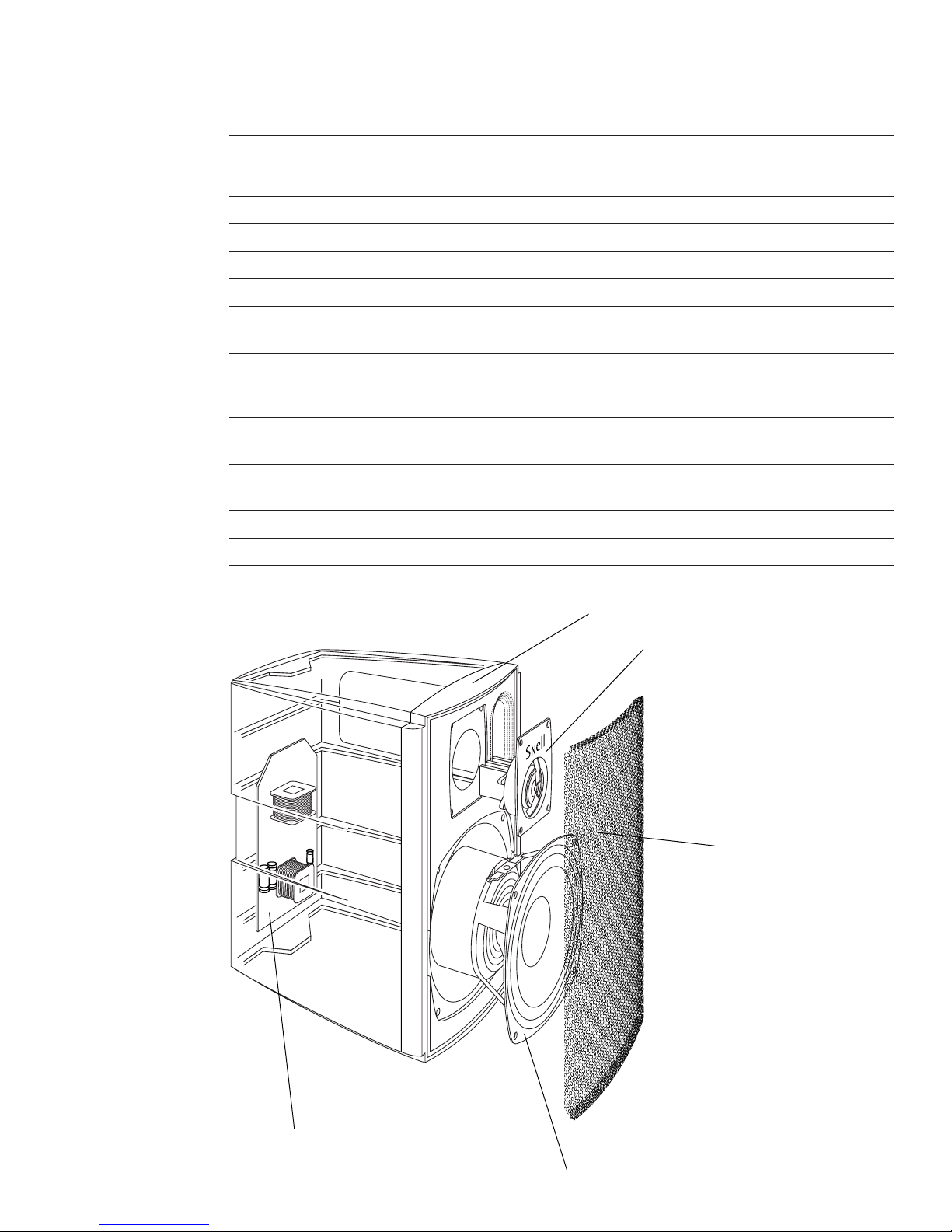
Aluminum die-cast enclosure
51¼4-inch video-shielded bass unit
Hand-tuned crossover
1-inch neodymium magnet tweeter
Highly open perforated
metal grille

3
PRODUCT DESCRIPTION
The CLS.5 is a high-performance die-cast monitor
loudspeaker for use wherever space is limited and
in a wide variety of applications. The CLS.5 is a
two-way design with a complex crossover for best
sound quality. This two-way monitor uses a 1-inch
black-anodized aluminum dome tweeter and a
51¼4-inch bass unit. Both are video-shielded for
placement near a TV. An extremely rigid and heavy
die-cast aluminum enclosure contributes minimally
to the CLS.5’s sound.
The CLS.5 is ideal for use as:
fiAll channels of a surround system where space
is limited.
fiThe front stereo pair of a compact music
system.
fi A multiroom extension speaker.
fi A wall-mounted surround of a larger home
theater system.
fi An extension speaker in environments that
need its weather-resistant characteristics.
Grille Design
The grille is made of perforated metal with a high
percentage of open areas to minimally affect high
frequency performance.
Enclosure Shape
Besides exhibiting distinctive styling, the enclosure
uses careful design to maximize performance.
Specifically, the bass reflex port tube is carefully
flared at both ends to minimize wind noise. The
area surrounding the tweeter is smooth with
minimal recesses to maintain a smooth and trans-
parent high frequency response.
Hand-Tuned Crossover
These networks adhere to an “in-phase” or
Linkwitz-Reilly design (time alignment and
coherency are achieved through the transition
region from driver to driver.) Each crossover
is individually tuned by production technicians to
within ±0.5dB of the Master Reference, assuring
predictable performance in your home.
Heat Sink/Terminal Plate
Heat-producing crossover components are mounted
to a die-cast aluminum heat sink for stable, consis-
tent performance at high power. This large heat sink
also draws heat from inside the cabinet, keeping
critical driver components cooler. The tweeter has its
own multifinned aluminum heat sink.
Video-Shielded
Video-shielded driver complement provides unlim-
ited placement options.

4
Stereo Image
The distance between the speakers determines the
width of the stereo image. If the speakers are
placed too close together, the image will be too
narrow; too far apart and the blend will suffer,
creating a hole in the middle. When properly
placed, your speakers will create a continuum of
“virtual images” from left to right, with an illusion
of sound outside, in front, and behind the
speaker systems.
fi We recommend an angular separation between
45 and 60 degrees (when viewed from above).
This is equivalent to a separation between the
speaker systems that is about 85% to 100% of
the distance to either of the speakers.
fi Aim the center of the speaker to your ear level
while listening in a seated position.
Creation of sounds between the speakers requires
precise placement. The distance from the left
speaker to the listener location should equal the
distance from the right speaker to the listener
location. We advise using a tape measure to equal-
ize these two distances to the primary listening
position. The payoff will be well worth the time
and effort.
Toe In
"Toe in" refers to the angling of the speaker sys-
tems toward the listening location. Toe in is a mat-
ter of taste. As the degree of toe in increases, the
stereo effect becomes more direct-sounding, like a
pair of headphones. Wider angling will give a more
diffuse sound with perhaps a less well-defined
central image. Use the pivoting bracket to experi-
ment for the best effect.
Location Affects Bass Level
Close proximity to rigid wall, floor, and ceiling
boundaries will accentuate the bass level, but may
cause uneven bass. Experiment until you find the
best overall sound for your room. Choose a source
with a heavy and continuous bass line, repeat a
short section until you have a firm impression of it
in your mind, and then try another speaker loca-
tion. Repeat this process until you are content with
the bass response you are getting. Moving your
listening position may affect the sound as much as
moving the speakers. Try different listener locations
as well as speaker locations.
fi Try the speakers at the intended location before
permanent mounting.
fi Moving speakers nearer to a wall increases bass
level.
fi Moving speakers toward a corner will increase
bass level even more.
fi Bass response is smoother if you keep the dis-
tance from the back wall and the distance from
the side wall different.
fi The CLS.5 was designed to have the optimum
balance when close to one boundary surface.
HOW TO PLACE YOUR SPEAKER SYSTEMS
45 deg
60 deg

5
HOW TO MOUNT YOUR CLS.5 LOUDSPEAKER
Bookshelf Mounting
For shelf mounting, use the enclosed conical feet.
The feet are rubber-tipped to absorb vibration and
to prevent marring your shelves. The feet can be
used to tilt the system forward or backward if
needed. For example, using two feet at the front
and no back feet will tilt the system upward
approximately 10 degrees. Two feet at the back and
none at the front will tilt the system forward
slightly. Bringing the two back feet forward toward
the center line will increase the down tilt (if
mounted on a high shelf). You might try the feet
before permanent mounting. Mount the feet by
peeling back the paper covering over the self-
adhesive pads. Make sure that the area for attach-
ment is clean and dry.
Bracket Mounting
The CLS.5 loudspeaker includes a versatile wall-
mounting bracket. With it, you can aim the system
over a wide range of angles. The bracket slots into
the back of the CLS.5 to preserve its appearance.
Wires can come through the wall and through the
center of the bracket; or if run external to the
wall, can go through small holes at either end of
the bracket.
Note: The design of the bracket allows a wide
swing from perpendicular to the wall to nearly
parallel to the wall in one direction. Before mount-
ing the bracket, make sure that you are using the
proper bracket orientation to allow the system to
swing in the desired direction.
Note: Use the two toggle bolts supplied for
mounting to plaster board. Any smaller inserts will
not be sufficient to hold its weight.
1. Mount the bracket to the wall first and then
mount the speaker to the bracket.
2. Mark the location for drilling through the
bracket’s mounting holes. Then drill two 1¼2-
inch diameter holes.
3. Insert the bolts through the bracket and start
the toggle bolts onto the threads.
4. Pass the wire through the appropriate hole and
then push both toggle bolts through the 1¼2-
inch holes. The toggle bolts will fold up to go
into the hole and then spring back. It may be
easier to tighten the toggle bolts by pulling out-
ward on the bracket while tightening the bolts.
Proceed with care because once the toggle bolts
are inserted into the wall, they will not come
out.
5. Once the bolts are tight, connect the wires and
mount the speaker to the bracket. The supplied
Allen Bolts and hex wrench will hold the speaker
tightly at the desired orientation.
Aftermarket Mounts
A single tapped hole on the back of the system can
be used for any of the available pivoting brackets
that use a 7/16 by 20 thread.

6
When Used As a Center Channel
The center channel keeps dialog or soundtrack
information centered in the listening area.
Therefore, its placement relative to the left and
right speakers is critical.
fi Place the speaker on top of or beneath your TV,
with its front edge as far forward as practical.
Try to keep the front of the speaker flush with
the front of the screen.
fi Use two of the rubber-tipped feet along the
back edge of the loudspeaker to raise it to be
parallel to the TV screen.
fi Try to place all front speakers at approximately
the same height. If possible, have the center
system’s height within 2 feet (60cm) of the
height of your left and right speakers.
fi If you need to place the speaker any higher or
lower, angle it toward ear level.
When Used As a Surround Speaker
Surround speakers play a different roll than front
speakers. With three well-placed front speakers
arrayed over a fairly narrow angular area, we can
achieve a precise aural image both at and between
the speakers. By contrast, the surrounds have the
combined task in that they must create an illusion
of many diffuse sound sources in the vast area
beyond the narrow arc of the front speakers, yet
allow for more directed pans of off-screen objects.
As the best compromise, the surrounds should be
placed to achieve a semidiffuse effect.
fi Mount high and to the sides or rear of the main
listening area.
fi Aim the speakers away from the listeners to
make them less “visible” as the source of
surround sound.
fi Side-mounted speakers can be aimed to bounce
sound off of the ceiling. Rear-mounted
speakers might bounce sound off the back wall
or the ceiling.
fi Use the pivoting bracket to experiment for the
best effect.

7
CONNECTING THE SPEAKERS
Choosing Cable
We recommend 16-gauge cable or thicker for runs
up to 25 feet (8m) and 12-gauge wire or thicker for
longer runs.
Connecting with bare wire:
fi Insert bare wire into holes and tighten.
Connecting with banana plugs, spade lugs, or pins:
fiThe binding posts accept standard banana plugs
and pins, and can accommodate spade lugs up
to 5¼16 inch.
Warning! To prevent electrical shock, always
switch off the amplifier or receiver when making
connections to the speaker system.
Basic Connections
fiWhen making connections, be sure to connect
+to +(red) and —to —(black).
Connecting to a
Surround Processor
When using a powered subwoofer:
fi Select the SMALL or NORMAL setting on your
receiver or processor for your main and center
channels. This routes all bass information
(typically below 120Hz) to your subwoofer.
When not using a powered subwoofer:
fi Select the LARGE setting on your receiver or
processor for your main speakers. This routes all
bass information (typically below 120Hz)
to your main speakers.
Match the sound levels of each speaker:
fi Your home theater system most likely includes a
test signal that simplifies level matching. Refer
to the instructions provided with these electron-
ics.
receiver or amplifier
subwoofer
left
speaker
center
speaker
right
speaker
left
surround
speaker
right
surround
speaker
left center right left
surround
right
surround
subwoofer
out
L
TO
AMP
OUT
R
L
FROM
PREAMP
IN
R

HOW TO CARE FOR YOUR SPEAKERS
LIMITED WARRANTY
fiUse a soft terry cloth towel slightly dampened
with water or a mild detergent. The towel
should be just damp enough to wipe the sur-
face clean without leaving a trail of moisture.
fiDo not use abrasive cleaners or any cleaner
containing chemicals harsher than those found
in glass cleaner.
LISTENING LEVELS AND POWER HANDLING
fiThe power recommendation for the system
assumes you will operate the amplifier in a way
that will not produce distortion. All speakers
can be damaged by a modest amplifier if it is
producing distortion. If you hear a gritty noise
or other signs of strain, turn down the volume.
Prolonged or repeated operation of your
speakers with a distorted signal can cause
damage that is not covered by the warranty.
Especially important with smaller speakers is
that you do not overdrive their bass capability.
Watch for noises such as pops caused by the
music’s bass line. Use of the loudness control
and/or full bass boost at louder volumes is
likely to overdrive the woofer. Use such controls
sparingly.
LIMITED WARRANTY
For five years from the date of purchase, Snell
Acoustics will repair for the original owner any
defect in materials or workmanship that occurs in
normal use of the speaker system, without charge
for parts and labor.
Your responsibilities are to use the product accord-
ing to the instructions supplied, to provide safe and
secure transportation to an authorized Snell
Acoustics service representative, and to present
proof of purchase from an authorized Snell dealer in
the form of your sales slip when requesting service.
Excluded from this warranty is damage that results
from abuse, misuse, accidents, shipping, repairs, or
modifications by anyone other than an authorized
Snell Acoustics service representative. This warran-
ty is void if the serial number has been removed
or defaced.
This warranty gives you specific legal rights, and
you may also have other rights that vary from
state to state.
If Service Seems Necessary
Contact the dealer from whom you purchased the
speaker system. If that is not possible, call us at
978-538-6262, or write to:
Snell Acoustics
300 Jubilee Drive, PO Box 3717
Peabody, MA 01961-3717
We will promptly advise you of what action to
take. If it is necessary to return your speaker sys-
tem to the factory, please ship it prepaid. After it
has been repaired, we will return it freight-prepaid
in the U.S. or Canada.
©2004 Snell Acoustics. All Rights Reserved.
Specifications are subject to change without notice.
Covered by patents issued and or pending.
Part #542-1000
300 Jubilee Drive, PO Box 3717
Peabody, MA 01961-3717
978-538-6262 phone
978-538-6266 fax
Table of contents
Other Snell Speakers manuals

Snell
Snell IC-B7S User manual

Snell
Snell SR.5 Surround User manual

Snell
Snell Illusion A User manual

Snell
Snell PYXIS User manual

Snell
Snell AMC 680 User manual

Snell
Snell ICS 1070 User manual

Snell
Snell ICS570 User manual

Snell
Snell QBx 20 Monitor User manual

Snell
Snell AMC 800 User manual

Snell
Snell OH-S7 User manual


Popular Speakers manuals by other brands

GLEMM
GLEMM AT 24 instruction manual

Atlantic
Atlantic Indoor Furnishings Assembly instructions

Beta Three
Beta Three V122a user manual

Hubbell
Hubbell GAI-Tronics 13310-4 Series Instruction and service manual

Fresh 'N Rebel
Fresh 'N Rebel Rockbox Brick manual

Wharfedale Pro
Wharfedale Pro WLA-210XF instructions


