Snell QB 25 Series User manual

QBx 25 Tower
Owner’s Manual
QBx 25
Tower Speaker System

2
SPECIFICATIONS
Frequency Response (±3dB) 45Hz–20kHz
Recommended Amplifier Power 15–150 watts
Nominal Impedance 4 ohms
Sensitivity (2.83v at 1m) 89dB SPL
Tweeter (video-shielded) 1-inch (25mm) black-anodized aluminum dome
with neodymium magnet structure and multi-
finned aluminum heatsink
Bass Units (video-shielded) 61/2-inch (165mm) polymer chassis, HDA cone and
rubber surround
Cabinet Construction: 3/4-inch MDF walls
Composite Baffle Construction: 5/8-inch high density fiberboard, specialty
adhesive, and 5/8-inch high-density fibreboard
Grille Black cloth
Dimensions (HxWxD) 335/8x 81/2x 10 (855 x 216 x 254 mm)
Shipping Weight 40 lbs. (18 kg) each
Finish Black Oak, Cherry, others to special order
Hand-Tuned
Crossover
6
1
/
2
" Video-Shielded
Bass Units (2)
"Butterfly"
Grille Cutout
Elliptical
Baffle Edges
1" Neodymium
Magnet Tweeter
High Loss
Sandwich Baffle

3
Product Description
The QBx 25 (“Quiet Box”) Tower is a compact and slim floorstanding loudspeaker providing
exceptional performance and value. The QBx 25 features unique cabinet construction, superior
drive units, 21/2way design and a complex crossover, which contribute to its superior sound
quality.
QBx Technology
In an ideal speaker, the speaker cabinet is inert and resonance free. It should have smooth
contours without projections that cause reflections which degrade high frequency response. In
short, the cabinet should not negatively affect the sound of the loudspeaker. QBx (Quiet box)
refers to a number of techniques that reduce the detrimental effects that typically come from
the resonances and reflections of ordinary cabinets.
“Butterfly” grille cutout
The necessary cutout area around the tweeter is given a highly irregular contour to prevent the
irregular high frequency response that would otherwise occur. The contour expands and
contracts around the perimeter of the tweeter, creating a “butterfly” shape.
Elliptical baffle edges
The grille is mounted flush into the baffle. The baffle edges have large elliptical radiuses. This
smooths the cabinet termination, greatly reducing the edge reflections. High frequency
smoothness is preserved.
High-Loss Sandwich Baffle
The unique high loss baffle is constructed from multiple layers of wood and a high tech
adhesive. The “lossy” adhesive that laminates the two layers of speaker baffle greatly reduces
cabinet resonances, resulting in purer midrange and clean, crisp bass.
Hand-Tuned Crossover
The crossover networks were designed using sophisticated computer simulation. Final system
balance is determined by exhaustive listening tests. These networks adhere to an “in-phase” or
Linkwitz-Reilly design: time alignment and coherency are maintained through the transition
region from driver to driver. In production, each crossover is individually tuned by technicians
to within ±0.5dB of the Master Reference, ensuring predictable performance in your home.
Drive Units
This 21/2way tower uses a 1-inch black-anodized aluminum dome tweeter with a multifinned
aluminum heatsink and dual 61/2-inch bass units with High Definition Aerogel cones. The
video-shielded driver complement provides unlimited placement options.

4
Distance Between Speakers
Distance to Listening Area
50°
HOW TO PLACE YOUR SPEAKER SYSTEMS
Speaker Separation
The distance between the speakers determines the width of the stereo image. If the speakers are
placed too close together, the image will be
too narrow; too far apart and the blend will
suffer, creating a hole in the middle. When
properly placed, your speakers will create a
continuum of “virtual images” from left to
right, with an illusion of sound outside, in
front, and behind the speaker systems.
We recommend an angular separation of
about 50 degrees (when viewed from
above). This is equivalent to a separation
between the speaker systems that is about
85% of the distance from the speakers to
the listener location.
Speaker Distance
Creation of sound between the speakers requires precise placement. The left and right speakers
both be the same distance from the listener location. We advise using a tape measure to
equalize these two distances to the primary listening position. The results will be well worth the
time and effort.
Aiming the Speakers
Your Snell speakers are designed to produce a very smooth response over as wide a range of
radiated angles as possible. Like all speakers of this type the response evenness is maintained
over a wider horizontal arc than vertical (assuming the long box dimension is vertical). Take
this into account when placing and aiming your speakers.
Toe-In
“Toe-in” refers to the angling of the speaker systems toward the listener location. Toe-in is a
matter of taste. As the degree of toe-in increases, the stereo effect becomes more direct-
sounding, like a pair of headphones. Speakers not toed-in will give a more diffuse sound with a
less defined central image.
Room-Related Bass Effects
As speakers are moved closer to rigid room boundaries – the walls, the floor, and the ceiling –
the deep bass part of the sound range is accentuated. However, if speakers are too close to the
room boundaries, particularly corners, the bass output can be uneven. Experiment until you
find the best overall sound for your room. Choose a musical selection with a strong, continuous
bass line. Repeat a short section until you have a firm impression of it in your mind, then try
another speaker location. Repeat this process until you are content with the bass response you
are getting. Moving your listening position will affect the sound as much as moving the
speakers. Try different listener locations as well as speaker locations.

5
BOUNDARY EFFECTS
Large surfaces near your speakers will affect the level of upper bass and lower midrange
frequencies. This can make voices sound unnatural. A feature to counteract this is the Bass
Loading switch, with positions for Normal or Boundary. Refer to the switch on the input
terminal plate.
Normal or Freestanding placement refers to a situation in which the XA Tower has at least
a 12 inch (30cm) clearance on all four sides. Set the Bass Loading switch to Normal when the
speaker is:
uAway from large furniture.
uNot close to walls.
Boundary placement refers to a situation in which the XA Tower is bounded on at least one side
by a large object. Set the Bass Loading switch to Boundary when the speaker is:
uPlaced beside a TV.
uPlaced beside a bookshelf or an audio/video cabinet.
uPlaced next to a wall.
Freestanding Boundary
CONNECTING THE SPEAKERS
Warning! To prevent electrical shock, always switch off the amplifier or receiver when making
connections to the speaker system.
Choosing cable
We recommend 16 gauge cable or thicker for runs up to 25 feet (8m) and 12 gauge wire or
thicker for longer runs. (We use a custom-configured 12 gauge oxygen-free cable in our
crossover networks.)
Connecting with bare wire:
Insert bare wire into holes and tighten.
Connecting with banana plugs, pins or spade lugs:
The gold-plated binding posts accept standard banana plugs and pins, and can accommo-
date spade lugs to 5/16-inch.

6
Basic Connections
Keep the speaker terminal jumper straps in
place.
When making connections, be sure to connect
+ to + (red) and – to – (black).
Bi-Wiring
Use equal lengths of the same kind of cable
when bi-wiring each speaker.
Unscrew both sets of terminals and remove
the jumper straps.
When making connections, be sure to connect
+ to + (red) and – to – (black).
QBx 25
amplifier or receiver
speaker terminal
jumper straps
QBx 25
amplifier or receiver
Bi-Amplifying
Using One Amplifier for the Bass
and One for the High End
Unscrew both sets of terminals
and remove the jumper straps.
Connect the cables from the
bottom set of terminals to the
amplifier driving the bass unit.
Connect the cables from the
top set of terminals to the
amplifier driving the tweeters.
When making connections, be
sure to connect + to + (red)
and – to – (black).
Do not use an external
crossover. It will interact with
the phase and frequency
response of the QBx 25.
left speakerright speaker
low frequency amplifier
high frequency amplifier

7
left speakerright speaker
right channel amplifier left channel amplifier
Bi-Amplifying
Using One Amplifier for the Bass and One for the High End
Unscrew both sets
of terminals and
remove the jumper
straps.
Connect the cables
from the bottom
set of terminals to
the amplifier
driving the bass
unit.
Connect the cables
from the top set of
terminals to the
amplifier driving
the tweeters.
When making
connections, be sure to connect + to + (red) and – to – (black).
Do not use an external crossover. It will interact with the phase and frequency response of
the QBx 25.
LISTENING LEVELS AND POWER HANDLING
The power recommendation for the system assumes you will operate the amplifier in a way
that will not produce distortion. All speakers can be damaged by even a modest amplifier
if it is producing distortion. If you hear a gritty noise or other signs of strain, turn down
the volume. Prolonged or repeated operation of your speakers with a distorted signal can
cause damage that is not covered by the warranty. It is especially important that you do
not overdrive the bass capability of smaller speakers. Watch for noises, such as pops,
caused by the music’s bass line. Use of the loudness control and/or full bass boost at
louder volumes is likely to overdrive the woofer. Use such controls sparingly.

©1999 Snell Acoustics. All Rights Reserved.
Specifications are subject to change without notice.
Covered by patents issued and/or pending.
Part #542-1012
143 Essex Street
Haverhill, MA 01832
phone: 978-373-6114
fax: 978-373-6172
email: [email protected]
www.snellacoustics.com
LIMITED WARRANTY
For five years from the date of purchase, Snell Acoustics will repair for the original owner any defect in
materials or workmanship that occurs in normal use of the speaker system, without charge for parts and labor.
Your responsibilities are to use the product according to the instructions supplied, to provide safe and secure
transportation to an authorized Snell Acoustics service representative, and to present proof of purchase from an
authorized Snell dealer in the form of your sales slip when requesting service.
Excluded from this warranty is damage that results from abuse, misuse, accidents, shipping, repairs, or
modifications by anyone other than an authorized Snell Acoustics service representative. This warranty is void if
the serial number has been removed or defaced.
This warranty gives you specific legal rights, and you may also have other rights that vary from state to state.
If Service Seems Necessary
Contact the dealer from whom you purchased the speaker system. If that is not possible, call us at 978-373-
6114, or write to: Snell Acoustics
143 Essex Street
Haverhill, MA 01832
We will promptly advise you of what action to take. If it is necessary to return your speaker system to the
factory, please ship it prepaid in the original factory packaging. Please note that Snell Acoustics will not be held
liable for shipping damage due to improper packaging. After it has been repaired, we will return it freight-
prepaid in the U.S. or Canada.
Table of contents
Other Snell Speakers manuals

Snell
Snell XA 55cr User manual

Snell
Snell A-III User manual
Snell
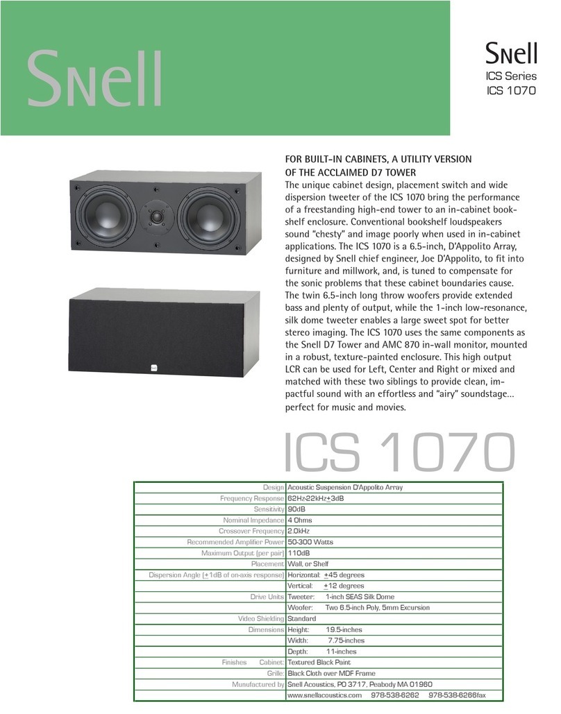
Snell ICS 1070 User manual
Snell
Snell AMC Sub 88 User manual
Snell
Snell AMC 2000 User manual
Snell
Snell J7 User manual
Snell
Snell AMC 870 User manual
Snell
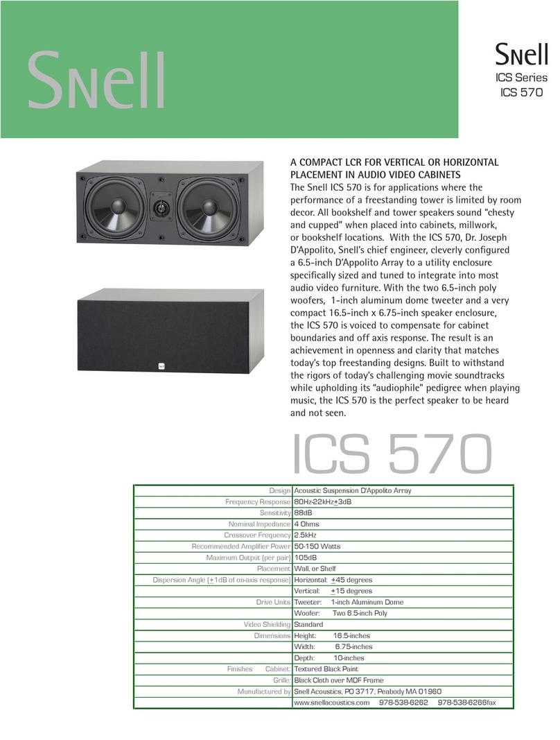
Snell ICS 570 User manual
Snell
Snell XA Series User manual
Snell
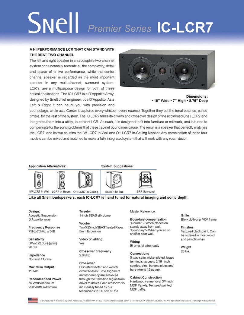
Snell IC-LCR7 User manual
