Snell XA60 User manual

XA60 Tower
Owner’s Manual
XA60

2
SPECIFICATIONS
Frequency Response (±3dB) 36-22,000Hz
Nominal Impedance 4 ohms
Recommended Amplifier Power 100-300 watts
Sensitivity [2.83v at 1m] 89dB SPL
Driver Complement (all video-shielded)
Front Tweeter 1-inch (25mm) black-anodized aluminum with separate PVC surround
Midranges Two 21/2-inch (64mm) mounted in separate enclosure
Woofers Two 8 inch (210mm) with butyl rubber surrounds
Rear Tweeter 1-inch (25mm) fabric dome
Controls Treble level, boundary bass level, boundary rear tweeter
Cabinet Construction Heavily braced, veneered MDF (3/4-inch minimum)
Baffle Construction Rubber isolated, constrained layer damping; low diffraction edge radius
Grille Frameless perforated metal, minimum 51% open area
Maximum Dimensions (HxWxD) 421/4“ x 91/2” x 161/4” (107 x 24 x 41cm)
Net Weight 73 lbs (33kg)
Shipping Weight 80 lbs (36kg)
Finishes Black Oak, Cherry, others to special order

3
INTRODUCTION
The XA60 is a high-performance floorstanding speaker
utilizing a unique expanding array format (XA). This
array was created after several months of intensive
computer modeling and study, with a serious review of
what is appropriate for both music and home theater
usage. With the new XA60 Towers, Snell engineers have
created a three-element array with virtually no change
in response through ±15 degrees vertically, yet a
desirable, significant drop in response at 30 to 45
degrees above or below axis. While there is no detect-
able variation within a likely listening window, there is a
significant reduction in the amount of sound that is
reflected from the floor and ceiling. This reduces the
energy of the reverberant field, resulting in a clearer,
more articulated sound. This design approach is not only
beneficial to the movie lover, but is also much more
appropriate for multichannel music listening with the
latest discrete music formats.
PRODUCT DESCRIPTION
The special three-element XA provides controlled
directivity to 400Hz. The driver complement includes a
1-inch (25mm) black-anodized aluminum dome tweeter
flanked by a pair of 21/2-inch (60mm) upper midranges
mounted on a die-cast aluminum plate. Dual 8 inch
(210mm) woofers, mounted in a sizeable enclosure,
ensure robust, musical bass response to 36Hz (±3dB). A
soft-dome rear-firing tweeter is included for added
ambiance.
The XA60 Towers feature a high degree of environment
tunability. A “boundary” switch ensures smooth bass
response in a variety of room positions. The tweeter level
control switch and rear tweeter on/off switch make it
easy to fine-tune the XA60 to its environment and your
tastes. The system is magnetically shielded for use near
video monitors.
The XA60 also features hand crafted cabinetry; its
stunning styling is fully integrated into its acoustical
function.

4
XA60 FEATURES
Multi-Element Expanding Array
Months of study and computer simulation resulted in a
scientifically designed three-element array with
idealized dispersion characteristics. The XA60’s perfor-
mance is seamless and invariant within any likely
listening position. Controlled directivity beyond normal
vertical angles reduces room involvement, resulting in a
clearer and more detailed image with either movie or
multichannel music sources.
Platform Baffle
This three-layer sandwich isolates the
baffle from the cabinet to decrease panel
resonances and coloration, especially in
the critical midrange. The Platform Baffle
consists of materials of varying density: an
extremely dense outer layer to which the
tweeter and bass units are mounted, a
high loss neoprene middle layer, and a
medium density inner layer that attaches
to the cabinet.
Radiused Edge Baffle
The elliptical radius on our baffle edge
reduces re-radiation for a cleaner and
smoother response. Snell pioneered this
technique in the original Type A speaker
system in 1976.
Rear-Firing Tweeter
The rear-firing tweeter on the XA60 adds
necessary high-end fill to the soundstage,
creating a broader, deeper stereo image.
An on/off switch allows you to defeat the
rear tweeter when the back of the speaker
is close to a wall.
Grille Design
The custom-perforated metal grille has no
frame to cause degrading reflections in
the upper frequencies. Rubber mounts
isolate the grille from the Platform Baffle.
2
1
5
3
6
7
4
1
2
3
4
5

5
Handmade Cabinets
The entire construction and finishing process is done by
hand. Each cabinet is assembled by our craftsmen, then
sanded several times. Multiple coats of hand-applied
finishing oils reveal the great depth of the wood grain.
The result is a cabinet of exceptional workmanship, with
sharp corners, smooth sides, and natural beauty.
Veneers
We use premium book-matched veneers, chosen for
grain consistency and aesthetics, in our cabinets. Each
pair of speakers has wood veneer from the same tree, so
grain patterns are consistent. Our cabinet shop se-
quences the veneer, maintaining a match for the top,
right/left, and left/right sides of each pair of speakers.
We even go so far as to veneer the inside of the cabinet
to ensure that it won’t warp or come apart at the edges
when exposed to changes in humidity.
Hand-Tuned Crossover
These networks adhere to an in-phase or Linkwitz-Reilly
design. (Time alignment and coherency are maintained
through the transition region from driver to driver.) Each
crossover is individually tuned by our production
technicians to within ±0.5dB of the master reference,
ensuring a consistent sound balance and predictable
performance.
Placement Switch
Placement of the system near a boundary, such as a
wall, large cabinet or big-screen television, can alter the
sound balance, making voices sound “bloated”. The Bass
Loading switch lets you compensate for the sonic effects
of such placement. This Snell feature ensures ideal sound
balance in virtually any location.
Heat Sink/Terminal Plate
Heat-producing crossover components are mounted to a
die-cast aluminum heat sink for stable, consistent
performance at high power. This large heat sink also
draws heat from inside the cabinet, keeping critical
driver components cooler. The terminal plate has two
sets of five-way gold-plated binding posts for bi-wiring
or bi-amplifying.
8
9
10
6
7
8
9
10
6
PLACEMENT OF YOUR SPEAKER SYSTEM
The XA60 Towers are designed for either freestanding or
boundary placement.
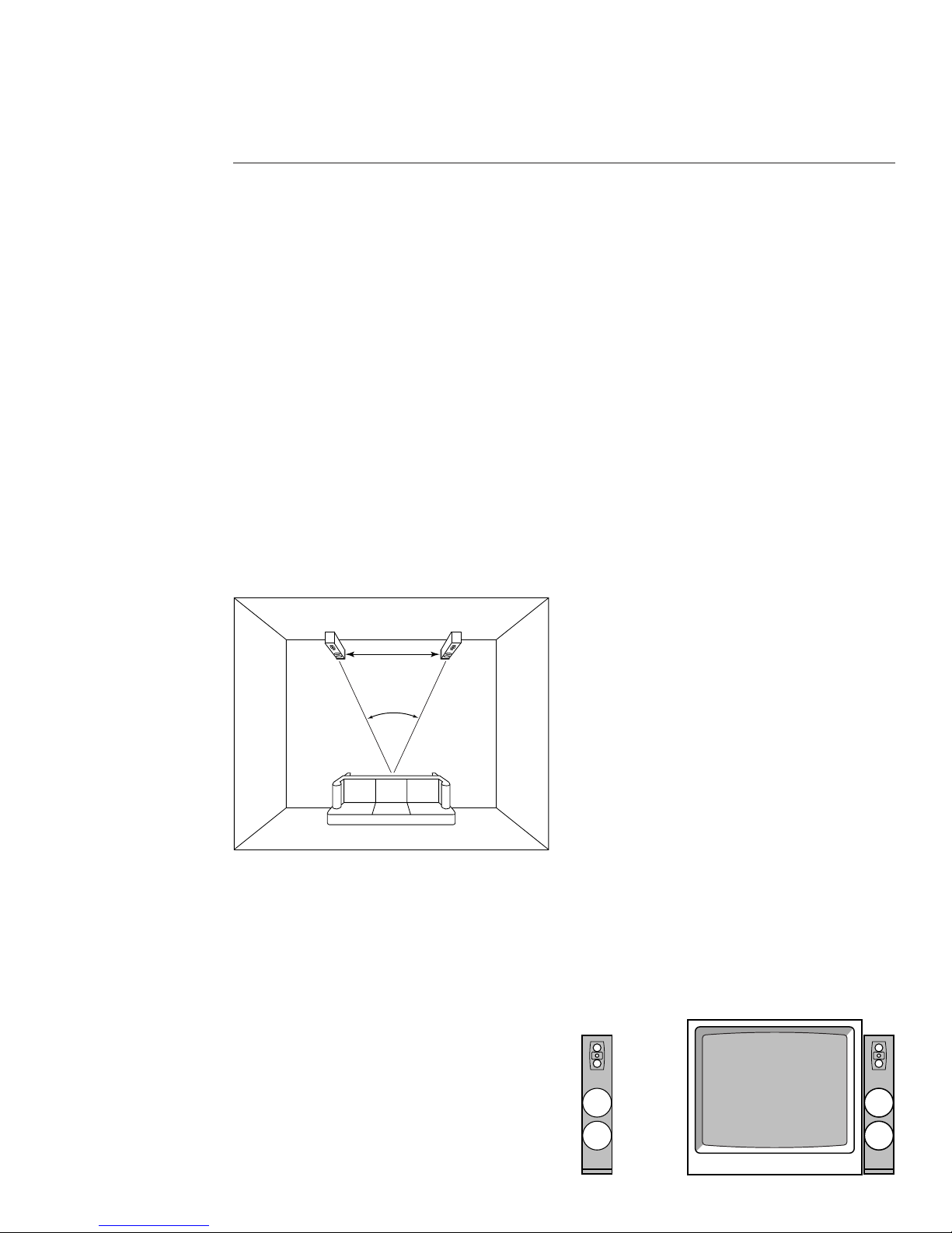
Stereo Image
The distance between the speakers determines the width
of the stereo image. If the speakers are placed too close
together, the image will be too narrow; too far apart
and the blend will suffer, creating a hole in the middle.
When properly placed, your speakers will create a
continuum of virtual images from left to right, with an
illusion of sound outside, in front of, and behind the
speaker systems.
We recommend an angular separation of approximately
50 degrees (when viewed from above). This is equivalent
to a separation between the speaker systems that is
about 85% of the distance to either of the speakers
from the listener location.
Room-Related Bass Effects
Your room dimensions will determine the frequencies of
a phenomenon call “standing waves”. Where the
speakers are placed relative to the stong points and
weak points (anti-nodes and nodes) of these standing
waves significantly effects the bass characteristics of the
system. Experiment until you find the speaker locations
that produce the best overall sound for your room.
Choose a musical selection with a heavy and continuous
bass line. Repeat a short section until you have a firm
impression of it in your mind. Then try another speaker
location. Repeat this process until you are content with
the bass response. Your goal should be even reproduc-
tion of each bass note without undue prominence of
any of them. Moving your listening position may affect
the sound as much as moving the speakers. If practical,
try different listening locations as well as speaker
locations. (See Optimizing the Sound section).
Boundary Effects
Large surfaces near your speakers will affect the level of
upper bass and lower midrange frequencies. This can
make voices sound unnatural. A feature to counteract
this is the Bass Loading switch, with positions for
Normal or Boundary. Refer to the switch on the input
terminal plate.
Normal or Freestanding placement refers to a situation
in which the XA Tower has at least a 12 inch (30cm)
clearance on all four sides. Set the Bass Loading switch
to Normal when the speaker is:
uAway from large furniture.
uNot close to walls.
50°
Distance Between Speakers
Distance to Listening Area
The creation of sounds that appear to originate between
the speakers requires precise placement. The distance
from the listener location to left speaker and right
speaker should be as equal as possible. We advise using a
tape measure to ensure the distance from each of the
speakers to the primary listening position is the same.
The result will be well worth the time and effort.
Freestanding Boundary
7
Boundary placement refers to a situation in which the
XA Tower is bounded on at least one side by a large
object. Set the Bass Loading switch to Boundary when
the speaker is:
uPlaced beside a TV.
uPlaced beside a bookshelf or an audio/video cabinet.
uPlaced next to a wall.
See the section entitled Optimizing the Sound for more
on adjustments related to these placements.
Toe-In
Toe-in refers to the angling of the speaker systems
toward the listener location. Toe-in is a matter of taste.
As the degree of toe-in increases, the stereo effect
becomes more sharply defined, that is, more like
listening to headphones. Toe-in also improves the stereo
effect for listeners seated in off-center positions. Having
your speakers aligned with their backs parallel to the
wall gives a more diffuse sound with a less defined
central image.
Toeing-in should be the last step in the placement of
your speaker system. After finalizing speaker position
and listener location, place the speakers with their backs
parallel to the back wall or cabinet. Experiment from
there, turning the speakers toward the listening area in
10 degree increments, until you achieve the desired
effect.
Setting the Carpet Spikes
Four steel spikes (#5/16-18 thread) are included with
the XA. Use them to balance the speaker when placing
the XA on carpet.
CONNECTING THE SPEAKERS
Choosing Cable
We recommend high-quality, minimum 16 gauge
speaker cable for runs up to 25 feet (8m) and 12-gauge
wire or thicker for longer runs. (We use a custom-
configured 14-gauge oxygen-free cable in our crossover
networks.)
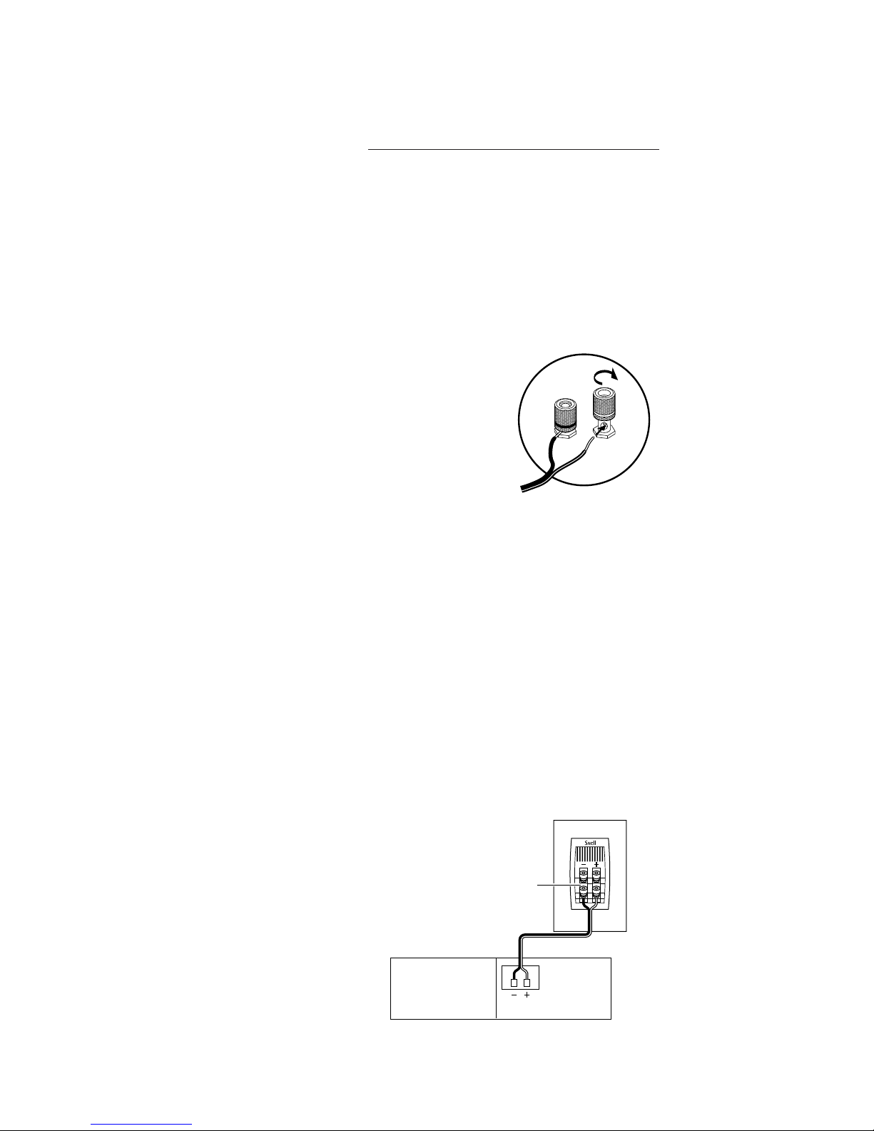
Connecting with Bare Wire
Insert bare wire into holes and tighten.
Connecting with Banana Plugs, Pins or
Spade Lugs
The binding posts accept standard banana plugs and
pins, and can accommodate 5/16" or larger spade lugs.
Warning! To prevent electrical shock, always switch off
the amplifier or receiver when making connections to
the speaker system.
Basic Connections
uKeep the speaker terminal jumper straps in place.
uWhen making connections, be sure to connect + to
+ (red) and – to – (black).
receiver or amplifier
XA60
speaker terminal
jumper straps

8
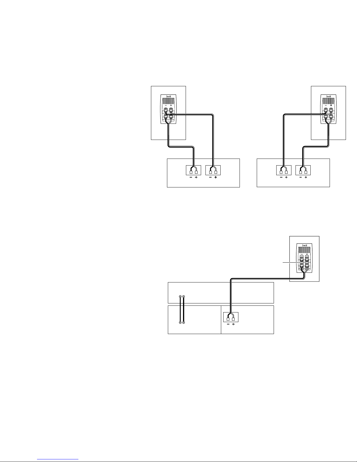
BI-WIRING AND BI-AMPING
XA60
amplifier or receiver
left speakerright speaker
low-frequency amplifier
high-frequency amplifier
Bi-Wiring
1. Use equal lengths of the appropriate wire when bi-
wiring each speaker. Consult your dealer for cable
options.
2. Unscrew both sets of terminals and remove the
jumper straps.
Bi-Amplifying
Using one amplifier for the bass and one
for the high end
1. Unscrew both sets of terminals and
remove the jumper straps.
2. Connect the cables from the bottom set
of terminals to the low frequency
amplifier driving the bass units.
3. Connect the cables from the top set of
terminals to the high frequency amplifier
driving the tweeters.
uDo not use an external crossover. It will
interfere with the phase and frequency
response.
9
Using one amplifier for each speaker
uMake sure that the amplifiers are identical.
1. Unscrew both sets of terminals and remove the
jumper straps.
2. Connect the cables from the bottom set of terminals
to the first amplifiers right channel.
3. Connect the cables from the top set of terminals to
the first amplifiers left channel.
4. Repeat steps 2 and 3 above for the second amplifier.
left speakerright speaker
right channel amplifier left channel amplifier
Using with a multichannel Surround Processor
1. Select the Large setting on your receiver or
processor for your main speakers. This routes all bass
information (typically below 100Hz) to your XA
Towers.
2. Match the sound levels of each speaker.
uYour home theater system most likely includes a
test signal that simplifies level matching. Refer to
the instructions provided with these electronics.
XA60
speaker terminal
jumper straps
amplifier or receiver
surround processor
out
in

10
OPTIMIZING THE SOUND
XA 60 Crossover Controls
Setting the Placement Switch
(Input Terminal Plate, far left switch)
Freestanding placement:
uSet the Bass Loading Switch to Normal.
Boundary placement:
uSet the Bass Loading Switch to Boundary.
Asymmetrical placement:
uBased on your room layout, you might find that one
speaker performs best in the Boundary setting, and
the other in the Normal setting. Use the following
information as guidelines. Don’t be afraid to make
final settings by ear to suit your taste.
Setting the Treble Level
(Middle Switch)
uThe Treble Level Control contours the brightness of
the XA Tower. Turn the Treble Control to “+” to
increase the high-frequency output in situations in
which the XA Tower sounds dull.
uTurn the Treble Control to “–” when the XA Tower is
overly bright, especially in highly reflective rooms.
uThe “+” position is closer to anechoically flat,
although the “–” position is preferable for many
recordings.
uThe ”–” position is similar to a processor “cinema re-
EQ” setting.
Setting the Rear-Firing Tweeter
(Input Terminal Plate, far right switch)
uThe rear-firing tweeter adds spaciousness and
ambiance to the soundstage, and is particularly
effective when the XA Tower is placed at least 12
inches (30cm) from a back wall.
Turn the Rear-Firing Tweeter OFF When:
uThe XA Tower is placed directly against a back wall.
uThe soundstage sounds too bright for your taste.
POWER-HANDLING
The power recommendation for the system assumes you
will operate the amplifier in a way that will not produce
distortion. All speakers can be damaged by a modest
amplifier if it is producing distortion. If you hear a gritty
noise or other signs of strain, immediately turn down
the volume. Prolonged or repeated operation of your
speakers with a distorted signal can cause damage that
is not covered by the warranty.
CARING FOR YOUR SPEAKERS
For Painted Finishes (Including baffles, backs,
bases, and metal grilles.)
uUse a soft terry cloth towel slightly dampened with
water, glass cleaner or a diluted mild detergent. The
towel should be just damp enough to wipe the
surface clean without leaving a trail of moisture. Be
very careful to not apply pressure to the fronts of
the drive units.
uDo not use abrasive cleaners or any cleaner
containing chemicals harsher than those found in
glass cleaner.
For Oiled Natural Wood Finishes
To remove dust and fingerprints, use the same technique
as above.
uIf your veneer begins to dry, apply a light coat of
rose or lemon wood oil. This should return the wood
to its original richness.
uDo not use spray waxes. These will create a buildup
and eventually cause the veneer to appear dull.
Note: Your veneers appearance and color will
naturally mature and perhaps darken over time.
uAvoid placing speakers in extreme conditions. If
direct sunlight is unavoidable, be sure that there is
nothing partially covering the veneer in order to
prevent “tan lines”.
uAvoid placing speakers where they could be subjected
to standing water. It will cause the wood to swell,
breaking apart glue joints and ruining the air seal.
Grilles
You can remove the grilles from the speaker system and
wipe them with a damp cloth to remove any dust.

11
LIMITED WARRANTY
For five years from the date of purchase, Snell Acoustics
will repair for the original owner any defect in materials
or workmanship that occurs in normal use of the
speaker system, without charge for parts and labor.
Your responsibilities are to use the product according to
the instructions supplied, to provide safe and secure
transportation to an authorized Snell Acoustics service
representative, and to present proof of purchase from an
authorized Snell dealer in the form of your sales slip
when requesting service.
Excluded from this warranty is damage that results from
abuse, misuse, accidents, shipping, repairs, or modifica-
tions by anyone other than an authorized Snell
Acoustics service representative. This warranty is void if
the serial number has been removed or defaced.
This warranty gives you specific legal rights, and you
may also have other rights that vary from state to state.
If Service Seems Necessary
Contact the dealer from whom you purchased the
speaker system. If that is not possible, call us at 978-
373-6114, or write to:
Snell Acoustics
143 Essex Street
Haverhill, MA 01832
We will promptly advise you of what action to take. If it
is necessary to return your speaker system to the
factory, please ship it prepaid in the original factory
packaging. Please note that Snell Acoustics will not be
held liable for shipping damage due to improper
packaging. After it has been repaired, we will return it
freight-prepaid in the U.S. or Canada.

143 Essex Street
Haverhill, MA 01832
phone: 978-373-6114
fax: 978-373-6172
email: info@snellacoustics.com
www.snellacoustics.com
©1999 Snell Acoustics.
All Rights Reserved.
Specifications are subject
to change without notice.
Covered by patents issued
and or pending.
Part #542-1010
Table of contents
Other Snell Speakers manuals

Snell
Snell AMC 6030 User manual

Snell
Snell OH-R7 User manual

Snell
Snell K7 User manual

Snell
Snell AMC 770 User manual

Snell
Snell Illusion A User manual

Snell
Snell QBx Surround User manual

Snell
Snell IC-K7 User manual

Snell
Snell AMC 2000 User manual

Snell
Snell 650r User manual

Snell
Snell AMC Sub 88 User manual

Snell
Snell SR7 Series 7 User manual

Snell
Snell IW-D7 User manual

Snell
Snell ICS570 User manual

Snell
Snell IW-T7 User manual

Snell
Snell AMC 730 User manual

Snell
Snell QBx 20 Monitor User manual

Snell
Snell XA Series User manual

Snell
Snell XA1900THX User manual

Snell
Snell XA 55cr User manual

Snell
Snell XA 1900THX User manual


