Snell OH-R7 User manual

Owner‘s Manual
OH
-
R7
In-Ceiling Loudspeaker

3
TABLE OF CONTENTS
Specifications 4
Introduction 5
About Installation 5
Placement 5
Music System Installation Locations 6
Home Theater Installation Locations 6
Installation Preparation 7
Required Clearance 7
Installation Site 7
Optional New Construction Brackets 7
Fire-Rated Boxes 7
Grille Removal 7
Bi-Wiring/Bi-Amplification 7
Installation 8
Redirecting the Midrange/Tweeter Baffle 9
Adjusting Bass Response 9
Boundary Compensation 9
Grille Installation 10
Painting 10
Painting the Speaker Frame 10
Painting the Speaker Grille 10
Listening Levels And Power Handling 11
Limited Warranty 11

4
SPECIFICATIONS
Frequency Response (±3dB)
Nominal Impedance
Recommended Amplifier Power
Sensitivity [1 watt (2.83v) at 1m]
Tweeter
Midrange
Woofer
Crossover Frequencies
External Dimension
Mounting Hole Opening
Mounting Depth
48–22,000Hz
4 ohms
10–200 watts
89dB
3/4-inch (19mm) soft dome
3” (75mm) soft dome
8” (200mm) copolymer cone
400 Hz / 2.5 kHz
127/16” (315mm) diameter
107/8” (276mm) diameter
6” (153mm)

5
INTRODUCTION
Snell Performance From an In-Ceiling Speaker
The Snell OH-R7 speaker provides the exceptional Snell sound from an in-ceiling speaker. In addition the OH-R7 incor-
porates an angled, rotatable midrange/tweeter baffle that enables it to deliver ideal imaging characteristics in virtually
any installation situation. This is particularly important in home theater installations. In these installations front
channel speaker need to project sound directly toward the listener, but surround speakers need to direct their sound
away from the listener to produce a diffuse sound. The woofer is positioned at an angle behind the midrange/tweeter,
delivering its sound through a crescent-shaped opening.
The OH-R7 features a boundary compensation switch that allows the sound of each speaker to be adjusted to produce
the best sound possible wherever it is installed.
Rugged paintable aluminum grilles and easy-to-use mounting hardware make the OH-R7 easy to integrate, visually
and mechanically into any installation.
ABOUT INSTALLATION
Warning – Always turn off the amplifier or receiver when connecting speakers or any other components to the system.
Note – Installation should only be performed by professional installers or those possessing skills in construction, expe-
rience with the proper use of hand and power tools, knowledge of local building and electrical codes, and familiarity
with the environment in which the OH-R7 will be installed. Install the speakers to meet all local building, energy, and
electrical codes.
PLACEMENT
Since the speaker installation is permanent and the furniture placement may not be, you should first determine the
best long-term location for the speakers — one that will accommodate relocation of the furniture in the room while
still providing well-balanced sound to the primary listening area.
The tweeter and midrange baffle of the speaker is angled to deliver accurate
on-axis response to the listening area. The baffle must be properly posi-
tioned to deliver the best sound. The illustration shows how the sound is
directed relative to the position of the midrange/tweeter baffle position.

6
Music System Installation Locations
For best results from a music system, place the speak-
ers on either side of the listening area and rotate the
baffle toward the listening area. Use multiple pairs for
optimum coverage in large rooms.
Note: The arrows and sound wave symbols ( )
indicate the direction of the speakers’ dispersion. Rotate
the baffle so that the arrow points toward the center of
the listening area.
Home Theater Installation Locations
LCR (Left/Center/Right)
When using the OH-R7 as a front left or right channel
speaker install them as close as possible to the front
wall. They should not be too much farther apart than
the width of the television screen. If more separation is
required you can compensate to some extent by angling
the midrange/tweeter baffle in toward the seating area.
When used as a center channel speaker the OH-R7
should be located on the same plane as the television.
Surround Speakers
When the OH-R7 is used as a surround speaker, it can be
used as configured as either a direct or diffuse surround
speaker. For direct operation, orient the speaker baffle
toward the seating area. For diffuse operation, turn the
speaker baffle toward a back wall or corner.
Note: See the Boundary Compensation switch section
if the speakers are mounted closer than 18-inches to an
adjacent wall or 24-inches from a corner.
direct sound
diffuse sound

7
INSTALLATION PREPARATION
Required Clearance
A mounting hole template is included with the OH-R7. An additional 1” of clearance is
required around the mounting hole cut. This allows room for the grille flange and for the
mounting clamps. There must be at least 6” of depth, measured from the front of the
mounting surface.
Installation Site
Performance of the OH-R7 will be enhanced if the cavity behind the installation location is
filled with standard fiberglass insulation. If there is already insulation in the ceiling that has
a paper backing facing the speaker, remove the backing in the area behind the installation
location. (Consult local building codes for compliance.)
Taking steps to increase the rigidity of the
mounting surface by using additional dry-
wall screws, and/or construction adhesive
between the drywall and joists adjacent to
the speaker location, will further enhance
performance.
Optional New Construction
Brackets
For new construction installations, we offer
new construction brackets. The NCB brack-
ets act as a perfect guide when cutting the
wallboard.
Fire-Rated Boxes
For new construction installations we of-
fer a fire-rated back box (FRB) solution to
satisfy local fire codes.
Grille Removal
If you need to remove the grille, gently lift it out at the edges. Use a sharp pointed instrument such as an awl or a
heavy paper clip bent to serve as a tool.
Bi-Wiring/Bi-Amplification
If you are bi-wiring or bi-amplifying your OH-R7 loudspeakers, you must move the jumper from the “NORMAL” termi-
nal to the “BIAMP” terminal or you risk damaging your speakers and your amplifier.
107/8"
276mm
127/8"
326mm
Joist
Ceiling
Material
Fiberglass lining
Additional drywall screws
Adhesive between studs
and drywall

8
INSTALLATION
Mark the outline of the installation hole using the supplied template. Make a small hole at the center of the speaker
location. Insert a long, bent piece of wire and rotate it to confirm that there are no obstructions behind the location.
Warning: Do not overtighten the screws.
Cut the installation hole. Run the wire from the amplifier location to the cutout. Allow for an extra foot of wire at the
cutout.
Strip 1/2-inch (13mm) of insulation from the wire, and twist the wire strands together. The speaker jack will accept
either bare wire up to 12-gauge or single banana plugs. Connect the wire to the speaker.
Slide the speaker into the cutout. Tighten the four Phillips mounting screws. The mounting arms will pivot into posi-
tion and clamp the speaker to the mounting surface.
9
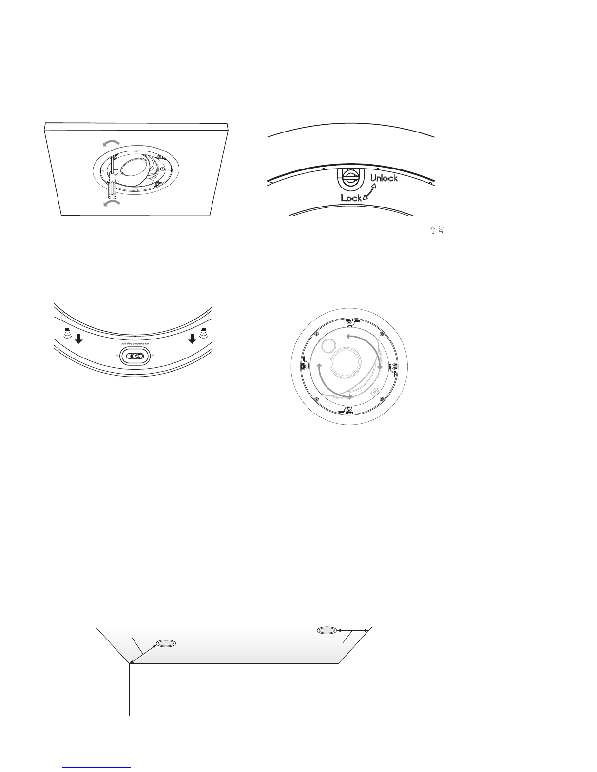
REDIRECTING THE MIDRANGE/TWEETER BAFFLE
To rotate the speaker baffle, first turn the four flat head screws 90º counterclockwise into the “Unlock” position.
Rotate the baffle so that the midrange/tweeter array points in the desired direction. The arrows and sound waves “ ”
indicate the direction of the speakers’ dispersion. Rotate the baffle so that the arrows point toward the center of the
listening area for direct operation and toward a corner for diffuse operation. Refer to the “Placement” section for
more information.
Warning: Do not press on the tweeter or midrange domes. Rotate with the outside edge of the baffle.
Less than 24"/61cm – Boundary Compensation ON
More than 24"/61cm – Boundary Compensation OFF
Less than 18"/46cm – Boundary Compensation ON
More than 18"/46cm – Boundary Compensation OFF
ADJUSTING BASS RESPONSE
If you are using your loudspeakers with a surround sound processor and subwoofer, set the bass management control
of the electronics to “small.” Consult your surround receiver’s or processor’s manual for instruction on the changing
bass management settings.
Boundary Compensation
The response of a speaker changes when it is mounted close to the boundary junctions of a room (near an adjacent
wall or close to the corners of the room). The OH-R7 has been carefully voiced to compensate for these boundary ef-
fects.
Set the Boundary Compensation Switch to “ON” if:
The speaker is mounted less than 18-inches (46cm) from the junction of two surfaces (wall/ceiling).
The speaker is mounted less than 24-inches (61cm) from the junction of three surfaces (a room corner).

10
GRILLE INSTALLATION
If you wish to paint the frames or grilles of your speakers it should be done prior to installation of the grille. Refer to
the painting instructions that follow. If you will not be painting the speakers speaker you can install the grille now. A
decorative scrim is attached to the grille of the speakers. A wax paper sheet is used to protect the scrim during ship-
ment. Remove the wax paper sheet before installing the grille.
To install the grille simply press it into the speaker frame.
Warning: If you are planning to install the tie-tack logo on the grille, do not install the logo directly over the tweeter.
It is possible for the pin to make contact with and possibly damage the dome of the tweeter
PAINTING
Painting the Speaker Frame
The speakers may be painted before or after they are installed. They are already primed.
Insert the supplied paint shield before you paint the frame. If you are using spray paint, apply two light coats. If you
are applying paint with a brush or roller, thin the paint and apply two very light coats. This helps prevent excessive
paint buildup and “runs” on the frame.
After the paint has dried, use the finger pulls to remove the paint shield.
Painting the Speaker Grille
Remove the protective wax paper from the scrim then carefully remove the scrim. Place the scrim on the wax paper to
keep the adhesive clean while painting the grille.
If you are using spray paint, apply two light coats. If you are applying paint with a brush or roller, thin the paint and
apply two very light coats. This helps prevent paint from filling the holes in the grille.
After the paint is dry, reinstall the cloth and grille logo. Note the warning in the precious section regarding the posi-
tion of the logo to avoid damage to the tweeter dome.

11
LISTENING LEVELS AND POWER HANDLING
The power recommendation for the system assumes you will operate the amplifier in a way that will not produce dis-
tortion. All speakers can be damaged by even a modest amplifier if it is producing distortion. If you hear a gritty noise
or other signs of strain, turn down the volume. Prolonged or repeated operation of your speakers with a distorted
signal can cause damage that is not covered by the warranty. It is especially important that you do not overdrive the
bass capability of smaller speakers. Watch for noises, such as pops, caused by the music’s bass line. Use of the loudness
control and/or full bass boost at louder volumes is likely to overdrive the woofer. Use such controls sparingly.
LIMITED WARRANTY
For five years from the date of purchase, Snell Acoustics will repair for the original owner any defect in materials or
workmanship that occurs in normal use of the speaker system, without charge for parts and labor.
Your responsibilities are to use the product according to the instructions supplied, to provide safe and secure trans-
portation to an authorized Snell Acoustics service representative, and to present proof of purchase from an authorized
Snell dealer in the form of your sales slip when requesting service.
Excluded from this warranty is damage that results from abuse, misuse, accidents, shipping, repairs, or modifications
by anyone other than an authorized Snell Acoustics service representative. This warranty is void if the serial number
has been removed or defaced.
This warranty gives you specific legal rights, and you may also have other rights that vary from state to state.
If Service Seems Necessary
Contact the dealer from whom you purchased the speaker system. If that is not possible, call us at 978-538-6262, or
write to:
Snell Acoustics
300 Jubilee Drive, P.O. Box 3717
Peabody, MA 01961-3717
We will promptly advise you of what action to take. If it is necessary to return your speaker system to the factory,
please ship it prepaid in the original factory packaging. Please note that Snell Acoustics will not be held liable for
shipping damage due to improper packaging. After it has been repaired, we will return it freight prepaid in the U.S. or
Canada.
For EU Customers Only
This symbol found on the product indicates that the product must not be disposed of with household waste. Instead,
it may be placed in a separate collection facility for electronic waste or returned to a retailer when purchasing similar
product. The producer paid to recycle this product. Doing this contributes to reuse and recycling, minimizes adverse
effects on the environment and human health and avoids any fines for incorrect disposal.

300 Jubilee Drive, P.O. Box 3717
Peabody, MA 01961-3717
phone: 978-538-6262
fax: 978-538-6266
email: info@snellacoustics.com
web: www.snellacoustics.com
©2007 Snell Acoustics.
All Rights Reserved.
Specifications are subject
to change without notice.
Covered by patents issued
and or pending.
Part #542-1045
Table of contents
Other Snell Speakers manuals

Snell
Snell AMC 460 User manual

Snell
Snell AMC 360 User manual

Snell
Snell QB 25 Series User manual

Snell
Snell AMC 770 User manual

Snell
Snell AMC Sub 88 User manual

Snell
Snell AMC550mp User manual

Snell
Snell J7 User manual

Snell
Snell AMC 6030 User manual

Snell
Snell Type C User manual

Snell
Snell IC-B7S User manual

Snell
Snell ICS 570 User manual

Snell
Snell IW-T7 User manual

Snell
Snell 730 770 830 870 User manual

Snell
Snell CLS.5 User manual

Snell
Snell AMC 680 User manual

Snell
Snell AMC 650R User manual

Snell
Snell IW-K7 User manual

Snell
Snell QBx 20 Monitor User manual

Snell
Snell AMC 360 User manual

Snell
Snell XA Series User manual


