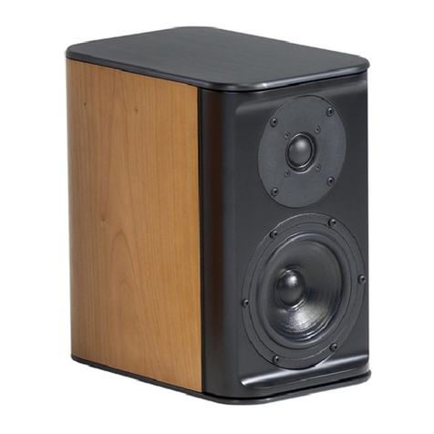
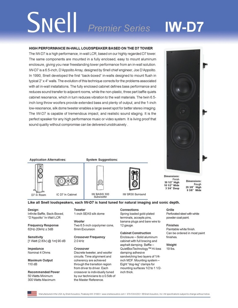
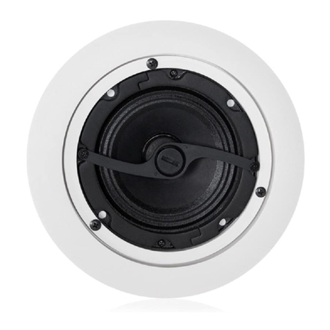
Snell IC-K7 User manual

IC-K7
IC-CR7
IC-LCR7
IC-D7
Owner’s Manual
IC-K7-CR7-LCR7-D7 - Final.indd 1IC-K7-CR7-LCR7-D7 - Final.indd 1 11/3/08 5:51:03 PM11/3/08 5:51:03 PM

2
SPECIFICATIONS
Frequency Response (±3dB)
Recommended Amplifier
Nominal Impedance
Sensitivity (2.83v at 1m)
Tweeter
Bass Driver
Crossover Point
Boundary Compensation
Grille
Dimensions
(HxWxD)
Finish*
Weight
* Custom paint and grilles are available for an extra charge
IC-CR7
80 Hz–20 kHz
50–150W
4 ohms
88dB SPL
1” Vifa silk dome, ferrofluid
cooling
Dual 4-inch (102mm) poly
cone, 4.5mm excursion
2.5 khz
No
Black cloth over MDF frame
19 x 6 x 9 inches
(483 x 152 x 229mm)
depth includes 7/16” (12mm) grille
Textured black paint
18 lbs (8.16kg) / each
IC-K7
56 Hz–20 kHz (bass reflex)
77 Hz–20kHz (with port plug)
100–300W
8 ohms
87dB SPL
1” SEAS silk dome, ferrofluid
cooling
51/4-inch (132mm) SEAS treated
paper cone, 5mm excursion
2.5 khz
Yes
Black cloth over MDF frame
117/8x 7 x 107/16 inches
(302 x 178 x 265mm)
depth includes 7/16” (12mm) grille
Textured black paint
15 lbs (6.8kg) / each
IC-K7 IC-CR7
IC-K7-CR7-LCR7-D7 - Final.indd 2IC-K7-CR7-LCR7-D7 - Final.indd 2 11/3/08 5:51:03 PM11/3/08 5:51:03 PM

3
IC-LCR7
75 Hz-20 kHz
50–300W
4 ohms
90dB SPL
1” SEAS silk dome, ferrofluid
cooling
Dual 51/4-inch (132mm) treated
paper cone, 5mm excursion
2kHz
Yes
Black cloth over MDF frame
19 x 7 x 83/4inches
(483 x 178 x 223mm)
depth includes 7/16” (12mm) grille
Textured black paint
20 lbs (9.07kg) / each
IC-D7
62 Hz-20 kHz
50–300W
4 ohms
90dB SPL
1” SEAS silk dome, ferrofluid
cooling
Dual 61/2-inch (165mm) copolymer with butyl
rubber surround, 5mm excursion
2kHz
Yes
Black cloth over MDF frame
191/2x 73/4x 11 inches
(496 x 197 x 280mm)
depth includes 7/16” (12mm) grille
Textured black paint
30 lbs (13.6kg) / each
IC-LCR7 IC-D7
IC-K7-CR7-LCR7-D7 - Final.indd 3IC-K7-CR7-LCR7-D7 - Final.indd 3 11/3/08 5:51:04 PM11/3/08 5:51:04 PM

4
INTRODUCTION: HIGH END PERFORMANCE IN A PLAIN WRAPPER
The Snell IC (In-Cabinet) series units bring the acclaimed performance of the elegant Series 7
loudspeakers to the integrated applications in custom cabinetry. These In-Cabinet loudspeakers
deliver performance that is as close as possible to our highly-regarded, free-standing models,
such as the K7 and LCR7. To do so several issues were addressed.
All four of these designs feature the same high-quality, rugged construction of our furniture-
grade veneer cabinets. To be deployed in “built-in” applications, the sonic performance
compensated for the typical cabinet boundaries encountered. Conventional bookshelf speakers
sound “chesty” and image poorly when use for in-cabinet applications. These unique designs
solve these problems and provide the discerning listener with the same engaging experience in
a “hide-away” package as the more traditional loudspeaker box.
These in-cabinet designs use the same high-quality parts as their in-room counterparts — High
excursion woofers, wide dispersion tweeters, low resonance cabinets and audiophile grade
crossovers components all ensure that the experience is clean, impactful and effortless, just like
the in-room speakers from which they are derived.
PLACEMENT OF THE FRONT CHANNEL SPEAKERS
A home theatre system includes three loudspeakers placed across the front of the listening
room. The distance between the left and right speakers determines the width of the stereo
image. If the speakers are placed too close together, the image will be too narrow; too far apart
and the blend will suffer, creating a hole in the middle. When properly placed, your speakers
will create a continuous “virtual image” from left to right, with an illusion of sound outside, in
front of, and behind the speaker systems.
We recommend an angular separation between 45 degrees and 60 degrees (when viewed from
above). This is equivalent to a separation between the speaker systems that is about 85% of the
distance to either of the speakers.
Creation of sounds between the speakers requires
some precise placement. The distance from the
left speaker, right speaker, and center channel
to the listener location should all be as equal
as possible. We advise using a tape measure to
equalize these two distances to the primary
listening location.
Ideally the front channel speakers should be in-
stalled at the same height as the ears of a seated
listener. Try to keep the front channel tweeters
within two vertical feet of that height.
LISTENING
AREA
45° - 60°
IC-K7-CR7-LCR7-D7 - Final.indd 4IC-K7-CR7-LCR7-D7 - Final.indd 4 11/3/08 5:51:04 PM11/3/08 5:51:04 PM

5
PLACEMENT OF THE SURROUND SPEAKERS
There are many opinions about where surround or “rear” speakers should be mounted. The
following is based on the findings of the best academics, and on our experience with many in-
stallations. These placement recommendations apply to all the IC models. The illustration below
shows the speakers custom-installed in recesses in the wall. Alternatively the equivalent in-wall
models could be used.
If two surrounds are used in a standard 5.1 configuration (not 7.1 or EX), they are best mounted
to the sides of the listening area. This means straight to the sides of the listener or in line with
the primary row of seating, plus or minus 15 degrees. This is preferred over back wall mounting
for several reasons: It places the surrounds at locations where the difference between left ear
and right ear discrimination is at a maximum. This gives the maximum sense of “envelopment”
or being surrounded by sound. Rear mounted speakers force a huge angular gulf between the
front primary speakers and the rear speakers. The sound image is inherently discontinuous. Also,
front to rear aural discrimination is not very strong. Differentiation between front and rear
speakers will not be as strong as the effect of adding speakers to the side. 7.1 or EX systems
that use side and rear speakers together overcome all of these obstacles and give both maxi-
mum envelopment and a more continuous surround effect.
A second factor to consider is the evenness of sound coverage over the seating area. Most
surround processors have features for setting the balance of all channels. A circulating noise
signal is adjusted in each channel until the apparent or measured sound level is even. Of course,
moving to another seat will shift this balance somewhat. Well-placed surround speakers will
minimize the level variation from seat to seat. The best way to achieve evenness is to increase
the distance of the surround speakers from the listening area. Mount them high on the side
walls or even on the ceiling. As a good rule of thumb, surrounds should be on the side walls at
least one foot above the height of a standing listener. If the speakers are ceiling-mounted, they
should be close to the side walls, well away from an overhead position.
If a large theater room with three or more rows of seats is planned, then more than one pair of
surround speakers should be used to give more even coverage and a more diffuse sound field.
We recommend that a pair of surrounds be used for every other seating row (the first, the third,
the fifth, etc.). This follows standard cinema practice.
/PTIONAL$IRECT2ADIATION
3URROUND3PEAKER,OCATIONS
IC-K7-CR7-LCR7-D7 - Final.indd 5IC-K7-CR7-LCR7-D7 - Final.indd 5 11/3/08 5:51:04 PM11/3/08 5:51:04 PM

6
Use equal lengths of the appropriate wire
to bi-wiring the speakers. Consult your
dealer for cable options. Connect the
wires between the amplifier and speakers
as illustrated.
CONNECTING THE SPEAKERS
Map out the wiring paths from the speakers to the amplifier. We recommend 16-gauge wire for
runs up to 25 feet, and 14-gauge wire for longer runs. Be sure the speaker wire does not rest or
rub against any sharp or pointed objects. Allow an extra foot of wire at the speaker location to
make it easier to connect the speaker before setting it in position .
For normal, single wire connection, unscrew (turn counter-clock-
wise) one set of the terminal knobs. Strip about 1/2” (12mm) of
the insulation from the two wire conductors and twist the wire
strands into a tight bundle. Insert the wire into the hole in the
terminal shaft and turn the terminal knob clockwise to clamp
the wire in place. Be sure there are no loose strands of wire that
could touch the other terminal.
Be sure the positive and negative speaker terminals of the am-
plifier are connected to the corresponding + (red) and – (black)
terminals of the speakers. All wire is marked in some way to
make it easy to trace the connections. The two conductors will
be color coded, or there will be a stripe or ridge on the insula-
tion, to identify them.
The terminals also accept wires with pin lugs or spade lugs at-
tached. Dual banana plugs can also be plugged into the back of
the terminals.
When connecting more than two speakers per amplifier channel, you should use series/parallel
wiring. In all cases, make certain that the total impedance does not fall below the amplifier’s
rating. If you are not sure, contact your Snell Acoustics dealer.
BI-WIRING
High performance audio systems can benefit from bi-wiring the speakers.
This involves connecting two sets of wires between the amplifier and the
speakers. If you are bi-wiring your speakers removed the terminal straps
by loosing the terminal knobs and sliding the straps to the side.
amplifier
IC-K7-CR7-LCR7-D7 - Final.indd 6IC-K7-CR7-LCR7-D7 - Final.indd 6 11/3/08 5:51:04 PM11/3/08 5:51:04 PM

7
LISTENING LEVELS AND POWER HANDLING
The power recommendation for the system assumes you will operate the amplifier in a way
that will not produce distortion. All speakers can be damaged by even a modest amplifier if it is
producing distortion. If you hear a gritty noise or other signs of strain, turn down the volume.
Prolonged or repeated operation of your speakers with a distorted signal can cause damage
that is not covered by the warranty. It is especially important that you do not overdrive the
bass capability of smaller speakers. Watch for noises, such as pops, caused by the music’s bass
line. Use of the loudness control and/or full bass boost at louder volumes is likely to overdrive
the woofer. Use such controls sparingly.
HOW TO CARE FOR YOUR SPEAKERS
/Use a soft terry cloth towel slightly dampened with water, glass cleaner, or a diluted mild
detergent. The towel should be just damp enough to wipe the surface clean without leaving
a trail of moisture.
/Do not use abrasive cleaners or any cleaner containing chemicals harsher than those found
in glass cleaner.
LIMITED WARRANTY
For five years from the date of purchase, Snell Acoustics will repair for the original owner any
defect in materials or workmanship that occurs in normal use of the speaker system, without
charge for parts and labor.
Your responsibilities are to use the product according to the instructions supplied, to provide
safe and secure transportation to an authorized Snell Acoustics service representative, and to
present proof of purchase from an authorized Snell dealer in the form of your sales slip when
requesting service.
Excluded from this warranty is damage that results from abuse, misuse, accidents, shipping,
repairs, or modifications by anyone other than an authorized Snell Acoustics service representa-
tive. This warranty is void if the serial number has been removed or defaced.
This warranty gives you specific legal rights, and you may also have other rights that vary from
state to state.
If Service Seems Necessary
Contact the dealer from whom you purchased the speaker system. If that is not possible, call us
at 607-352-2488, or write to: Snell Acoustics
2 Chambers Street
Binghamton, NY 13903
We will promptly advise you of what action to take. If it is necessary to return your speaker
system to the factory, please ship it prepaid in the original factory packaging. Please note that
Snell Acoustics will not be held liable for shipping damage due to improper packaging. After it
has been repaired, we will return it freight prepaid in the U.S. or Canada.
For EU Customers Only
This symbol found on the product indicates that the product must not be disposed
of with household waste. Instead, it may be placed in a separate collection facility
for electronic waste or returned to a retailer when purchasing similar product. The
producer paid to recycle this product. Doing this contributes to reuse and recycling,
minimizes adverse effects on the environment and human health and avoids any
fines for incorrect disposal.
IC-K7-CR7-LCR7-D7 - Final.indd 7IC-K7-CR7-LCR7-D7 - Final.indd 7 11/3/08 5:51:05 PM11/3/08 5:51:05 PM

2 Chambers Street
Binghamton, NY 13903-2699
phone: 607-352-2488
fax: 607-352-2498
email: [email protected]
www.snellacoustics.com
©2009Snell Acoustics. All Rights Reserved.
Specifications are subject to change without notice.
Covered by patents issued and/or pending.
Part #542-1060
IC-K7-CR7-LCR7-D7 - Final.indd 8IC-K7-CR7-LCR7-D7 - Final.indd 8 11/3/08 5:51:05 PM11/3/08 5:51:05 PM
This manual suits for next models
3
Table of contents
Other Snell Speakers manuals
Snell
Snell IC-B7S User manual

Snell
Snell SR.5 Surround User manual

Snell
Snell Type C User manual
Snell
Snell QB 25 Series User manual
Snell
Snell AMC 730 User manual
Snell
Snell AMC 770 User manual
Snell
Snell 650r User manual
Snell
Snell AMC 460 User manual

Snell
Snell Illusion A User manual

Snell
Snell A-III User manual
Snell
Snell AMC 360 User manual
Snell
Snell AMC 360 User manual

Snell
Snell AMC 680 User manual
Snell
Snell AMC 6030 User manual
Snell
Snell IC-LCR7 User manual
Snell
Snell AMC 560 User manual

Snell
Snell AMC 800 User manual
Snell
Snell XA 1900THX User manual
Snell
Snell 730 770 830 870 User manual

Snell
Snell QBx Surround User manual
