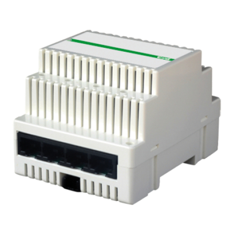
snode SN0001A User manual

User Guide
Model No. : SN0001A
ersion 1.0

SN0001A
User Guide
REVISION HISTORY
1.0 20 Dec-2022 Release SN0001A Mahendra Sondagar
Version Date Note Approver
www.snode.io
@2022 DOTCOM iot LLP. All Rights Reserved.
2

SN0001A
User Guide
TABLE OF CONTENT
3
.snode.io
@2022 DOTCOM iot LLP. All Rights Reserved.
1 About this Guide ........................................................................................................................................................... 4
2 Introduction ..................................................................................................................................................................... 4
3 Connecting the Hard are ..................................................................................................................................... 9
2.1 Product Overvie ............................................................................................................................................. 4
2.2 Specification ........................................................................................................................................................ 5
3.1 S-node Modular Gate ay Configuration.........................................................................................
(i) Gate ay Motherboard.................................................................................................................. 11
(ii) Gate ay RF Frontend....................................................................................................................
3.1.1 Connect to the Net ork................................................................................................................... 11
3.2 S-node Configuration................................................................................................................................... 1
3.2.1. Po er up the S-node....................................................................................................................... 1
3.2.2 Choose The Installation Surface.............................................................................................. 1
3.2.3 Install the S-node............................................................................................................................... 1
3.2.4 Configure the S-node..................................................................................................................... 22
FCC Compliance Statement (USA)......................................................................................................................... 24

SN0001A
User Guide
1 ABOUT THIS GUIDE
4
This manual describes how o configure he S-node and S-node Modular Ga eway. I
con ains specifica ions and se up informa ion for S-node and S-node modular
ga eways. Follow his manual exac ly for a comple e se up.
2 INTRODUCTION
2.1 Product Overview (S-Node)
S-node is a iny, ruly plug-and-play sensor node designed o enable predic ive
main enance a a finger ip.
S-node is able o measure 3D vibra ion, accos ic emissions, gas emissions, RPM and IR
hermal.
S-node send da a o he S-node modular ga eway by using RF 2.4 GHz and Ga eway
send ha da a o he S-node cloud using MQTT pro ocol.
A Highly scalable hardware archi ec ure allows for plugging he sensors on a node as
per he indus rial requiremen . La er on, machine learning algori hms will process da a
o es ima e machine down ime and genera e real- ime no ifica ions in he even of any
unexpec ed si ua ions, which will appear on he dashboard of he S-node.
FRONT
7 cm
6 cm
TOP
6 cm
4.5 mm
BOTTOM
6 cm
Micro US
Type-B
www.snode.io
+91
8591900
34
6
@2
0
22 D
O
T
CO
M io LLP. All Righ s Reserved.

SN0001A
User Guide
5
Parameters Specification
SoC/ CU 32-bit ARM® CortexTM -M4 CPU, 64 MHz,
Connectivity Stack OpenThread
Dimensions length 7cm, Diameter 6cm
Sensor Type MEMS based sensors
Weight 250 Gram
aterial Type Polycarbonate, Aluminum Base
ounting Type Neodymium Magnet
User Interface Web Application and Mobile Application
Certifications FCC, CE, IP67, UL95VO
Operating %(RH)
8
0
%
Storage Temperature
<
8
5
°
C
(18
5
°
F
)
w
ithout battery
Shock Resistance 2 meter
f
all,
1
6 g continuous
v
ibration
1.
5 dBi MA
X
GainIntegrate
d
A
ntenna
Po
w
er Source
Li-Po Battery
:
500mAh
/
3
.
7V,Charging Time i
2hours
w
ith 20
%
e
ff
ciency loss
USB Supply
:
5V
/1
A
System Supply Voltage 2
.
5V
On
b
oar
d
Storag
Capacity External FLASH-NOR Memory IC 32Mb
(
4M x
8
SPI -
Q
uad I
/
O 33MHz
8
-WSON
(
6x5
)
E
nterprise
-
gra
d
Security Mbed TLS
(
AES-EBC, EC
J
-PA
K
E, and SHA256
)
Operating Temperatur
Range -40
°
C to
8
5
°
C
B
attery
L
ife 2 to 3
Y
ears
(
Varies as per the application
and re
q
uirements
)
2.2 Specification
www.
snode
.
io
in
f
o
@
snode
.
io
+
9
1
8
59
1
900346
@
2022 DOTCOM iot LLP
.
All Rights Reser
v
ed
.

SN0001A
User Guide
6
3 Connecting The Hardware
3.1 S-node Modular Gateway Confi uration
S-node modular gateway is plug and play device. S-node modular gateway collects
information from s-node and transmit the data to the cloud. S-node modular gateway
is combination of two devices
Gateway Motherboar
Gateway RF Frontend
A.
B.
A. Gateway Motherboard
The Gateway motherboard has dual Gigabit Ethernet connectors and dual USB 3.0
ports, which makes it suitable for soft router applications that require less hardware. It
have 4 GB RAM and 32 GB eMMC storage allow for quick boot-up times and a
seamless overall experience.
The S-node Modular gateway includes a range of I/O peripherals such as MIPI CSI,
MIPI DSI, micro-HDMI to connect displays/cameras, a standard 9-pin USB 3.0 header
for additional USB expansion, and an FPC connector all packaged in a compact form
factor.
It has a PC/ABS case with an Aluminum alloy on top, which has a large sink to cool
down at extreme loads. This enclosure provides better protection and is ideal for
industrial applications. The case has long rubber feet for better stability when placed
on a flat surface and mounted in two different methods. One is to use the keyhole slot
wall mount and hang it on the wall in two different orientations or use the three
mounting holes and mount it onto a DIN rail.
www.snode.io
@2022 DOTCOM iot
LL
P. All Rights Reserved.

SN0001A
User Guide
7
FRONT VIEW B CK VIEW
SIDE VIEW
12
3
5
4
1. USB 3.
2. Ethernet Por
3. USB Type-C Port
4. Micro-SD card slo
5. Micro HDMI
www.snode.io
info@snode.io +91 8591900346
@2022 DOTCOM iot LLP. All Rights Reserved.

SN0001A
User Guide
8
Wall Mount
orizontal
Vertical
DIN Rail
www.snode.io
info@snode.io +91 8591900346
@2022 DOTCOM iot LLP. All Rights Reserved.

SN0001A
User Guide
9
Specification
Specification Details
Networ ing Dual Gigabit Ethernet Connectors
Processor Broadcom BCM2711 quad-core Cortex-A72 (ARM v8) 64-
bit SoC @ 1.5GHz
Operating temperature 0˚C to 80˚C
Dimensions (LxH) 101mm x 73mm
Compliance FCC , CE, EU DoC, UK DoC, RoHS
4GB LPDDR4
Memory
Storage 32GB eMMC
Connectivity
PCIe Gen 2 x1 interface
28 GPIO signals
SD card interface for SD card or external eMMC
Onboard Gigabit Ethernet PHY supporting IEEE1588
1
×
USB 2.0 interface
2.4GHz and 5.0GHz IEEE 802.11b
/
g
/
n
/
ac
W
i-Fi, Bluetooth 5.0,
BLE
w
ith onboard and external antenna options
Ports USB , Ethernet , Micro HDMI, Micro-SD card
www
.snode.io
info@snode.io
+9
1 85
9
1
9
00346
@2022 DO
T
COM iot LLP. All Rights Reserved.

SN0001A
User Guide
10
B. Gateway RF Frontend
Gateway RF frontend is one type of USB antenna which is convert data into RF. Also
Gateway RF Frontend is f lly scalable and moveable device.
There are some basic feat res of gateway RF frontend :
For installation, yo need to connect both devices first.
To connect both device follow the steps :
1.
2.
Set p the Gateway motherboard at appropriate place
Pl g in Gateway RF Frontend into Gateway motherboard (Pl g in into USB 3.0 port).
Specification Details
Operating Freq ency Range 2405 MHz to 2480 MHz
Antenna Model PCB antenna
Antenna Gain 1.5 db
Antenna Type B
Matching Network Pi-network
www.snode.io
info@snode.io +91 8591900346
@2022
D
OTCOM iot
LL
P. All Rights Reserved.

SN0001A
User Guide
11
3.1.1 Connect to the Network
To use the S-node Modular Gatewa , ou must power up the S-node modular gatewa
and connect it to the network.
To connect S-node Modular Gatewa to the Wi-Fi network, follow the step
which are below :
1. Initiall , the S-node Modular Gatewa is booted in hotspot mode, having "Borde
Router-AP" as the access point name.
Figure 1.1 Scan Wi-Fi network.
www.snode.io
info@snode.io +91 8591900346
@2022 DOTCOM iot LLP. All Rights Reserved.

SN0001A
User Guide
12
2. Using a mobile/laptop, connect t e Wi-Fi network to "BorderRouter-AP" wit t
password "12345678".
Figure 2.1 Connect wit Wi-Fi.
Figure 2.2 Enter your password.
www.snode.io
info@snode.io +91 8591900346
@2022 DOTCOM iot LLP. All Rig ts Reserved.

SN0001A
User Guide
13
4. Open the "10.4 .0.1:8080" address using any web browser, and open the S-Nod
Wi-Fi manager.
Figure 4.1 Opened S-Node Wi-Fi Manager.
3. Now, you can see that your S-node Modular Gateway is connected to the network.
Figure 3.1 Connected to Border_RouterAP.
www.snode.io
info@snode.io +91 8591900346
@ 0 DOTCOM iot LLP. All Rights Reserved.

SN0001A
User Guide
14
5. In the S-Node Wi-Fi manager, connect the gate ay to a kno n Wi-Fi net ork b
entering the Wi-Fi SSID and pass ord in the dynamic configuration tab.
6. Once, Gate ay motherboard is connected to net ork, the Wi-Fi disables th
hotspot mode.
7. (https://snode.io/) No , visit to the S-node login panel and enter the ID/Pass or
for login.
Figure 7.1 Login Panel
Figure 5.1 Enter SSID & Pass- ord.
.snode.io
info@snode.io +91 8591900346
@2022 DOTCOM iot LLP. All Rights Reserved.

SN0001A
User Guide
15
Figure 8. Gateway is online.
t
www.snode.io
info@snode.io +91 8591900346
@ 0 DOTCOM iot LLP. All Rights Reserved.
Figure 8.1 Gateway is offline.
8. Now, click on the configuration and check the status of the gateway. It will b
changed from offline to online.

SN0001A
User Guide
16
t
3 2 S-Node Configuration
Overview :
There is no particular skill or person required to install the S-node. Anyone can easily
install it with the help of the user guide
Power up the S-node
Choose The Installation Surface
Install the S-node
Configure the S-node.
3.2.1.
3.2.2.
3.2.3.
3.2.4.
3.2.1. Power up the S-Node.
First of all, remove the transparent cover from the S-node. Then, pull down the
switch present on the left side of the S-node.
A
Gateway
R
2.4 GHz MQTT
S-Node Dashboard
Pull Dow
Switch
1.
Blink LED2.
www.snode.io
info@snode.io +91 8591900346
@2022 DOTCOM iot LLP. All Rights Reserved.

SN0001A
User Guide
17
Initially, the bl e LED will begin blinking at a rate of 50
milliseconds, indicating S-node a to-commissionin
process is nderway.
B.
Once the node is commissioned s ccessf lly to th
network, the bl e led will stay on.
C.
Lastly, cover p the sensor node sing transparent
layer which is exactly looks like pict re.
D.
In the S-node ser dashboard, the config red device stat s will be pdated from
Offline to Online state.
E.
Fig re : E.1 S-Node is Online.
Note :
Description of LED Indicator
Bl e LED is off, it showa that S-node is not connected to the network or S-node is in sleep mode.
Bl e LED Flashes, it means S-node is connecting to the network.
Bl e LED is stable, it shows that S-node is connected to the network.
www.snode.io
info@snode.io +91 8591900346
@2022 DOTCOM iot LLP. All Rights Reserved.

SN0001A
User Guide
18
Figure: .2 S-node is offline.
Likewise, commission all the S-nodes.
3.2.2. Choose The Installation Surface.
Before installation, find the right surface of the element or machine, where you can
easily sense the data to predict the machine’s health.
A.
Note: Please wear protective gloves, masks, and glasses before installation of the S-node.
Not here
www.snode.io
info@snode.io +91 8591900346
@2022 DOTCOM iot LLP. All Rights Reserved.

SN0001A
User Guide
19
3.2.3. Installation of The S-node.
Mount the S-node directly because the S-node has a magnet at the bottom.A.
To clean the surface, use soap-water and microfiber.B.
www.snode.io
info@snode.io +91 8591900346
@2022 DOTCOM iot LLP. All Rights Reserved.

SN0001A
User Guide
20
Now, Roll the epoxy and apply on the bottom of S-node.D.
If surface is not able to stick with magnet than use Epoxy for installation.B.
Mix the epoxy as per the guidelines. (Take epoxy and begin mixing it until it
becomes soft. Check that it is not too hard or crumbly.)
C.
www.snode.io
info@snode.io +91 8591900346
@2022 DOTCOM iot LLP. All Rights Reserved.
Popular Gateway manuals by other brands
SSS Siedle
SSS Siedle Smart Gateway Professional Commissioning instructions
RTA
RTA 460BMSA-NNA4 Product user guide

D-Link
D-Link DVG-5004S user manual

SMC Networks
SMC Networks SMC8414-2PD-SIP Specification sheet

Verizon
Verizon FSNO21VA user guide
Endress+Hauser
Endress+Hauser Fieldgate FXA720 operating instructions
