Socket GA-6VEM Series User manual

GA-6VEM Series
Socket370ProcessorMotherboard
USER’S MANUAL
Socket370ProcessorMotherboard
Rev.1004
12ME-6VEM-1004

2
GA-6VEM Series Motherboard
Table of Content
Revision History.....................................................................................4
Item Checklist .........................................................................................4
WARNING!...............................................................................................5
Chapter1Introduction.............................................................................6
Summary of Features .................................................................................. 6
GA-6VEM Series Motherboard Layout.......................................................8
Chapter 2 Hardware Installation Process................................................9
Step 1: Install the Central Processing Unit (CPU).....................................10
Step1-1:CPUSpeedSetup ............................................................................................ 10
Step1-2:CPUInstallation .................................................................................................11
Step1-3:CPUHeatSinkInstallation................................................................................. 12
Step 2: Install memory modules................................................................13
Step 3: Install expansion cards .................................................................14
Step 4: Connect ribbon cables, cabinet wires, and power supply ...........15
Step4-1:I/OBackPanelIntroduction ................................................................................ 15
Step4-2:ConnectorsIntroduction ..................................................................................... 17
Chapter 3 BIOS Setup ..........................................................................22
The Main Menu (For example: BIOS Ver. :F1) .........................................23
Standard CMOS Features.........................................................................25
Advanced BIOS Features ..........................................................................29
Advanced Chipset Features ......................................................................32
Integrated Peripherals ..............................................................................35

3
Table of Content
PnP/PCI Configurations.............................................................................45
PC Health Status........................................................................................47
Frequency/Voltage Control........................................................................49
Load Fail-Safe Defaults.............................................................................50
Load Optimized Defaults...........................................................................51
Set Supervisor/User Password..................................................................52
Save&Exit Setup.......................................................................................53
Exit Without Saving ...................................................................................54
Chapter 4 Technical Reference ............................................................55
Block Diagram...........................................................................................55
@ BIOS Introduction..................................................................................56
Easy TuneIIITM Introduction .......................................................................57
Chapter 5 Appendix..............................................................................58
Power Management Setup .......................................................................40

4
GA-6VEM Series Motherboard
The author assumes no responsibility for any errors or omissions that may appear in this
documentnordoestheauthormakeacommitmenttoupdatetheinformationcontainedherein.Third-party
brandsand names aretheproperty of theirrespectiveowners.Please do notremoveany labels on
motherboard,thismayvoidthewarrantyofthismotherboard.
TheGA-6VEMSeriesmotherboard
IDE cable x 1/ Floppy cable x 1
CDformotherboarddriver&utility(VUCD)
GA-6VEMSeriesuser’smanual
Revision History
Item Checklist
Revision RevisionNote Date
1.0 InitialreleaseoftheGA-6VEMSeriesmotherboarduser'smanual. Sep.2001
1.0 SecondreleaseoftheGA-6VEMSeriesmotherboarduser'smanual. Oct.2001
1.0 ThirdreleaseoftheGA-6VEMSeriesmotherboarduser'smanual. Dec.2001
1.0 FourthreleaseoftheGA-6VEMSeriesmotherboarduser'smanual. Mar.2002

5
WARNING!
ComputermotherboardsandexpansioncardscontainverydelicateIntegratedCircuit(IC)chips.To
protectthemagainstdamagefromstaticelectricity,youshouldfollowsomeprecautionswheneveryou
workonyourcomputer.
1. Unplugyourcomputerwhenworkingontheinside.
2. Useagroundedwriststrapbeforehandlingcomputercomponents.Ifyoudonothave
one,touchbothofyourhandstoasafelygroundedobjectortoametalobject,suchas
thepowersupplycase.
3. HoldcomponentsbytheedgesandtrynottouchtheICchips,leadsorconnectors,or
othercomponents.
4. Placecomponentsonagroundedantistaticpadoronthebagthatcamewiththe
componentswheneverthecomponentsareseparatedfromthesystem.
5. EnsurethattheATXpowersupplyisswitchedoffbeforeyoupluginorremovetheATX
powerconnectoronthemotherboard.
Ifthemotherboardhasmountingholes,buttheydon’tlineupwiththeholesonthebaseandthere
arenoslotstoattachthespacers,donotbecomealarmedyoucanstillattachthespacerstothemounting
holes.Justcutthebottomportionofthespacers(thespacermaybealittlehardtocutoff,sobecareful
ofyourhands).Inthiswayyoucanstillattachthemotherboardtothebasewithoutworryingaboutshort
circuits.Sometimesyoumayneedtousetheplasticspringstoisolatethescrewfromthemotherboard
PCBsurface,becausethecircuitwiremaybenearbythehole.Becareful,don’tletthescrewcontact
anyprintedcircuitwriteorpartsonthePCBthatarenearthefixinghole,otherwiseitmaydamagethe
boardorcauseboardmalfunctioning.
Installing the motherboard to the chassis…
WARNING!

6
GA-6VEM Series Motherboard
FormFactor 24.4cmx19.5cmMicroATXsizeformfactor,4layersPCB.
Motherboard GA-6VEM SeriesMotherboard
GA-6VEM and GA-6VEML
CPU Socket370 processor
supportsallnew Pentium®IIIprocessors(FC-PGA&FC-PGA2
package)
supportsCeleronprocessorsinFC-PGApackage
supports66/100/133MHzsystembusfrequency
2ndcachedependonCPU
Chipset VT8601THOST/AGP/Controller
VT82C686B
Memory 2168-pinDIMMsockets
SupportsPC-100/PC-133SDRAM(Auto)
Supports only 3.3V SDRAM DIMM
Supports up to 1.0GB SDRAM (Max)
I/OControl VT82C686B
Slots 1AMR(AudioModemRiser)Slot(OnlySecondarymodeSupport)
3PCI slotsupports 33MHz& PCI 2.2compliant
1ISAslot
On-BoardIDE 2IDEbusmaster(DMA33/ATA66/ATA100)IDEportsforupto4
ATAPI devices
SupportsPIOmode3,4(UDMA33/ATA66/ATA100)IDE&ATAPI
CD-ROM
On-BoardPeripherals 1Floppyportsupports2FDDwith360K,720K,1.2M,1.44M
and2.88Mbytes.
1ParallelportsupportsNormal/EPP/ECPmode
1Serial port (COMA)
4 USB ports (Rear USB x 2, Front USB x 2)
1IrDAconnectorforIR
Chapter 1 Introduction
tobecontinued......
Summary of Features

7
Introduction
PleasesettheCPUhostfrequencyinaccordancewithyourprocessor’s specifications.
Wedon’trecommendyoutosetthesystembusfrequencyovertheCPU’sspecification
becausethesespecificbusfrequenciesarenotthestandardspecificationsforCPU,
chipsetandmostoftheperipherals.Whetheryoursystemcanrununder thesespecific
busfrequenciesproperlywilldepend onyourhardwareconfigurations,includingCPU,
Chipsets,SDRAM,Cards….etc.
HardwareMonitor CPU/SystemFanRevolutiondetect
CPU/Systemtemperaturedetect
SystemVoltageDetect
On-Board Sound AC97 CODEC
LineIn/LineOut/MicIn/CDIn/GamePort
On-Board LAN BuildinRTL8100LChipset*
On-Board VGA BuildinTridentBlade3D/ProMediainVT8601T
PS/2Connector PS/2KeyboardinterfaceandPS/2Mouseinterace
BIOS LicensedAWARD BIOS, 2M bit Flash ROM
AdditionalFeatures STR(Suspend-To-RAM)
WakeonLAN
AC Recovery
USB KB/Mouse wake up from S3
Supports @BIOSTM
SupportsEasyTuneIIITM
"*"OnlyforGA-6VEML.

8
GA-6VEM Series Motherboard
GA-6VEM Series Motherboard Layout
"*"OnlyforGA-6VEML.
GA-6VEM(L)
KB_MS USB_VS
COMA
LPT1
GAME
LINE_OUT
MIC_IN USB
FRONT AUDIO
AC97
LANWAKEUP
J7
BATTERY
BIOS
SYS
FAN
VT82C686B
VT8601T
SOCKET 370
CPU_FAN
ATXPWR
JP10
FLOPPY
IDE1
IDE2
PCI1
PCI2
PCI3
RTL8100*
ISA
BZ
DIMM1
AMR
IR
USB2
LINE_IN
LAN*
VGA
CD_IN
DIMM2
SW1
COMB

9
Hardware Installation Process
Tosetupyourcomputer,youmustcompletethefollowingsetups:
Step1-SetDipSwitch
Step2-InstalltheCentralProcessingUnit(CPU)
Step3-Installmemorymodules
Step4-Installexpansioncards
Step5-Connectribboncables,cabinetwires,andpowersupply
Step6-SetupBIOSsoftware
Step7-Installsupportingsoftwaretools
Chapter 2 Hardware Installation Process
Step 5
Step 3Step 2
Step 4
Step 5
Step 5
Step 5
Step 1

10
GA-6VEM Series Motherboard
Step 1: Install the Central Processing Unit (CPU)
Step1-1:CPUSpeedSetup
Thesystembusfrequencycanbeswitchedat66/100/133MHzbyadjustingSW1.
(TheexternalfrequencydependonCPU.)
CLK_RATIO4 3 2 1
x3OOXO
x 3.5 O O X X
x 4 O X O O
x 4.5 O X O X
x5OXXO
x5.5(Default)O X X X
x6XOOO
x 6.5 X O O X
x 7 X O X O
x 7.5 X O X X
x8XXOO
x 8.5 O O X O
x9OOXX
x9.5OOOX
x 10 X X O X
x 10.5 O X O O
x11XXXO
x11.5OXOX
x 12 O X X O
x 13 O X X X
x 14 X O O O
x 15 X O O X
x 16 X O X O
O: ON / X :OFF
Default:x5.5
1
ON
234
SW1

11
Hardware Installation Process
Step1-2:CPUInstallation
CPU Top View CPU Bottom View
Socket ActuationLever
1. Pullupthe CPU socketlevel
andupto90-degreeangle.
Pin1 indicator
2. LocatePin1inthesocketandlook
fora(golden)cutedgeontheCPU
uppercorner.TheninserttheCPU
intothesocket.
Forexample:ThenewestPentiumIIIprocessor(FC-PGA2package).
Please make sure the CPU type is supported by the motherboard.
If you do not match the CPU socket Pin 1 and CPU cut edge well, it will cause
improper installation. Please change the insert orientation.

12
GA-6VEM Series Motherboard
Step1-3:CPUHeatSinkInstallation
3. Fastentheheatsinksupporting-base
ontotheCPUsocketonthemain-
board.
2. UsequalifiedfanapprovedbyIntel.
4. Makesurethe CPU fanis
pluggedtotheCPUfan connector,
thaninstallcomplete.
1. Press down the CPU socket
leverandfinishCPUinstallation.
Please use Intel approved cooling fan.
We recommend you to apply the thermal paste to provide better heat
conduction between your CPU and heatsink.
Make sure the CPU fan power cable is plugged in to the CPU fan connector,
this completes the installation.
Please refer to CPU heat sink user’s manual for more detail installation
procedure.

13
Hardware Installation Process
Step 2: Install memory modules
Themotherboardhas2dualin-linememorymodule(DIMM)socketssupport4banks.TheBIOSwill
automaticallydetectsmemorytypeandsize.Toinstallthememorymodule,justpushitverticallyintothe
DIMMSlot.TheDIMMmodulecanonlyfitinonedirectionduetothetwonotch.Memorysizecanvary
betweensockets.
1. TheDIMMslothastwonotch,sothe
DIMMmemorymodulecanonlyfitin
onedirection.
2. InserttheDIMMmemorymodule
verticallyintotheDIMMslot.Then
pushitdown.
3. ClosetheplasticclipatbothedgesoftheDIMMslotstolocktheDIMMmodule.
ReversetheinstallationstepswhenyouwishtoremovetheDIMMmodule.
SDRAM
When STR/DIMM LED is ON, do not install/remove SDRAM from socket.
Please note that the DIMM module can only fit in one direction due to the two
notches. Wrong orientation will cause improper installation. Please change
the insert orientation.

14
GA-6VEM Series Motherboard
Step 3: Install expansion cards
1. Readtherelatedexpansioncard’sinstructiondocumentbeforeinstalltheexpansioncardinto
thecomputer.
2. Removeyourcomputer’schassiscover,necessaryscrewsandslotbracketfromthecomputer.
3. Presstheexpansioncardfirmlyintoexpansionslotinmotherboard.
4. Besurethemetalcontactsonthecardareindeedseatedintheslot.
5. Replacethescrewtosecuretheslotbracketoftheexpansioncard.
6. Replaceyourcomputer’schassiscover.
7. Poweronthecomputer,ifnecessary,setupBIOSutilityofexpansioncardfromBIOS.
8. Installrelateddriverfromtheoperatingsystem.

15
Hardware Installation Process
Step 4: Connect ribbon cables, cabinet wires, and power
supply
Step4-1:I/OBack PanelIntroduction
PS/2 Keyboard and PS/2 Mouse Connector
ThisconnectorsupportsstandardPS/2keyboard
andPS/2mouse.
USB & LAN Connector Beforeyouconnectyourdevice(s)intoUSB
connector(s),pleasemakesureyourdevice(s)
suchasUSBkeyboard,mouse,scanner,zip,
speaker..etc.HaveastandardUSBinterface.Also
makesureyour OS(Win95with USBsupple
ment,Win98,Windows2000,WindowsME,Win
NTwithSP6)supportsUSBcontroller.IfyourOS
doesnotsupportUSBcontroller,pleasecontact
OSvendorforpossiblepatchordriverupgrade.
FormoreinformationpleasecontactyourOSor
device(s)vendors.
USB 0
USB 1
LAN*
"*"OnlyforGA-6VEML.
PS/2MouseConnector
(6pinFemale)
PS/2KeyboardConnector
(6pinFemale)
16
GA-6VEM Series Motherboard
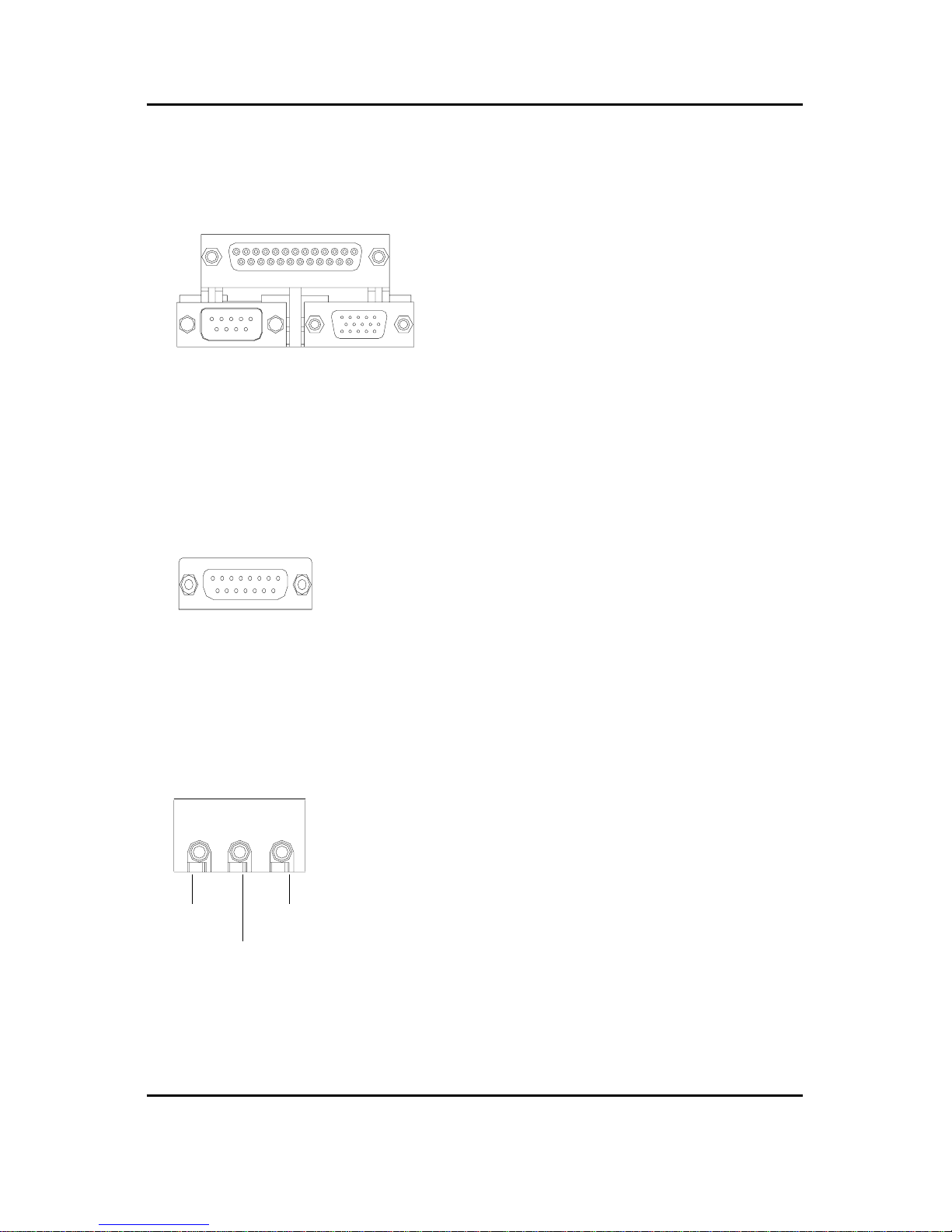
Game /MIDI Ports
Audio Connectors
Thisconnectorsupportsjoystick,MIDIkeyboard
andotherrelateaudiodevices.
Afterinstallonboardaudiodriver, youmay
connectspeakertoLineOutjack,microphoneto
MICInjack.DevicelikeCD-ROM,walkmanetc
canbeconnectedtoLine-Injack.
LineIn
MIC In
LineOut
ParallelPort,SerialPortandVGAPort(LPT/COMA/VGA)
Thisconnectorsupports1standardCOM port
,1Parallelport and1VGAport.Devicelike
printer canbeconnectedtoParallelport;mouse
andmodemetccanbeconnectedtoSerialports.
ParallelPort
(25pinFemale)
COMA VGA
SerialPort
(9pinMale) VGAPort
(15pinFemale)
Joystick/MIDI(15pinFemale)

17
Hardware Installation Process
Step4-2:ConnectorsIntroduction
A) ATXPWR H) USB2
B) JP10 I) BATTERY
C) SYS FAN J) CD_IN
D) Floppy/IDE1/IDE2 K) CPUFAN
E) J7 L) COMB
F) LANWAKEUP M) FRONTAUDIO
G) IR N) USB_VS
A
B
C
D
E
J
L
M
K
F
G
H
I
N
18
GA-6VEM Series Motherboard
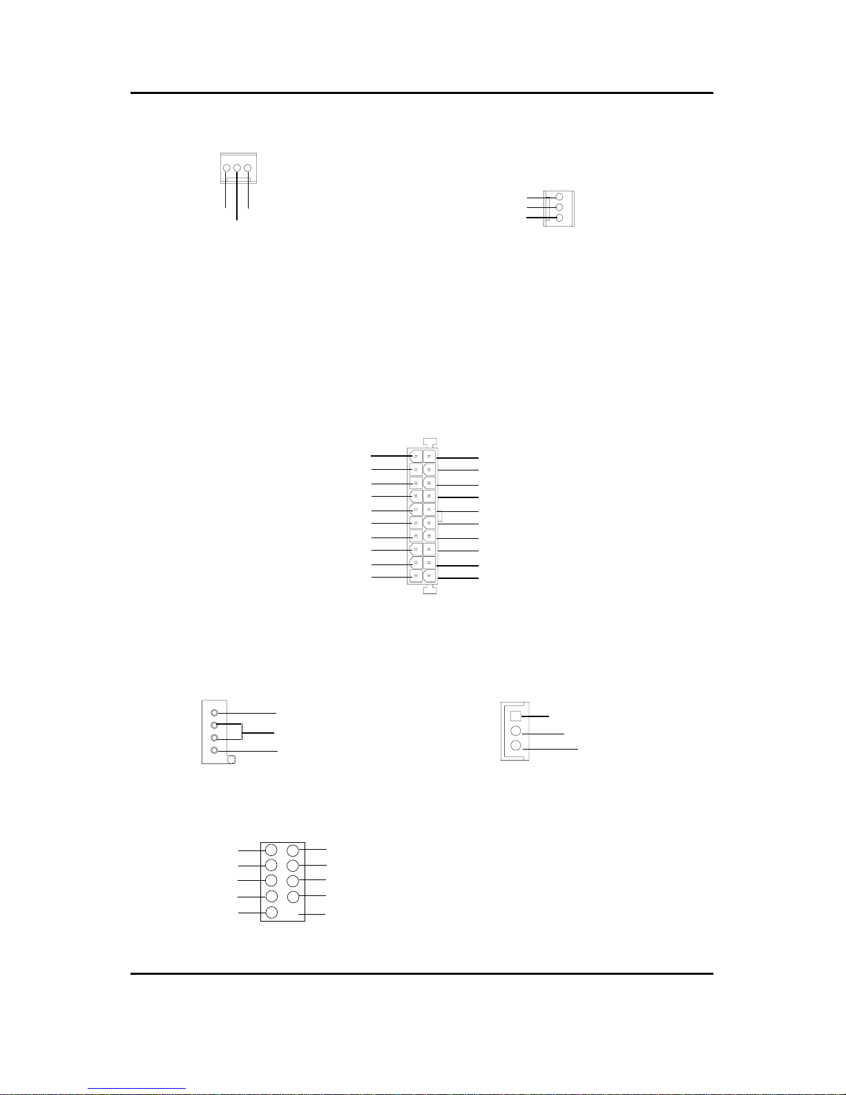
K) CPU_FAN (CPU_FAN Connector)
A) ATXPWR(ATXPower)
PS-ON(SoftOn/Off)
3.3V
3.3V
GND
GND
GND
VCC
VCC
+12V
5V SB (Stand by +5V)
PowerGood
3.3V
GND
GND
GND
GND
VCC
VCC
-12V
1
20
-5V
+12V/Control
GND
Sense
1
F) LAN WAKE UP
C) SYS_FAN (SYS_FAN Connector)
J) CD_IN
L) COMB
1CD-L
CD-R
GND
+12V/Control
Sense
GND
1
TheCPUfanconnectorsupportsMax.current
upto600mA.
ACpowercordshouldonlybeconnectedtoyourpowersupplyunitafterATXpowercableand
otherrelateddevicesarefirmlyconnectedtothemainboard.
+5V SB
GND
Signal
1
DCD2 RXD2
TXD2 DTR2
GND DSR2
RTS2 CTS2
RI2 NC
109
21
19
Hardware Installation Process
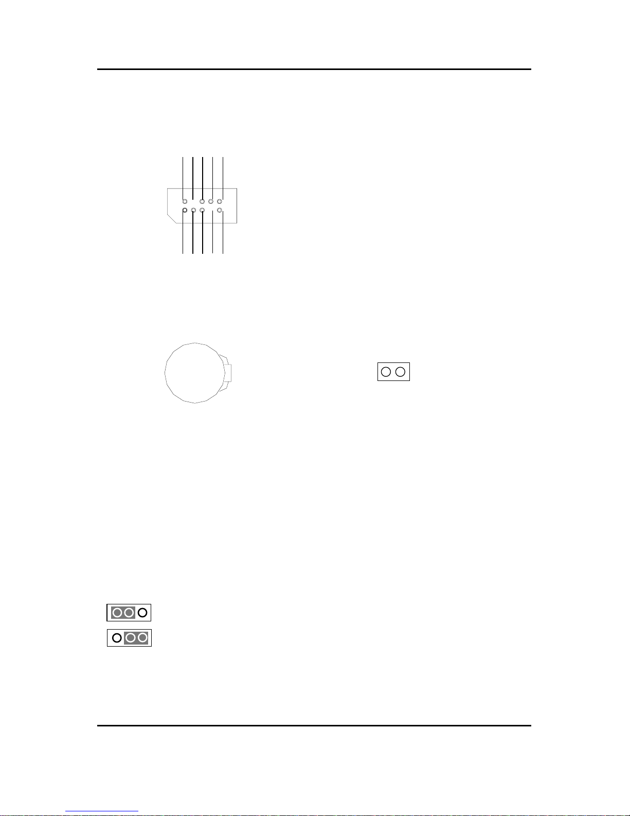
M ) Front Audio Connector
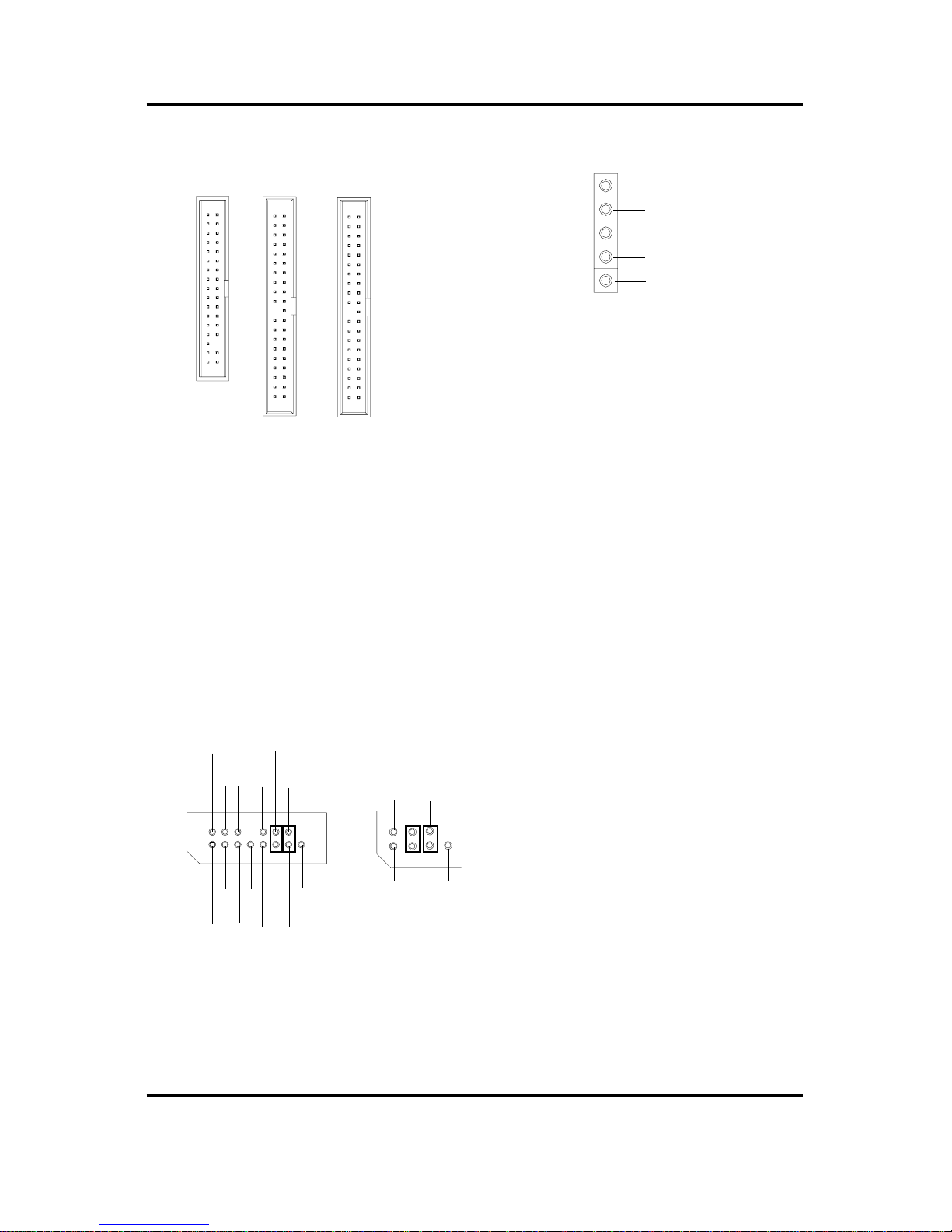
D) Floppy / IDE1 / IDE2
1
Floppy
1
IDE2
1
IDE1
G) IR
BecarefulwiththepolarityoftheIRconnector
whileyouconnecttheIR.Pleasecontactyou
nearestdealerforoptionalIRdevice.
Incasespeaker(L)
GND
GND
GNDRearAudio(R)
RearAudio(L)
Incasespeaker(R)GND
GND
GND
FrontAudio(R)
FrontAudio(L)
+12V
MIC
1
GND
RearAudio(L)
MIC
FrontAudio(R)
GND
1
RearAudio(R)
FrontAudio(L)
Type2
Type1
Therearetwotypesof FrontAudioconnector,pleaserefertothetablesbelowbeforeyouinstall.
Ifyouwanttousetype-1FrontAudio
connector,youmustremove11-12,13-14
Jumper.Ifyouwanttousetype-2FrontAudio
connector,youmustremove3-4,5-6Jumper.
Inordertoutilizethefrontaudioheader,your
chassismusthavefrontaudioconnector.Also
pleasemakesurethepin assigmentonthe
cableisthesameasthepinassigmentonthe
MBheader.Tofindoutifthechassisyouare
buyingsupport frontaudioconnector, please
contactyourdealer.
IRRX
NC
IRTX
GND
VCC
1
20
GA-6VEM Series Motherboard
H) USB2
GND
NC
USB D3+
USB D3-
Power
Power
USB D2-
USB D2+
NC
GND
B) JP10 (STR LED Connector)
Becarefulwiththepolarityofthefront panel
USBconnector.Check thepinassignment
whileyouconnectthefrontpanelUSBcable.
Pleasecontact yournearestdealerforoptional
frontpanelUSBcable.
STRLEDConnector
Donotremovememorymoduleswhile
DIMMLEDison.It mightcauseshortor
otherunexpecteddamagesduetothe
1.8Vstandbyvoltage.Removememory
modulesonlywhenSTRfunctionis
disabledbyjumperandACPowercordis
disconnected.
I) Battery
CAUTION
Dangerofexplosionifbatteryisincorrectly
replaced.
Replaceonlywiththesameorequivalent
typerecommendedbythemanufacturer.
Disposeofusedbatteriesaccordingtothe
manufacturer’sinstructions.
N) USB_VS (PS/2 USB Wake Up selection)
1-2close: Enable(USBWakeup)
2-3close:Normal(Default)
+
1
1
1
This manual suits for next models
1
Table of contents
Other Socket Motherboard manuals


