Socket MB850 User manual

MB850
Socket 478 Pentium 4
Intel 845GVMini ITX
USER’S MANUAL
Version 1.0

ii MB850 User’s Manual
Acknowledgments
Award is a registered trademark of Award Software International,
Inc.
PS/2 is a trademark of International Business Machines
Corporation.
IntelandPentium4are registeredtrademarksof IntelCorporation.
Microsoft Windows is a registered trademark of Microsoft
Corporation.
Winbond is a registered trademark of Winbond Electronics
Corporation.
All other product names or trademarks are properties of their
respective owners.

MB850 User’s Manual iii
Table of Contents
Introduction....................................................... 1
Product Description ..........................................................1
Checklist...........................................................................2
Specifications....................................................................3
Board Dimensions.............................................................4
Installations....................................................... 5
Installing the CPU.............................................................6
Installing the Memory.......................................................7
Setting the Jumpers...........................................................8
Connectors on MB850.....................................................13
Watchdog Timer Configuration.......................................22
Digital I/O Sample Code.................................................26
BIOS Setup....................................................... 30
Drivers Installation...................................... 52
Intel Chipset Software Installation Utility........................53
Intel 845GV Chipset Graphics Driver Installation............56
AC97 Codec Audio Driver Installation............................59
Realtek RTL8139 LAN Drivers Installation .....................61
Appendix........................................................... 64
A. I/O Port Address Map.................................................64
B. Interrupt Request Lines (IRQ) ....................................65

iv MB850 User’s Manual
This page is intentionally left blank.

INTRODUCTION
MB850 User’s Manual 1
Introduction
Product Description
The MB850 Pentium 4 Mini ITX board incorporates the Intel® advanced
845GV Chipset Memory Controller hub and supports 478-pin Intel
Pentium 4 processors of 1.3GHz and up to 3.06GHz+ with FSB
533MHz/400MHz. MB850 supports the Pentium 4 processor with
256-KB L2 cache,Pentium 4 processor with 512-KB L2 cache on 0.13
micron process and Pentium 4 Mobile processor*.
The I/O functions are on MB850 integrated onto the ICH4. It supports the
integrated graphics device (IGD) on the GMCH. The IGD has 3D, 2D, and
video capabilities. The system memory size can be up to 1GB, using the
single DDR socket on board. Four USB ports are supported with the USB
1.1/2.0 standard.
MB850 supports TV out or LVDS with the use of the Chrontel CH7017
display controller device that accepts two digital graphics input data
streams. One data stream outputs through an LVDS transmitter to an
LCD panel, while the other data stream is encoded for NTSC or PAL TV
and outputs through a 10-bit high speed DAC. The TV encoder device
encodes a graphics signal up to 1024x768 resolution and outputs the
video signals according to NTSC or PAL standards. The LVDS
transmitter operates at pixel speeds up to 165MHz per link, supporting
1600x1200 panels at 60Hz refresh rate. MB850, however, supports
either TV out or LVDS interface one at a time.
The MB850 Mini ITX SBC supports CRT VGA interface as well as TV
out or LVDS interface. Realtek LAN 8100BL supports Ethernet
functionality(10/100Mb). The board alsohas AC976CH audio, 4 COM
ports, UDMA 100, 4 USB ports, watchdog timer and a PCI slot for
expandability. Dimensions of the board are 170mm x 170mm.
This board represents the perfect choice for those who want superior
performance for POS, kiosk, ATM, Web payphone, medical and other
embedded applications.
*MB850 for Pentium 4 Mobile processor is available based on quantity orders.
Contact your supplier for details.

INTRODUCTION
2MB850 User’s Manual
Checklist
Your MB850 package should include the items listed below.
•The MB850 P4 embedded board
•This User’s Manual
•1 CD containing chipset drivers and flash memory utility
•Optional cables such as:
•1 slim FDD Ribbon Cable (For MB850F only)
•2 IDE Ribbon Cables (40-pin & 44-pin)
•1 COM Port Cable

INTRODUCTION
MB850 User’s Manual 3
Specifications
Product Name MB850
Form Factor Mini ITX (170mm x 170mm)
CPU Type Socket 478 Intel Pentium 4 or Intel Pentium 4Mobile
CPU Voltage 1.1V~1.75V
System Speed Pentium 4 1.7G~3.06G; P4-M 1.7G~2.2GHz
Front Side Bus Pentium 4 400/533MHz;P4-M 400 MHz 100MHz x 4
Green /APM APM1.2
CPU Socket Socket 478
Chipset
Intel 845GVChipset
GMCH: 82845GV760 pin FC-BGA
ICH4: 82801DB 421 pin BGA
FWH
BIOS Award BIOS Support ACPI Function
Cache 128K/256K/512K Level 2 (CPU integrated)
VGA 82845GVbuilt-in, AGP 4X,support CRT
LVDS
For MB850F Chrontel CH7017, support (24bit or 18bit LVDS LCD
panel)or (TV Out)
LAN Realtek 8100BL 10/100Mb LAN Controller
Memory type
1x DDR 2.5V PC200/266/333 DDR SDRAM
(without
ECC Function) DIMM Module, Max. capacity -1GB
LPC I/O Winbond W83627HF:Parallelx1, COM1, COM2
(RS-232), FDC 1.44MB (Slim), Hardware monitor (3
thermal inputs, 6 voltage monitor inputs, VID0-4, 1
chassis open detection, 2Fan Header)
Digital I/O 4 IN 4 OUT 2X5 Pin header
RTC/CMOS ICH4 Built-in
Battery Lithium Battery
Keyboard / Mouse PS/2 Keyboard and PS/2 Mouse Connectors
D-type connectors PS/2 keyboard/Mouse, VGA (CRT), RJ-45,COM1,
Print, USBx2, Line out, Linein, Mic.
Local bus IDE
(ICH4
built-in) IDE1 40-pin box header (Ultra DMA 33/66/100); IDE2
44-pin header
Secondary I/O Fintek F81216D COM3, 4 (RS232)
Expansion slots PCI slot x 1 (supports 2 Bus master )
Audio ICH4 Built-in Sound controller + AC97 Codec ALC
650 6 Channel (Line-out, Line-in, Mic.)
Power Connector ATX 12V(4 pin)
USB 4 ports, USB 2.0
Watchdog Timer Yes (256 segments: 0,1,2,...255 sec/min)
Power Voltages +5V, +12V, -12V, 5VSB, 3.3V (for MB850)
+5V, +12V (for MB850F)
Other Features Modem Wakeup, LAN Wakeup
Dimensions 170 mm x 170mm

INTRODUCTION
4MB850 User’s Manual
Board Dimensions

INSTALLATIONS
MB850 User’s Manual 5
Installations
This section provides information on how to use the jumpers and
connectors on the MB850 in order to set up a workable system. The
topics covered are:
Installing the CPU...............................................................................6
Installing the Memory.........................................................................7
Setting the Jumpers.............................................................................8
Connectors on MB850 .....................................................................13
Watchdog Timer Configuration.......................................................22
Digital I/O Sample Code...................................................................26

INSTALLATIONS
6MB850 User’s Manual
Installing the CPU
The MB850 embedded board supports a Socket 478 processor socket for
Intel Pentium 4 processors or Pentium 4 Mobile processors.
The Socket 478 processor socket comes with a lever to secure the
processor. Raise this lever to about a 90°angle to allow the insertion of
the processor. Place the processor into the socket by making sure the
notch on the corner of the CPU corresponds with the notch on the inside
of the socket. Once the processor has slide into the socket, return the lever
to the lock position. Refer to the figures below.
After you have installed the processor into the socket, check if the
jumpers for the CPU type and speed are correct.
NOTE:
Ensure that the CPU heat sink and the C
PU top surface are in
total contact to avoid CPU overheating problem that would
cause your system to hang or be unstable.

INSTALLATIONS
MB850 User’s Manual 7
Installing the Memory
The MB850 embedded board supports one DDR memory sockets for a
maximum total memory of 1GB in DDR memory type. The memory
module capacities supported are 128MB, 256MB, 512MB and 1GB. The
following table lists the supported DDR DIMM configurations. Intel
845GV supports configurations defined in the JEDEC DDR DIMM
specification only. Non-JEDEC standard DIMMs such as double-sided
x16 DDR SDRAM DIMMs are not supported.
Installing and Removing Memory Modules
To install the DDR modules, locate the memory slot on the embedded
board and perform the following steps:
1.Hold the DDR module so that the key of the DDR module align with
those on the memory slot.
2.Gently push the DDR module in an upright position until the clips of
the slot close to hold the DDR module in place when the DDR module
touches the bottom of the slot.
3.To remove the DDR module, press the clips with both hands.
DDR Module
Lock
Lock
Lock
Lock

INSTALLATIONS
8MB850 User’s Manual
Setting the Jumpers
Jumpers are used on MB850 to select various settings and features
according to your needs and applications. Contact your supplier if you
have doubts about the best configuration for your needs. The following
lists the connectors on MB850 and their respective functions.
Jumper Locations on MB850.............................................................9
Configuring the CPU Frequency......................................................10
JP4: Keyboard/Mouse Power Setting..............................................10
J8: RTL8100BL LAN Enable/Disable.............................................10
JP16: LVDS Panel Power Select .....................................................10
JP17: Clear CMOS Contents............................................................11
JP11: COM1 RS232 +5V / +12V Power Setting...........................11
JP5: COM2 RS232 +5V / +12V Power Setting.............................11
JP14: COM3 RS232 +5V / +12V Power Setting...........................11
JP13: COM4 RS232 +5V / +12V Power Setting...........................12
JP18: AT or ATX Power Setting......................................................12

INSTALLATIONS
MB850 User’s Manual 9
Jumper Locations on MB850
Jumper on MB850.............................................................Page
Configuring the CPU Frequency..........................................10
JP4: Keyboard/Mouse Power Setting...................................10
J8: RTL8100BL LAN Enable/Disable.................................10
JP16: LVDS Panel Power Select..........................................10
JP17: Clear CMOS Contents................................................11
JP11: COM1 RS232 +5V / +12V Power Setting ...............11
JP5: COM2 RS232 +5V / +12V Power Setting..................11
JP14: COM3 RS232 +5V / +12V Power Setting ...............11
JP13: COM4 RS232 +5V / +12V Power Setting ...............12
JP18: AT or ATX Power Setting ..........................................12
INSTALLATIONS
10 MB850 User’s Manual
Configuring the CPU Frequency
The MB850 embedded board does not provide DIP switches to configure
the processor speed (CPU frequency).
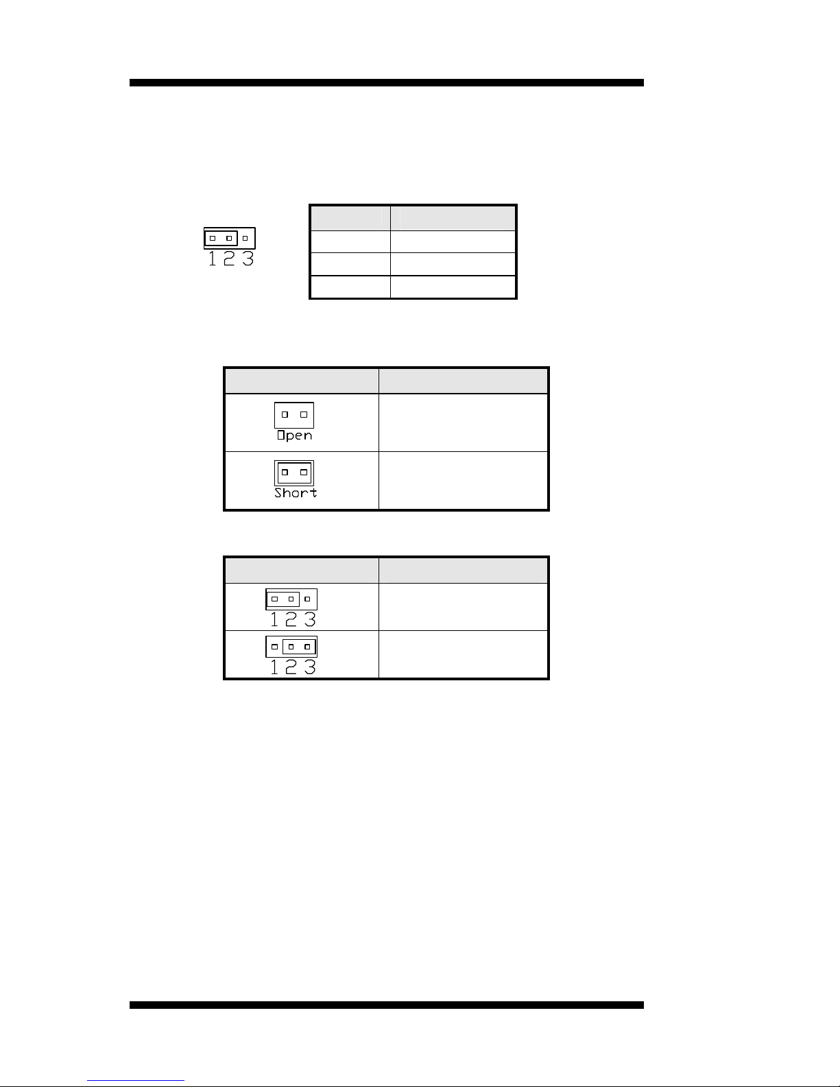
JP4: Keyboard/Mouse Power Setting
Pin # Signal Name
1Vcc
2KB/MS power
3+5VSB
Default: 1-2 short
J8: RTL8100BL LAN Enable/Disable
J8 10/100Mb LAN
Enable
Disable
JP16: LVDS Panel Power Select
JP16LVDS Panel Power
3.3V (default)
5V
[
Note: The LVDS panel resolution can be configured in the BIOS
Setup.

INSTALLATIONS
MB850 User’s Manual 11
JP17: Clear CMOS Contents
Use JP4 to clear the CMOS contents. Note that the ATX-power
connector should be disconnected from the board before clearing
CMOS.
JP17 Setting Function
Pin 1-2
Short/Closed Normal
Pin 2-3
Short/Closed Clear CMOS
JP11: COM1 RS232 +5V / +12V Power Setting
Pin # Signal Name JP11 Signal Name Pin #
1RI +12V 2
3RI (Default) RI (Default) 4
5RI
+5V 6
COM1Settings: Pin 1-2short = +12V, Pin 5-6short = +5V, Pin 3-4
Standard COM Port
JP5: COM2 RS232 +5V / +12V Power Setting
Pin # Signal Name JP2 Signal Name Pin #
1RI +12V 2
3RI (Default) RI (Default) 4
5RI
+5V 6
COM2Settings: Pin 1-2short = +12V, Pin 5-6short = +5V, Pin 3-4
Standard COM Port
JP14: COM3 RS232 +5V / +12V Power Setting
Pin # Signal Name JP14Signal Name Pin #
1RI +12V 2
3RI (Default) RI (Default) 4
5RI
+5V 6
COM3Settings: Pin 1-2short = +12V, Pin 5-6short = +5V, Pin 3-4
Standard COM Port

INSTALLATIONS
12 MB850 User’s Manual
JP13: COM4 RS232 +5V / +12V Power Setting
Pin #Signal Name JP13Signal Name Pin #
1RI +12V 2
3RI (Default) RI (Default) 4
5RI
+5V 6
COM4Settings: Pin 1-2short = +12V, Pin 6-5 short = +5V, Pin 3-4
Standard COM Port
JP18: AT or ATX Power Setting
JP18 Setting Function
Pin 1-2
Short/Closed ATX Power (Default)
Pin 2-3
Short/Closed AT Power

INSTALLATIONS
MB850 User’s Manual 13
Connectors on MB850
The connectors on MB850 allows you to connect external devices such as
keyboard, floppy disk drives, hard disk drives, printers, etc. The following
table lists the connectors on MB850 and their respective functions.
Connector Locations on MB850......................................................14
JV1, JP15: TV out Connector (RCA Jack and 3-pin Header)........15
J1: ATX 12V/+12V Power Connector............................................15
J2: ATX Power Supply Connector...................................................15
J3: External PS/2 Keyboard Connector...........................................16
J4: IrDA Connector...........................................................................16
CN5: Serial Ports..............................................................................16
FDD1: Floppy Drive Connector ......................................................17
IDE1, IDE2: EIDE Connectors........................................................17
FAN1, FAN3: System Fan Power Connector .................................18
FAN2: CPU Fan Power Connector .................................................18
J9, J7: LVDS Connectors (1st channel, 2nd channel).....................19
J10: USB Connectors .......................................................................19
J11: System Function Connector.....................................................19
J12: Panel Inverter Power Connector..............................................20
J13: CD-In Audio Connector...........................................................20
J14: Wake On LAN Connector ........................................................20
CN2: Digital 4-in 4-out I/O Connector...........................................20
CN6: RJ45 Connector......................................................................21
CN7: External Audio Connector......................................................21
CN8: Line Out, Line In, Mic Connector..........................................21

INSTALLATIONS
14 MB850 User’s Manual
Connector Locations on MB850
Connector on MB850.....................................................................................................Page
JV1, JP15: TV out Connector (RCA Jack and 3-pin Header)................................................15
J1: ATX 12V/+12V Power Connector.................................................................................15
J2: ATX Power Supply Connector.......................................................................................15
J3: External PS/2 Keyboard Connector................................................................................15
J4: IrDA Connector............................................................................................................16
CN5: Serial Ports...............................................................................................................16
IDE1, IDE2: EIDE Connectors...........................................................................................17
FDD1: Floppy Drive Connector...........................................................................................17
FAN1, FAN3: System Fan Power Connector.......................................................................18
FAN2: CPU Fan Power Connector.....................................................................................18
J9, J7: LVDS Connectors (1st channel, 2nd channel) ............................................................19
J10: USB Connectors.........................................................................................................19
J11: System Function Connector..........................................................................................19
J12: Panel Inverter Power Connector ..................................................................................20
J14: Wake On LAN Connector...........................................................................................20
J13: CD-In Audio Connector...............................................................................................20
CN7: External Audio Connector..........................................................................................20
CN8: J7: Line Out, Line In, Mic Connector ..........................................................................22
CN2: Digital 4-in 4-out I/O Connector .................................................................................22

INSTALLATIONS
MB850 User’s Manual 15
JV1, JP15: TV out Connector (RCA Jack and 3-pin Header)
The locations of the TV out connector are as below:
J1: ATX 12V/+12V Power Connector
Pin # Signal Name
1Ground
2Ground
3+12V
4+12V
J2: ATX Power Supply Connector
Signal Name Pin # Pin # Signal Name
3.3V 11 13.3V
-12V 12 23.3V
Ground 13 3Ground
PS-ON 14 4+5V
Ground 15 5Ground
Ground 16 6+5V
Ground 17 7Ground
-5V 18 8Power good
+5V 19 95VSB
+5V 20 10 +12V
11 1
20 10

INSTALLATIONS
16 MB850 User’s Manual
J3: External PS/2 Keyboard Connector
J3,a 6-pin header connector, has functions for external keyboard.
Signal Name Pin #
Vcc 1
Internal KB CLK 2
External KB CLK 3
Internal KB data 4
External KB data 5
Ground 6
Default: 2-3 short, 4-5 short for internal CN1 keyboard
For external keyboard, use 1, 3, 5, 6 pin
J4: IrDA Connector
J4is used for an optional IrDA connector for wireless communication.
Pin # Signal Name
1+5V
2No connect
3Ir RX
4Ground
5Ir TX
CN5: Serial Ports
Pin # Signal Name (RS-232)
1DCD, Data carrier detect
2RXD, Receive data
3TXD, Transmit data
4DTR, Data terminal ready
5Ground
6DSR, Data set ready
7RTS, Request to send
8CTS, Clear to send
9RI, Ring indicator
10 No Connect.
Table of contents
Other Socket Motherboard manuals


