Socket PGA370 User manual

ILA
Socket PGA370 Mainboard
User's Manual
Model : ILA
Manual version : English, version 1.0
Release Date : January 4, 1999

II
Copyright
Copyright 1999 by this company. All rights reserved.
No part of this publication may be reproduced, transmitted, transcribed,
stored in a retrieval system, or translated into any language in any form or by
any means, electronic, mechanical, magnetic, optical, manual or otherwise,
without the prior written consent of the copyright holders.
User’s Notice
The contents of this publication are subject to change. This company reserves
the right to alter the contents of this publication at any time and without
notice. The contents of this publication may contain inaccuracies or
typographical errors and is supplied for informational use only.
Intel and Pentium are registered trademarks of Intel Corporation.
OS/2 and IBM are registered trademarks of International Business Machines.
Windows and MS-DOS are registered trademarks of Microsoft Corporation.
AWARD is a registered trademark of Award Software Inc.
Other brand, corporate, and product names may or may not be registered
trademarks or copyright of their respective companies.
III
FCC & DOC Compliance
Federal Communications Commission Statement
This device complies with FCC Rules Part 15. Operation is subject to the
following two conditions:
²This device may not cause harmful interference, and
²This device must accept any interference received, including
interference that may cause undesired operation.
This equipment has been tested and found to comply with the limits for a
Class B digital device, pursuant to Part 15 of the FCC Rules. These limits are
designed to provide reasonable protection against harmful interference in a
residential installation. This equipment generates, uses and can radiate radio
frequency energy and, if not installed and used in accordance with the
manufacturer
communication. However, there is no guarantee that interference will not
occur in a particular installation. If this equipment does cause harmful
interference to radio or television reception, which can be determined by
turning the equipment off and on, the user is encouraged to try to correct the
interference by one or more of the following measures:
²Re-orient or relocate the receiving antenna.
²Increase the separation between the equipment and the receiver.
²Connect the equipment to an outlet on a circuit different from that to
which the receiver is connected.
²Consult the dealer or an experienced radio/TV technician for help.
Warning! The use of shielded cables for the connection of the monitor to
the graphics card is required to assure compliance with FCC regulations
Changes or modifications to this authority to operate this equipment.

IV
CONTENTS
SECTION 1: PRODUCT INFORMATION
1-1 Manual Features……………………………………………………..….…...1-1
1-2 Package Check List....................…………………………1-1
1-3 Mainboard Specification...…….…………………………………1-2
1-4 Mainboard Layout ……………………………………………………………..1-6
SECTION 2: HARDWARE INSTALLATION
2-1 Jumper Settings.........................................2-1
2-1.1 CMOS Clear Setting ………..............……………………...2-1
2-1.2 CPU Type Setting …………………......................……..…..2-2
2-1.3 Power Supply Type ……………….......................……..…...2-2
2-2 Connectors ……….……....…………….………………………………........2-3
2-2.1 Panel Connector……….…...………………………………..……………2-3
2-2.2 AT Power Connector………………………………....………………2-4
2-2.3 ATX Power Connector…………………………………..…………..2-4
2-2.4 Fan Connectors…….……..……………………………………….…………2-5
2-2.5 PS/2 Mouse Connector…………………………..……..…………2-5
2-2.6 Keyboard Connector….……………………………..…..……………2-6
2-2.7 Serial Device(COM1/COM2) Connectors….2-6

V
2-2.8 Printer Connector.………………………………………………..…..2-7
2-2.9 Floppy Drive Connector…….….….……...................….…2-7
2-2.10 IDE Hard Disk and CD-ROM Connector..…….…….……2-8
2-2.11 IrDA Connector…….….………………………........………2-9
2-2.12 Wake On LAN Connector….….….……....…....……….…2-9
2-3 System Memory Installation .......……………...2-10
2-3.1 Type .............………………………….........….……….…2-10
2-3.2 Speed ..……….………………………………………….…2-10
2-3.3 Buffered and Non-buffered ..……..........….....….….……2-11
2-3.4 2-clock and 4-clock Signal….……..….…...………...……2-11
2-3.5 Parity and Non-parity………....……...………….......……2-11
2-3.6 Memory Auto detection by BIOS …....….…………….…2-11
2-3.7 Suggested SDRAM combination ….........…...……….…2-12
2-4 Game/Audio Connector……………………………………………2-12
SECTION 3: CMOS SETUP UTILITY
3-1 BIOS Setup Main Menu..............................3-1
3-2 Standard CMOS Setup...............................3-2
3-3 BIOS Features Setup .................................3-5
3-4 Chipset Features Setup...........................3-10
3-5 Power Management Setup.......................3-15
3-6 PNP/PCI Configuration Setup .................3-21
3-7 Load Setup Defaults ................................3-25
3-8 Load Turbo Defaults................................3-26
3-9 Integrated Peripherals .............................3-27

VI
3-10 Password Setting………................…..………………..…3-32
3-11 IDE HDD Auto Detection…....….…..……………………….3-33
3-12 Save & Exit Setup………..........….….…………………………..3-33
3-13 Exit without Saving……..……......….……………………….….3-33
SECTION 4: BIOS/SOFTWARE UTILITY
4-1 Flash Utility Maxflash.exe..........................4-1
4-2 BIOS Flash/Upgrade Protection ......…….…....4-2
4-3 Remove Question Marks "?" in Win95
Device Manager……………………………………………………………….....4-2
4-4 Install Bus Master IDE (Ultra DMA/33)
Driver ………………………………......…………………………………………...…...4-3
SECTION 5: AUDIO DRIVER/UTILITY
5-1 Windows 95/98 Driver Installation………….…..5-1
5-2 Windows NT Driver Installation…………………....5-4
5-3 DOS/Windows 3.1 Driver Installation…….…5-5
5-4 OS/2 Driver Installation………………………………………..….5-5

ILA USER’S MANUAL 1-1
SECTION 1.
PRODUCT INFORMATION
Thanks for purchasing ILA Socket PGA370 mainboard.
This user’s manual contains all the information and features that show you
how to use the ILA mainboard. Please take a moment to familiarize
yourself with the design and organization of this manual.
1-1 Manual Features
This manual is divided into the following four sections:
Section 1: Product Information
A brief overview of what comes in the mainboard package, the mainboard
layout and the specification it appears.
Section 2: Hardware Installation
Tell you the usage of the mainboard jumpers and the connectors.
Section 3: CMOS Setup Utility
A summary of the mainboard CMOS (BIOS) Setting.
Section 4: BIOS/Software Utility
Introduction of some useful mainboard’s BIOS/Software utility.
Section 5: Audio Driver/Utility
Install Audio Driver & Utility
I. PRODUCT INFORMATION
1-2ILA USER’S MANUAL
1-2 Package Check List
This ILA mainboard package contains the following items. Please inspect
the package contents and confirm that everything is there. If anything is
missing or damaged, call your vendor for instructions before operating.
The package includes:
lOne ILA Mainboard
lOne Floppy Interface Cable
lOne IDE Interface Cable
lOne Audio Interface Cable
lOne CD Title including Bus Master IDE Driver and Utilities
lOne User’s Manual
lOne serial port bracket
lOne parallel port & PS/2 Mouse bracket
1-3 Mainboard Specification
Form Factor lAT form factor
Board Size l220 mm x 220 mm
CPU lSupports Socket PGA370 Celeron CPU up to
433MHz
System Memory lFor LX mainboard, DIMM 168-pin x 3 , SDRAM
added maximum up to 384MB
lFor EX mainboard, DIMM 168-pin x 2 , SDRAM
added maximum up to 256MB
lSupports 64M-bit SDRAM technology
Chipset lIntel 440LX/EX AGP Chipset
System Bus/FSB l66MHz
l68.5/75/83.3MHz (Available for over-clocking)
I. PRODUCT INFORMATION
ILA USER’S MANUAL 1-
3
Expansion Slots l1 x AGP bus
l2 x ISA bus
l3 x PCI bus with Bus master/slave mode
Serial Port lTwo serial ports UART 16550 compatible
lSets serial port 2 to operate in normal mode , IrDA or
ASKIR
Parallel Port One parallel port supports :
lSPP-standard parallel port
lEPP-enhanced parallel port
lECP-extended capabilities port
Floppy Interface Supports drives inches/format with:
l3.5 inches—720KB/1.44MB/2.88MB
l5.25 inches—360KB/1.2MB
IDE Interface lDual PCI IDE interface support up to 4 x IDE HDD or
CDROM
lSupports PIO mode4 , DMA mode2 and Ultra DMA33
USB Interface lTwo USB ports supported
lUSB legacy keyboard function supported
PS/2 Mouse lPS/2 mouse supported
Keyboard lAT keyboard supported
Fuse lSupports recoverable fuse for USB and KB/Mouse
RTC and Battery lRTC build in chipset (south bridge PIIX4)
lLithium (CR-2032) battery
Wake Up Function /
Power On function
lModem ring wake up
lLAN wake up
lRTC Alarm wake up
lKeyboard/ PS/2 Mouse power on
Synchronous
Switching Regulator
lHigh efficient synchronous switching regulator for
CPU core voltage automatically detected
lSupports over-voltage / over-current protection
function

I. PRODUCT INFORMATION
1-4ILA USER’S MANUAL
Hardware Monitor
(Optional)
lFan speed monitor—Two fan connectors , warning
when CPU or Housing fan is malfunction
lFan speed control—Control CPU or Housing fan
speed for the thermal issue
lVoltage monitor—Warning when system voltage
(5V,12V,3.3V,VCORE) are abnormal
lCPU and system thermal monitor—Warning when
CPU and system temperature is higher than a
predefined value
Sound Function lIntegrated OPTi 82C933 sound controller compatible
with:
-Sound Blaster Pro
-Adlib
-Microsoft Windows System
Power Function lSupports ATX (20-pin) power connector
lSupports AT (12-pin) power connector
BIOS lAward BIOS
lYear 2000 Compliance
lPCI 2.1 Compliance
lPnP BIOS v1.0a Compliance
lAPM v1.2 Compliance
lDMI 2.0 compliance
lFlash/Upgrade BIOS protection
lSupports ACPI (Advanced Configuration and Power
Interface) and OS Directed Power Management
lSupports SOFT power
lAnti-Virus Protection supported
lFloppy drive swapping function supported
LED Indicator lSystem power LED
lHDD activity LED
lSystem Suspend LED (Blanking)
Other lAuto-detect AT/ATX power supply type
lSupport third Fan connector (2-pin)

I. PRODUCT INFORMATION
ILA USER’S MANUAL 1-
5
lSupport CIR (Consumer IR) Function

I. PRODUCT INFORMATION
1-6ILA USER’S MANUAL
1-4 Mainboard Layout

I. PRODUCT INFORMATION
ILA USER’S MANUAL 1-
7
Jumpers
1. JP2 Keyboard/PS/2 Mouse Power On
(For ATX Power Supply Only)
4. JP6 Clear CMOS (Real Time Clock)
Expansion Sockets
1. DIMM 1
2. DIMM 2
3. DIMM 3
Support 168-pin DIMM Memory
Support 168-pin DIMM Memory
Support 168-pin DIMM Memory
Expansion Slots
1. CPU Socket-370 CPU Socket PGA370 for supporting Celeron CPU
2. ISA Slot 1 & Slot 2 16-bit ISA Bus Expansion Slot
3. PCI Slot 1 to Slot 3 32-bit PCI Bus Expansion Slot
Connectors
1. KB AT Keyboard Connector (6-pin female)
2. PS/2 Mouse PS/2 Mouse Connector (6-pin female)
3. USB Universal Serial Bus Port 1 and Port 2
(two 4-pin female)
4. COM1/COM2 Serial Port 1 / Serial Port 2 (two 9-pin female)
5. PRINTER Printer (Parallel) Port Connector (25-pin female)
6. ATX POWER ATX Mainboard Power Connector (20-pin block)
7. AT POWER Baby AT Mainboard Power Connector
8. CPUFAN Socket-370 CPU Fan Connector (3 pins)
9. CHAFAN Chassis Fan Connector (3 pins)
10. Floppy Floppy Drive Connector (34 pins)
11. Primary IDE Primary IDE Connector (40 pins)
12. Secondary IDE Secondary IDE Connector (40 pins)
13. IR
14. Wake on LAN Infrared Port Connector (5 pins)
LAN wake up connector

I. PRODUCT INFORMATION
1-8ILA USER’S MANUAL
15. CD Audio In CD Audio In Connector
16. Panel:
- PWR LED Power LED Connector (3 pins)
- KBLCK Keyboard Lock Switch Connector (2 pins)
- SLP Suspend Switch Connector (2 pins)
- SPEAKER Chassis Speaker Connector (4 pins)
- GRN LED Green Status LED Connector (3 pins)
- HDD LED HDD LED Connector (4 pins)
-RESET
-PWR ON Reset Switch Connector (2 pins)
ATX Power Switch Connector (2 pins)
ILA USER'S MANUAL 2-1
SECTION 2.
HARDWARE INSTALLATION
This section gives you a step-by-step procedure on how to install your
system. Follow each section accordingly.
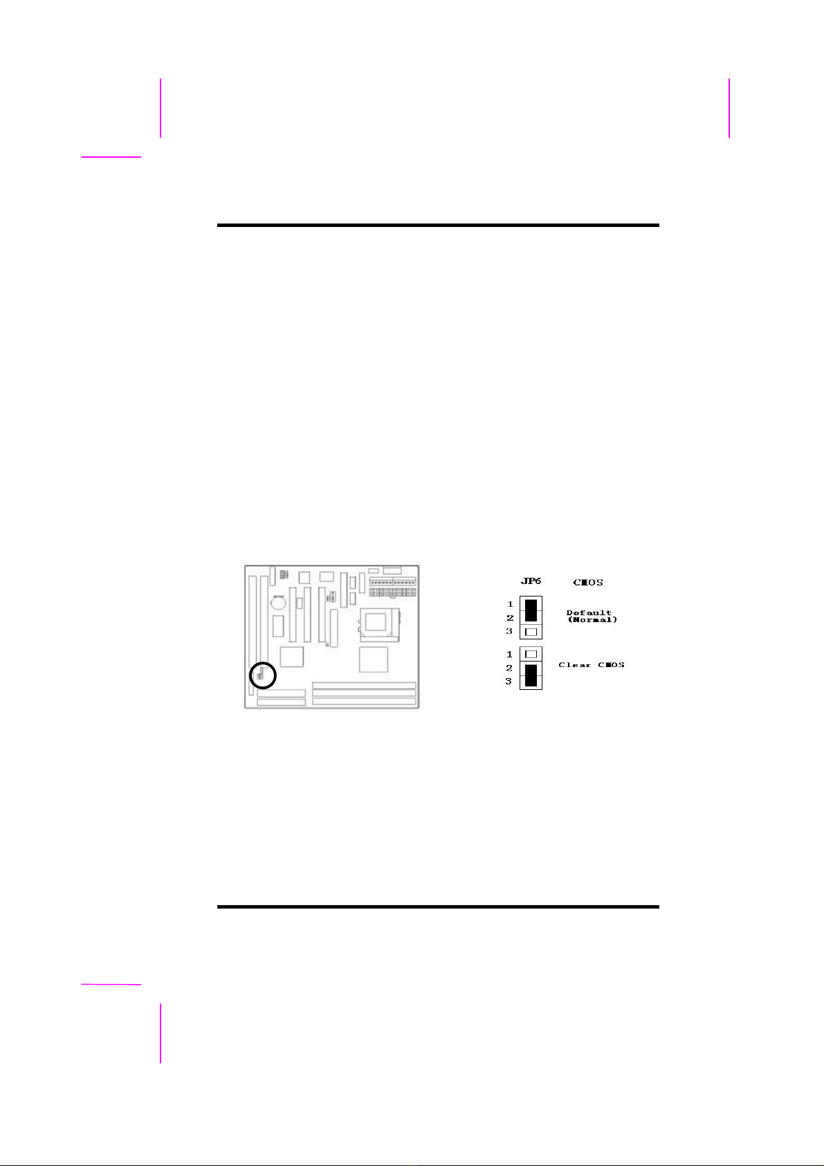
2-1 Jumper Settings
Please refer the following figures for the locations of the jumpers on the
mainboard.
2-1.1 CMOS Clear Setting
To clear CMOS, please follow the steps below:
1. Power off the system and unplug the chassis AC power cord.
2. Short JP6 at pin 2-3 for few seconds.
3. Set JP6 back to its Normal position at pin 1-2.
4. Plug the AC power cord to the chassis.
5. Power on the system and load the BIOS setup default.

II.HARDWARE INSTALLATION
2-2ILA USER’S MANUAL
2-1.2 CPU Type Setting
Auto CPU Type Setting:
This mainboard supports jumperless CPU type setting, no jumper or switch is
needed. The CPU Clock Radio of socket PGA370 Celeron CPU is fix (locked),
all you need to do for CPU Type setting is load “BIOS Setup Defaults”values
to set CPU Clock Frequency at default 66MHz. Then the CPU Type will be
automatically detected by BIOS.
Manual CPU Type Setting:
This mainboard also supports CPU over-clocking by adjusting the CPU Clock
Frequency under “CHIPSET FEATURES SETUP”IN bios Setup.
System Frequency = CPU Clock Radio x CPU Clock Frequency
The available CPU Clock Frequency setting are: 66/68.5/75.0/83.3MHz
Warning: Normally, Intel 440EX/LX Chipset supports 66MHz CPU Clock
Frequency, the other CPU Clock Frequency 75.0/83.3MHz are available only
for internal test or end-user over-clocking testing, which may cause your
system unstable or serious damage.
2-1.3 Power Supply Type
The mainboard supports two kinds of system power supply, AT (P8&P9) and
ATX. For AT power supply, set JP2 at pin 2-3 to use power switch/button to
power on your system. For power supply, set JP2 at pin1-2 and you can
enable or disable KB/PS/2 mouse power on under BIOS Setup/Integrated

II.HARDWARE INSTALLATION
ILA USER'S MANUAL 2-3
Peripherals. If you want to use the “Keyboard Power On”function, make sure
you have a 300mA/+5vSB or above ATX power supply and the supporting
mainboard BIOS.
2-2 Connectors
2-2.1 Panel Connector
- PWR LED ATX Power LED Connector (3 pins)
- KBLCK Keyboard Lock Switch Connector (2 pins)
- SLP Suspend Switch Connector (2 pins)
- SPEAKER Chassis Speaker Connector (4 pins)
- GRN LED Green Status LED Connector (3 pins)
- HDD LED HDD LED Connector (4 pins)
- RESET Reset Switch Connector (2 pins)
II.HARDWARE INSTALLATION
2-4ILA USER’S MANUAL
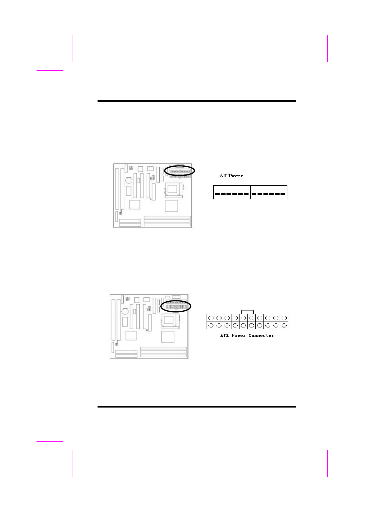
2-2.2 AT Power Connector
Connect the 12-pin AT power supply cable to this power connector. Make sure
the right plug-in direction and the power supply is off before connecting or
disconnecting the power cable.
2-2.3 ATX Power Connector
Connect the 20-pin ATX power supply cable to this power connector. Make
sure the right plug-in direction and the power supply is off before connecting
or disconnecting the power cable.
II.HARDWARE INSTALLATION
ILA USER'S MANUAL 2-5
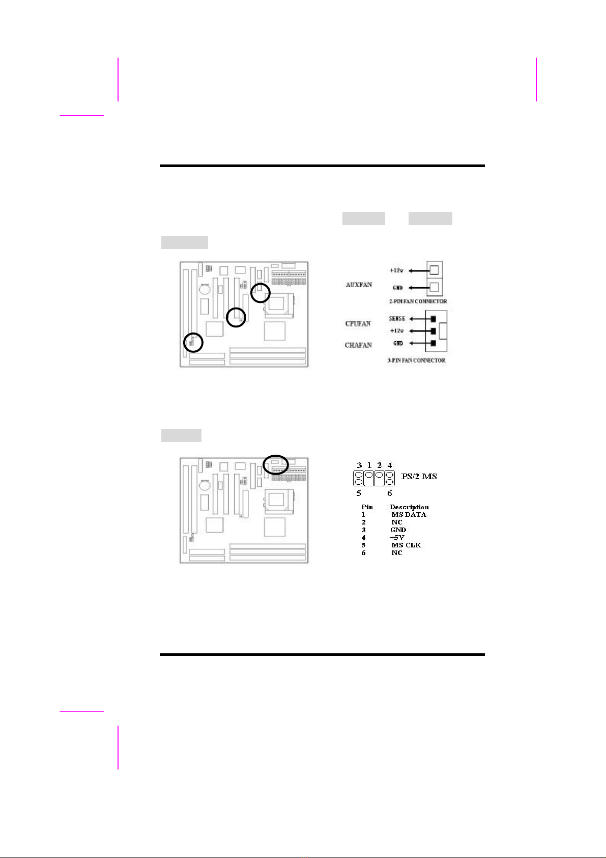
2-2.4 Fan Connectors
Connect the CPU and Chassis Fan cables to the 3-pin fan connectors shown
below. The fan connectors are marked as CPUFAN and CHAFAN on the
mainboard. Connect Auxiliary Fan cable to the 2-pin fan connector marked as
AUXFAN.
2-2.5 PS/2 Mouse Connector
Connect the PS/2 mouse to the onboard 6-pin Mini-Din connector marked as
PS/2 MS.
II.HARDWARE INSTALLATION
2-6ILA USER’S MANUAL
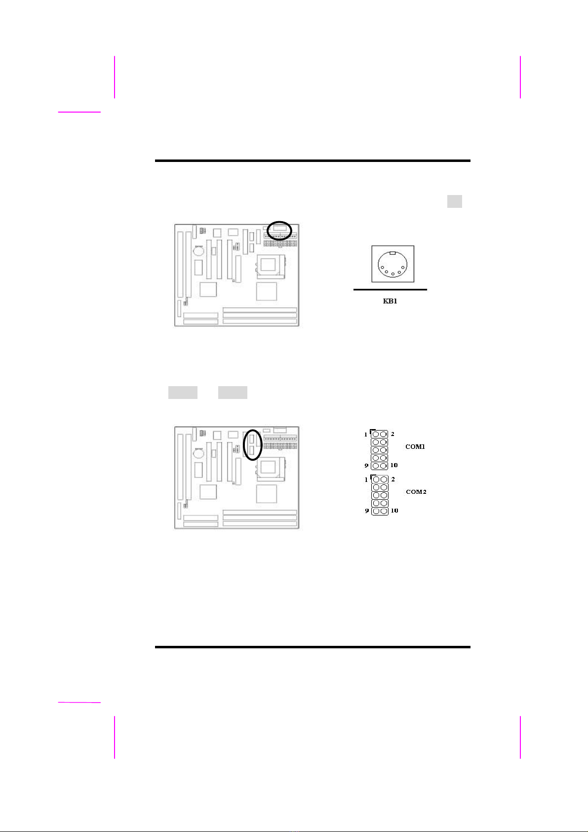
2-2.6 Keyboard Connector
Connect the AT keyboard to the onboard keyboard connector marked as KB.
2-2.7 Serial Device(COM1/COM2) Connectors
Connect your serial device(s) to the onboard 9-pin serial connectors marked
as COM1 and COM2.
This manual suits for next models
1
Table of contents
Other Socket Motherboard manuals


Popular Motherboard manuals by other brands


PC Partner
PC Partner 35895100 Series Technical reference booklet

Advantech
Advantech AIMB-308 Startup manual

MSI
MSI H310M GAMING ARCTIC user guide

Arbor Technology
Arbor Technology EmCORE-i77M3 Quick installation guide

Supermicro
Supermicro B4SC1-CPU user manual

Terasic
Terasic HAN Pilot Platform Hardware manual