Sofi SP8 Series User manual

Sofei Technology
SP8serial programmer
manual
Shenzhen Shuofei Technology Co., Ltd.
SOFI TECHNOLOGY CO.,LTD.
TEL: 0755 - 8486 7757
FAX: 0755 - 8486 7941
WEB:http://www.sofi-tech.com/
Publication Release Date: 2018-07
Revision B4
Description: This manual applies toFlyPROsoftwareV4.40or above
Before using the programmer, please read this manual carefully, and operate the programmer correctly as required. Failure to operate the programmer as required will result in damage to the
programmer and no warranty service!
Translated from Chinese (Simplified) to English - www.onlinedoctranslator.com

Sofei Technology manual
SP8 series programmer
target record
Chapter One product description-------------------------------------------------- -------------------------------------------------- ---------------------
Features------------------------------------------------ -------------------------------------------------- ----------------------- SP8Series
function comparison table --------------------------------------------- -------------------------------------------------- --------
programmer hardware-------------------------------------------------- -------------------------------------------------- ------------------5
quick to use-------------------------------------------------- -------------------------------------------------- ---------------------7 Offline
burning-------------------------------------------------- -------------------------------------------------- ---------------------11 Download
offline data -------------------------------------------------------- -------------------------------------------------- ------------------11 Run
Offline - Manual Mode-------------------------------------------- -------------------------------------------------- --------12 Offline
operation - automatic control mode --------------------------------------- -------------------------------------------------- ---12
Offline working mode status indicator --------------------------------------- -------------------------------------------------- -----12
Offline Data View---------------------------------------------- -------------------------------------------------- -------------------13 ISP
Mode burning-------------------------------------------------- -------------------------------------------------- -------------14 ISPs
interface------------------------------------------------- -------------------------------------------------- ---------------------14 ISPs
Connection line ------------------------------------------------ -------------------------------------------------- -------------------14 Target
chip connection--------------------------------------------------------- -------------------------------------------------- ---------------- ISP
Power Mode------------------------------------------------ -------------------------------------------------- --------------- common
problem--------------------------------------------------- -------------------------------------------------- --------------------17 Disclaimer
-------------------------------------------------- -------------------------------------------------- ---------------------19 file revision log
information-------------------------------------------------- -------------------------------------------------- --------20
3
3
4
Chapter two
third chapter
Chapter Four
chapter Five
15
16
Appendix I
Appendix II
Appendix III
Shenzhen Shuofei Technology Co., Ltd.2

Sofei Technology manual
SP8 series programmer
Chapter 1 Product Introduction
Features
⚫USBPower supply and communication without external power supply. Small size, easy to carry.
⚫Specifically designed for serial memory, it is faster and more stable than general-purpose programmers.
⚫support93/24/25Series memory, support software upgrade to add support for new chips.
⚫Supports poor pin contact detection, effectively improving programming reliability.
⚫standard40Foot zero insertion force locking seat, wide and narrow chips and universal adapters can be used.
⚫The overcurrent protection function can effectively prevent the impact of chip placement errors or bad chips on the programmer.
⚫supportISPMode programming, for the onboard SMD chip, it can be directly wired and programmed.
⚫The programmer has a built-in high-speed processor, which provides high-speed programming and precise timing.
⚫Can be run offline(Note1), without connecting to a computer. built-in128Mbitdata storage.
⚫Mass production programming mode, which automatically detects chip placement and starts programming operations.
⚫support25seriesSPI FLASHChip model detection.
⚫Buzzer sound indicates success or failure.
⚫Support low voltage (3.3V)and5Vchip.
⚫Provides device self-check function.
⚫supportWinXP(SP2),VISTA, Win7, Win8, Win10(32bit/64bit).
Note1: ISPMode does not support offline burning
Shenzhen Shuofei Technology Co., Ltd.3
Sofei Technology manual
SP8 series programmer
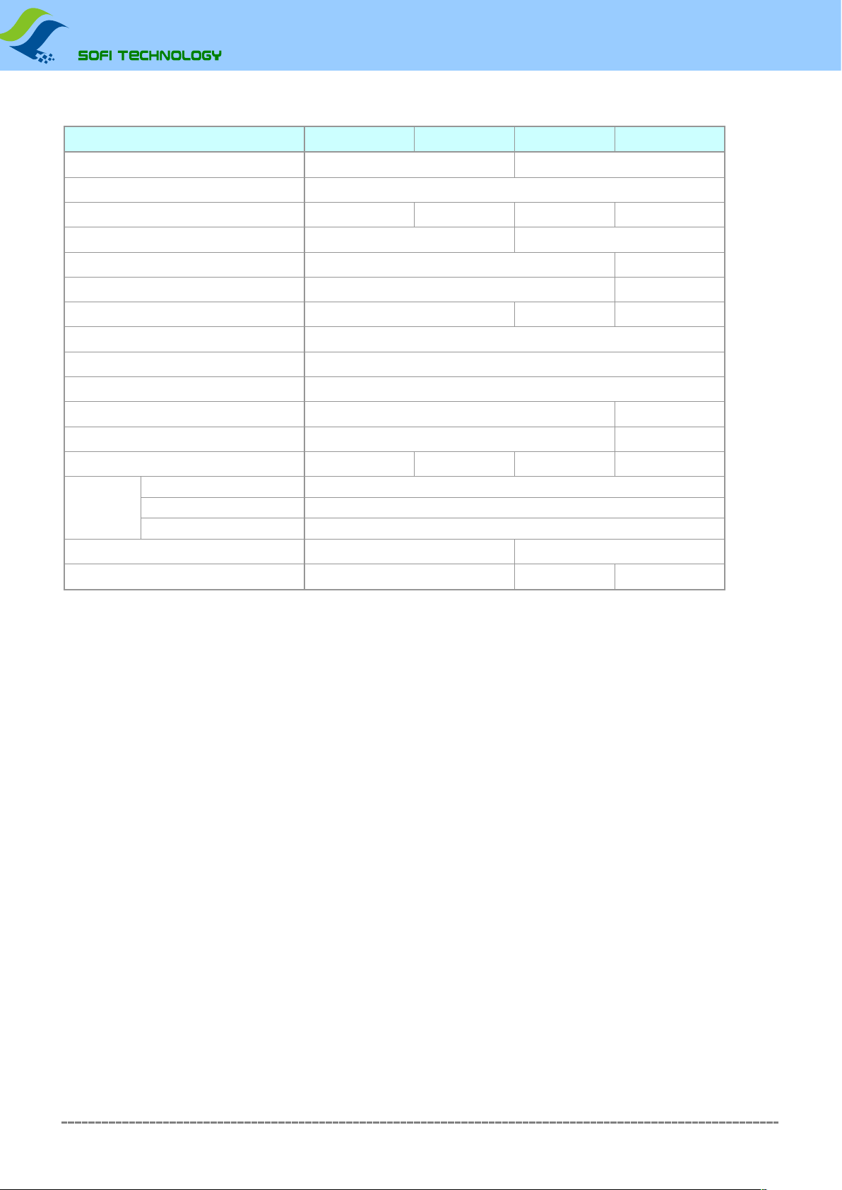
SP8Series function comparison table
Product number:SP8-FX SP8-F SP8-B SP8-A
Support chip maximum capacity(Note1)512Mb(online)/128Mb(offline)512Mb
Support chip voltage 3.3V/5V
Offline burning Y Y N N
Built-in memory (save offline data)128Mb -
Online mass production Y(Automatic detection of chip placement/removal)N
automatic serial number Y(Online burning mode only)N
Buzzer prompt Y(offline mode only)N N
Overcurrent/Short Circuit Protection Y
Lock seat type Domestic gold-plated
ISPburn(Note2)part93/25Series (clock not adjustable)
OTParea read and write(Note2)support not support
Chip configuration(Note2)support not support
Automatic burning machine support (ATE)YN N N
GD25Q16(SOP8) P+V=7.9S
Burning speed
(Note3)
W25Q128FV(SOP8) P+V=60S
MX25L12845E(SOP16) P+V=130S
Offline data download speed 216S@128Mb -
Number of supported chips(Note4)7874 7804 6401
Note 1: SP8Series offline operations support up to128Mbit.
Note 2:Depending on software capabilities, not all chips are supported.
Note 3:The burning speed adopts100%random numbers for testing,Pfor programming,VFor verification; Offline time only applies to products that support the Offline function;
The burning time is for reference only.
Note 4:Number of chips based on software versionV4.06(2016-03-12),Chips will be continuously upgraded, and the numbers in the table are for reference only.
Shenzhen Shuofei Technology Co., Ltd.4

Sofei Technology manual
SP8 series programmer
Chapter 2 Programmer Hardware
Lock seat
Power Indicator (PWR)
Status Indicator (STA)
USB interface
ISP/ATE interface
⚫Lock seat
Used to place chips (including chip adapters/adapters).
Please do not operate the chip that has been soldered on the circuit board through the connection method on the locking seat. The peripheral circuit on the board will cause the operation to fail, and the
programmer will be damaged in severe cases.
Typical Chip Placement Diagram
Pin 1
The placement of other chips (including adapter information) can be found inFlyPROOpen the chip information in the software for viewing.
The locking seat is only used to place the chip to be programmed (including the adapter/programming seat), and it is forbidden to operate the chip that has been soldered on the circuit board through the
connection method. This may cause permanent damage to the programmer.
Shenzhen Shuofei Technology Co., Ltd.5

Sofei Technology manual
SP8 series programmer
⚫Power Indicator(PWR)
Indicates the power supply status, and the red light indicates that the power supply is normal (SP8The programmer directly usesUSBinterface power supply); red flashing indicates that the programmer has
detected a short circuit of the chip or excessive current.
⚫Status Indicator(STA)
Programmer Status Indicator Description (Online Mode):
STAlight status Status Description
orange chip is being burned
green The chip burning is completed, the burning is successful
red Chip burning failed
Offline programming mode status indicator description (onlySP8-F, SP8-FX):
STAlight status Status Description
flashing green Waiting for chip placement
orange chip is being burned
green The chip programming is completed, the programming is successful, waiting for the chip to be removed
red Chip programming failed, waiting for the chip to be removed
⚫ISP/ATEmulti-function interface
ISPFunction: In the software, select theISP] suffix of the chip model, the programmer will useISPway to burn the chip. This interface is used to connect the target board
(chip). For specific connection diagrams, please refer toChip informationView in
ATEFunction: existSP8-FXIn the product, this interface can be used to connect the automatic control machine (automatic burning machine), the interface
providesSTARTstart signal, andOK / NG / BUSYindication signal.
Note: This interface is a multiplexed function interface and can only work onISPorATEone of the modes.
⚫USBinterface
In online operation mode, theUSBinterface to communicate and supply power to the programmer at the same time. In
offline operation mode, it is used to connect a dedicated power adapter (onlySP8-F,SP8-FX).
Shenzhen Shuofei Technology Co., Ltd.6

Sofei Technology manual
SP8 series programmer
Chapter 3 Quick Use
This chapter explains ShuofeiSP8series programmerFlyPROThe basic operation steps are suitable for users who use this programmer for the first
time. Corresponding product model:SP8-A, SP8-B, SP8-F, SP8-FX.
1.useUSBConnect the programmer to the computer. turn onFlyPROsoftware. After the software is started,
the programmer hardware will be automatically connected.
Information about the programmer will be displayed in the main window of the software. As shown below:
At the same time, the connection status of the programmer will be displayed in the status bar at the bottom of the software. As shown below:
If the programmer is not inserted before when the software starts, the software will pop up the programmer selection dialog. As shown below:
In this case, please use the programmerUSBcable to connect to computerUSBinterface.
Select the correct programmer model, click "Connect (C)"That's it.
2.Select the chip model to be programmed.
Click the toolbar button
chip model.
, or the menu【Chip】-【Choose Chip Model】to open the "Choose Chip" dialog box, select the chip to be programmed
3.Query chip related information
Click the toolbar button
and how/where the chip is placed in the locking seat.
, or the menu [Chip] - [Chip Information] to open the chip information description to understand the relevant programming instructions of the chip
Shenzhen Shuofei Technology Co., Ltd.7
Sofei Technology manual
SP8 series programmer
4.Load the burn file
Click the toolbar button , or the menu【File】-【Load File】to carry out the data file to be burned.
5.Set Action Options
Click the toolbar button
In most cases, you can use the default settings without additional settings. For details on operation options, please refer to the software manual.
, or the menu【Operation】-【Operation Options】to set the chip programming.
6.Place the chip in the lock seat
Non-in-line chips need to use adapter sockets (adapter sockets).
The placement position and direction of the chip, please click the toolbar button to view.
7.Execute burn
The burning operation can adopt three modes, including manual mode, automatic mode, and automatic mass production mode. Select one of the modes to operate according to different
situations.
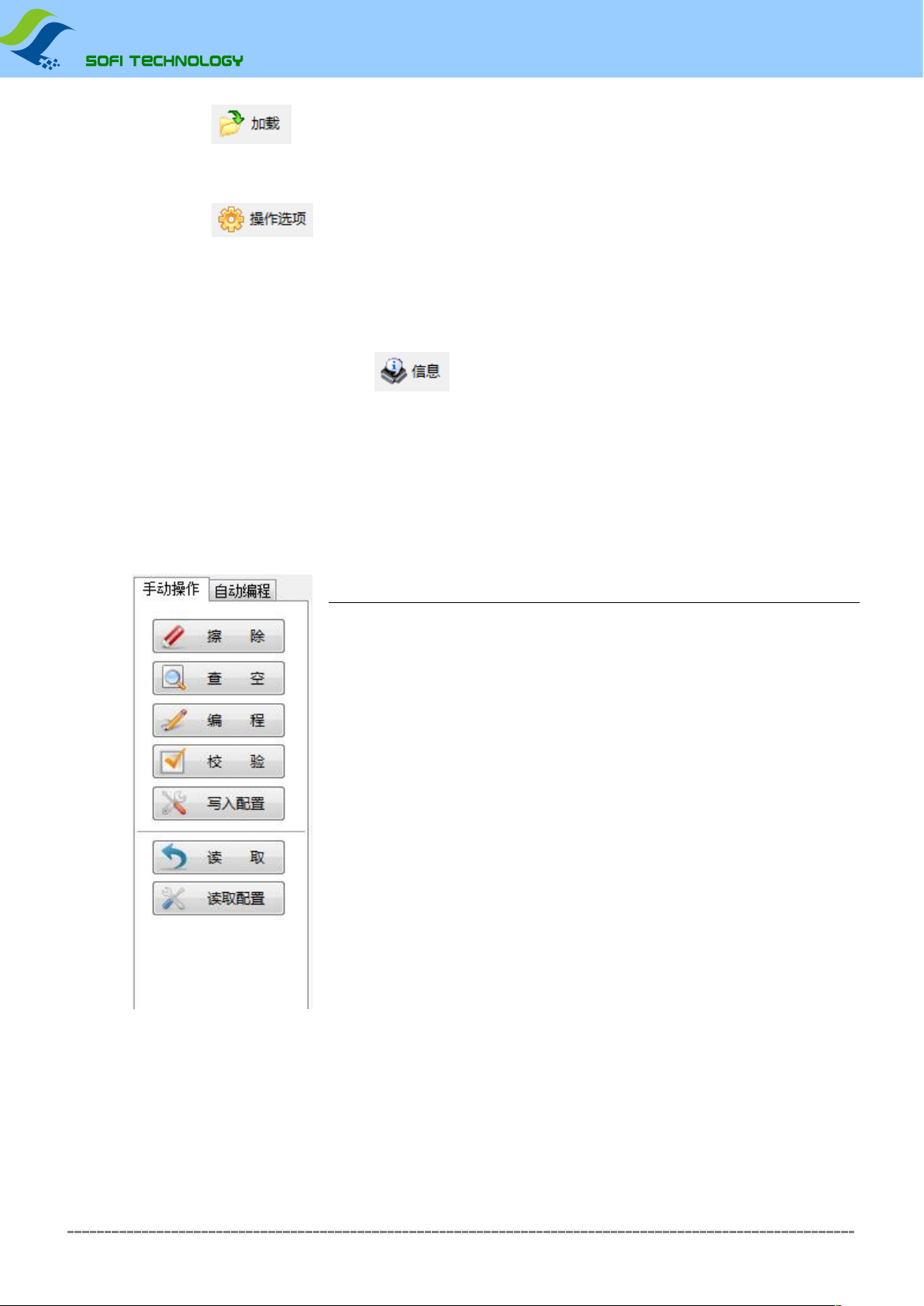
⚫manual mode
In the command bar on the left side of the main window of the software, select the "Manual Operation" page, as shown in the figure below:
button
Except: clear chip content, only forFlashclass of chips
EEPROMThe chip of this class does not have this function, this button will be disabled
(gray) Check whether the content of the chip is blank (all areFFh)
Write buffer data to the chip.
Need to preload the data file into the buffer
Compare the data in the chip with the data in the buffer (verify whether the data in the chip is
correct)
Function
wipe
check
edit
null:
Procedure:
school Test:
Write configuration:Write configuration information into the chip (egSPI FLASHof
Status Register);
Fetch: read the chip content, the read data will be saved in the software buffer, such asread
Save as a file if necessary (toolbar button: Save).
Read the configuration information of the chip, and the read configuration data will be updated to the configuration
option settings of the software. After doing this, hit the configurable option to view the current chip into the
configuration state.
Read configuration:
Typical operating steps:
➢burnSPI FLASH (25series): erase→check empty→programming→check
➢burnSPI FLASH (25series, brand new blank chip) : programming→check
➢burnI2C EEPROM (24series): programming→check
➢Read chip data and save chip data to file: read→check→save
Shenzhen Shuofei Technology Co., Ltd.8
Sofei Technology manual
SP8 series programmer
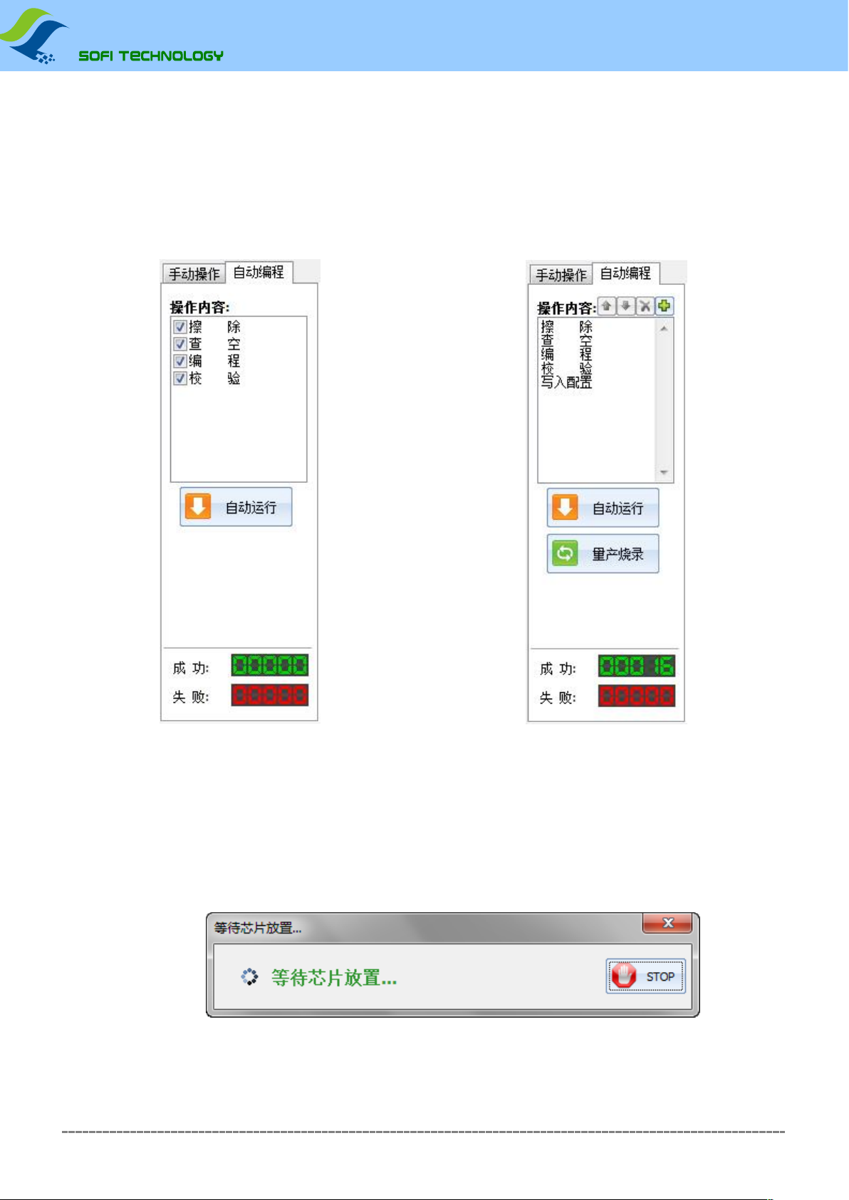
⚫automatic mode
In the command bar on the left side of the main window of the software, select the "automatic operation" page, the automatic operation page has2There are two types, namely simple setting and advanced setting,
which are determined according to different product types.
The operation sequence of the simple setting is fixed, and whether the setting operation is valid depends on whether the
check is enabled. Advanced settings can set any operation content, and the order can also be adjusted at will.
After setting the operation content, click the "Auto Run" button, and the programmer will execute the "operation content" in turn.
Easy Setup
Applicable Model:SP8-A, SP8-B
advanced settings
Applicable Model:SP8-F, SP8-FX
⚫mass production mode
The operation content of mass production mode is the same as "automatic operation", the difference is that the programmer can automatically detect the placement and removal of chips. After clicking the "Burn in mass
production" button, the software pops up a message box to remind the user to place the chip. After the chip is placed, the programming operation will be performed automatically, and the user will be reminded to
remove the chip after the programming is completed. When the user removes the chip, it will continue to wait for the placement of the next chip, and the software keeps repeating this operation until the user clicks "
STOP”button to stop operation.
Wait for the chip placement prompt
Shenzhen Shuofei Technology Co., Ltd.9

Sofei Technology manual
SP8 series programmer
Wait for the chip to be removed
illustrate
⚫Production mode is only available forSP8-B / SP8-F / SP8-FX.SP8-AThe mass production burning function is not supported.
⚫The above operations are just to demonstrate the conventional programming method of general chips, for reference only. The specific operation needs to be determined according to the user's needs.
⚫For more information about the software, please refer toFlyPROSoftware online help.
Shenzhen Shuofei Technology Co., Ltd.10
Sofei Technology manual
SP8 series programmer
Chapter 4 Offline Programming
SP8-F,SP8-FXSupport offline programming, in the offline mode, the programmer does not need to connect to the computer. Programmer built-in128MbitData storage, no additional storage device required. The
offline function has the characteristics of simple use and high burning efficiency. When the programmer works in the offline mode, it will automatically detect the chip placement, start the programming work, and
prompt the programming result through the status indicator and built-in buzzer.
Offline mode includes manual operation and automatic control.
The manual operation mode is the manual operation mode. The programmer automatically detects the placement and removal of the chip, and indicates the working state and programming result through the status indicator light and
built-in buzzer.
through automatic controlISP/ATEThe multi-function interface is connected with the automatic control machine, and the machine controls its functions and outputs corresponding indication signals to the control
machine.
SP8-FOnly supports offline manual mode;SP8-FXWith the above two modes, you can choose any one of the modes to operate through the software settings.
Download offline data
Before offline operation, the offline data must be downloaded to the programmer with a computer in advance. The data download operation steps are as follows:
1.first useUSBCable the programmer to the computer, then turn onFlyPROsoftware.
2.Select the correct chip model.
3.Load the file to be burned.
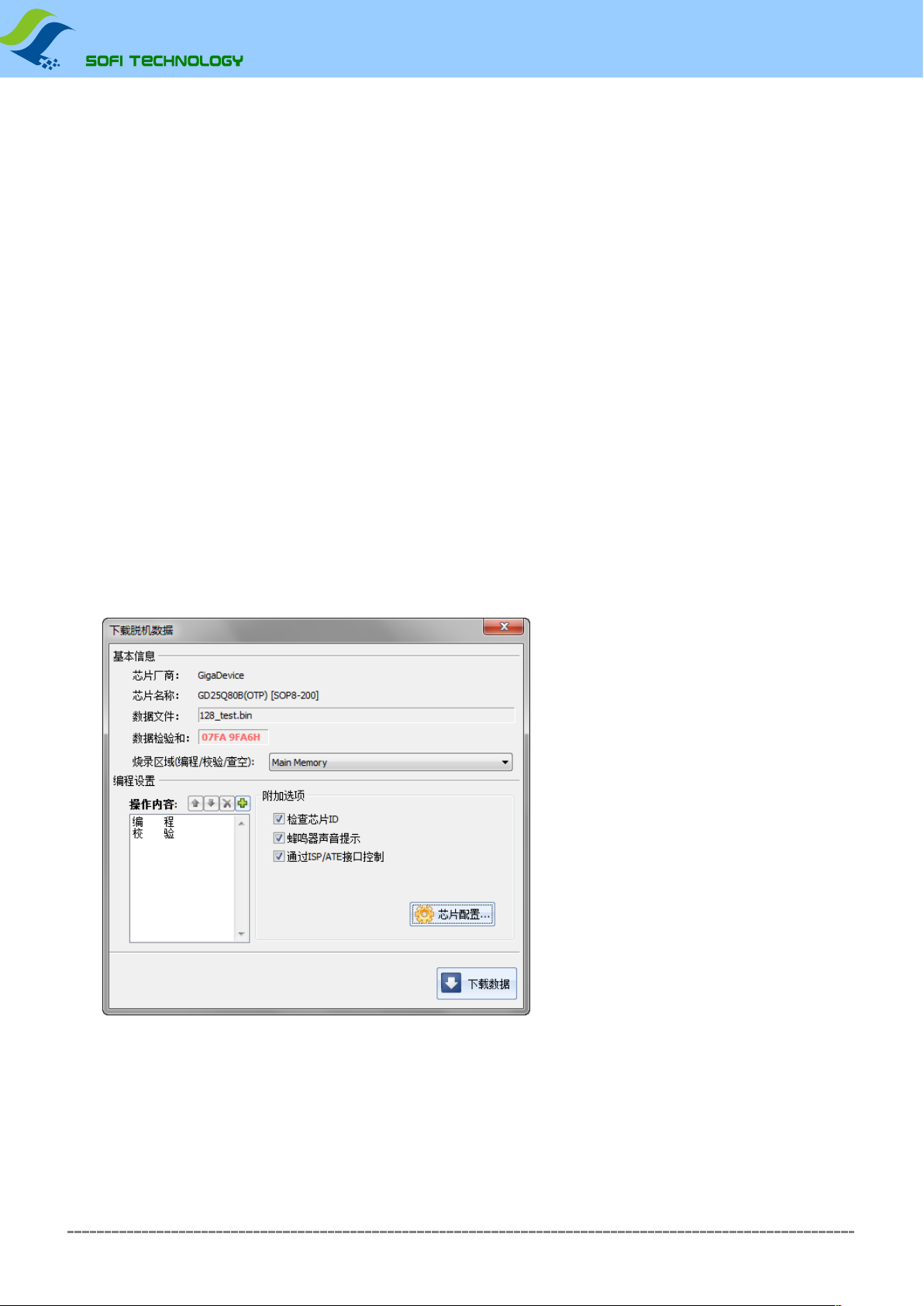
4.Click the menu [Chip] - [Offline Data Management] - [Download Offline Data] to open the offline data download dialog box and download offline data. As shown below:
passISP/ATEinterface control
This option can only beSP8-FXis available in, after checking this function,SP8-FXIt works in automatic control mode and is used to work with automatic machines. If this
function is not checked, thenSP8-FXWorks in manual operation mode.
* * *For other operation settings, please refer to the software online help or software user manual.
5.After the offline data download is complete, disconnect the connection between the computer and the programmerUSBAfter connecting the cable, the programmer can work independently from the computer.
Shenzhen Shuofei Technology Co., Ltd.11
Sofei Technology manual
SP8 series programmer
run offline‒Manual way
The offline operation steps of the programmer are as follows:
1.Power the programmer with the power adapter that came with the product.
2.After the programmer is powered on, the internal offline data will be checked first to verify the integrity and accuracy of the data.
this needs3~25seconds. If the test passes,STAThe indicator light flashes green, indicating that the programmer has entered the offline programming mode. If the detection fails,STAThe red
flashing state is displayed, indicating that there is no valid offline data in the programmer, and offline programming cannot be started.
3.Programmer'sSTAThe indicator light flashes green, indicating that it is waiting for the chip to be placed.
4.whenSTAStop flashing and display orange, indicating that the programmer has detected the chip and is programming.
5.whenSTADisplays green or red, indicating that the chip programming is complete. Green indicates that the programming is successful, and red indicates that the programming fails. At the same time the programmer starts to wait for the
current chip to be removed from the locking seat. If the buzzer prompt function is turned on, the programmer will make a sound when the programming is completed.
6.After detecting chip removal, the programmer repeats the steps3arrive5Burn the next chip.
run offline‒Automatic control method
The automatic control method is only applicable toSP8-FX, used to cooperate with automatic programming machine, manipulator and other automation equipment to realize automatic chip
operation. When downloading offline data, check the "passISP/ATEinterface control" option to turn on this function. In this way of working, the programmer'sATEinterface providedSTART start
signal, andOK / NG / BUSYindication signal.
Offline work mode status indicator
STAlight status Status Description
flashing green Waiting for chip placement (manual mode only)
orange chip is being burned
green The chip programming is completed, the programming is successful, waiting for the chip to be removed
red The chip programming failed, waiting for the chip to be removed
⚫Offline working mode, not supportedISPway to burn.
⚫When working offline, please use the power adapter provided with the product, and do not use other power sources. Incorrect use of other power sources may cause damage
to the programmer.
Shenzhen Shuofei Technology Co., Ltd.12

Sofei Technology manual
SP8 series programmer
Offline data viewing
Offline data that has been downloaded to the programmer can beFlyPROsoftware to view.
Click the menu [Chip] - [Offline Data Management] - [View Offline Data] to open the offline data viewing dialog box, as shown in the following figure:
Shenzhen Shuofei Technology Co., Ltd.13

Sofei Technology manual
SP8 series programmer
chapter FiveISPMode burning
ISPfull nameIn System Program, that is, online programming.ISPThe programming mode only needs to connect a few signal lines to the relevant pins of the on-board chip to realize the read and write operations of
the chip, which can avoid the trouble of desoldering the chip.
Use ISP programming mode
SP8The series programmer only supports some chipsISPMode burning, in the software select with "[ISP]"suffixed to the chip model number, it is indicated byISPmode to burn. (Choose notISPThe
chip model with the suffix will use the locking socket for programming,ISPThe interface has no function.) Notice:ISPDedicated for burningISPInterface connection, please do not connect the wire
from the locking seat.
ISP interface
SP8Series programmers provide an additionalISPinterface, as shown in the following figure:
9
10
7
8
5
6
3
4
1
2
ISP/ATE interface Interface Pin Diagram
ISPconnecting line
ISPThe connecting line is a ten-color colored cable, and one end of the connecting line is5x2Standard plug, access to programmerISPinterface. the other end is10Root DuPont headers and connect
to the corresponding pins on the target board.
The corresponding relationship between the color of the connecting line and the pin number is as follows
color pin number color pin number
brown 1blue 6
red 2Purple 7
orange (or pink)3grey 8
yellow 4White 9
green 5black 10
Shenzhen Shuofei Technology Co., Ltd.14
Sofei Technology manual
SP8 series programmer
target chip connection
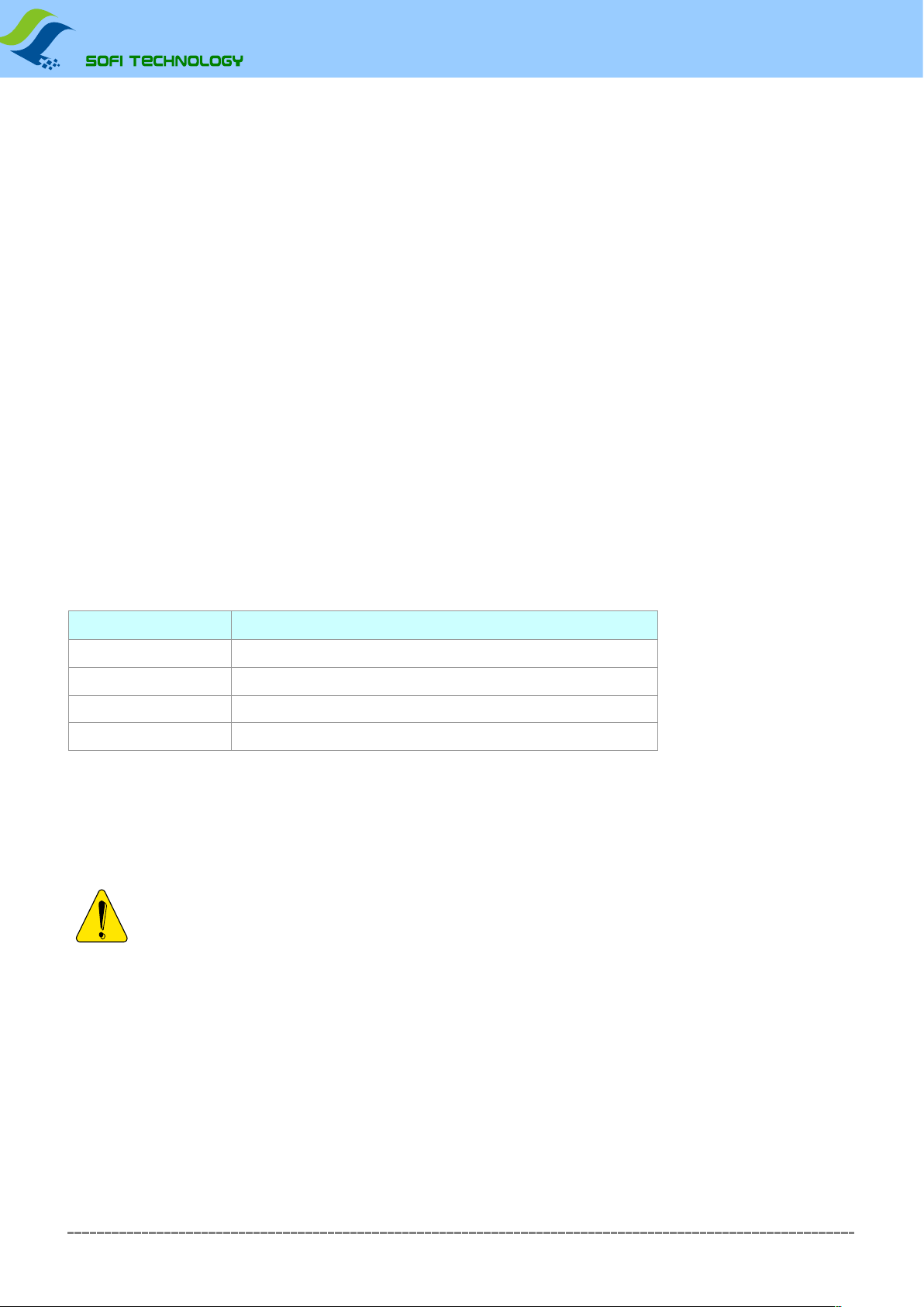
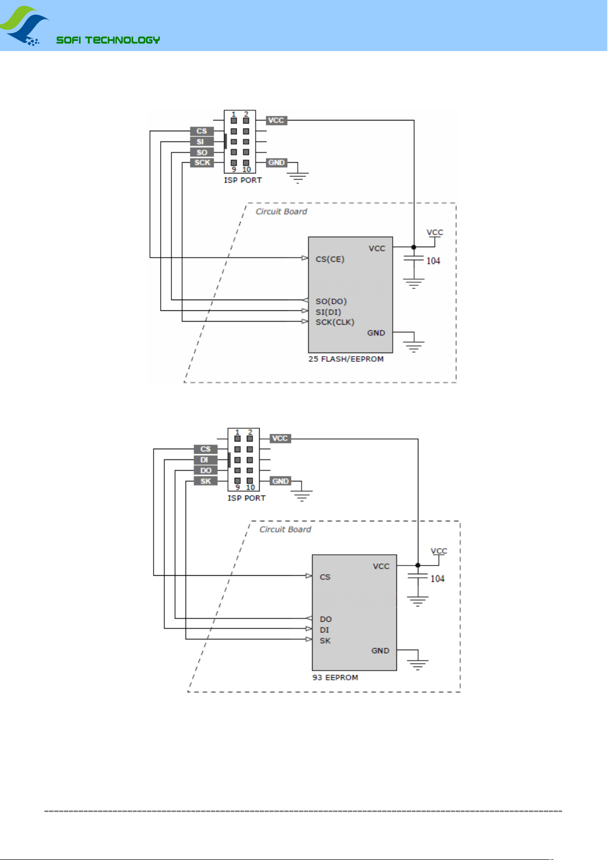
Common25series and93seriesFLASH/EEPROMThe connection diagram is as follows
typical25seriesFLASHConnection Diagram
typical93seriesEEPROMConnection Diagram
The connection method will be different for different chips. For the detailed connection information of the chip, please refer toFlyPROOpen the chip information in the software for viewing.
Shenzhen Shuofei Technology Co., Ltd.15

Sofei Technology manual
SP8 series programmer
ISPPower Mode
ISPDuring programming, the target chip has two power supply modes to choose from. power supply mode can beFlyPROset in the operating options of the software.
⚫powered by programmer
That is, the programmer provides voltage to the target board, and the power supply voltage is3.3Vor5V(existFlyPROset in the operating options of the software). In this mode, if the programmer detects that
the target board power supply already exists, it will give a power supply conflict error message. The programmer comes with an overcurrent detection function, when power is supplied to the target board,
the current is limited to250mA, when the current exceeds this range, overcurrent protection will occur. If the operating current of the target board is greater than250mA, please use the target board self-
powered mode.
⚫Target board self-powered
The programmer in this mode does not supply power to the target board.
SP8The programmer can support an operating voltage range of2.7V~5.5Vtarget board.ISPThe signal drive voltage of the target board will follow theVCCVoltage is automatically adjusted.
ISPimportant
ISPThe implementation of programming is relatively complicated, and it is suitable for people with certain professional knowledge. If only a small number of chips are to be programmed, it is recommended to remove the chips from the
board, and after programming with a conventional programming socket, solder them back to the motherboard. it might be better thanISPway more efficient. When usingISPWhen programming in this way, you must pay attention to the
following matters:
⚫Know the target board circuit diagram (if you haveISPFor consultation on programming related issues, you must provide us with the schematic diagram);
⚫useISPMode burning the chip on the board, all signal pins of the chip must be isolated from other circuits on the board, it must be ensured that the main control chip on the board does
not access the target chip, and all the connections of the main control chip must beIOIt needs to be set to a high-impedance state (the main control chip can be set toRESETstate);
⚫Regardless of the power supply mode used by the target board, the target board'sVCCmust be combined withISPthe first part of the interface2pin connection;
⚫rightISPUnused pins in the interface, please keep them floating, and do not connect with any signal in the target board;
⚫chip not connectedIOThe normal working conditions of the chip must be met (for example:25 SPI FLASHofHOLDandWPpin must be pulled high);
⚫Programmer'sISPin the interface4,6,8,10feet areGND, in practical application, usually only need to connect any one of them to the target board;
⚫Keep the line connections as short as possible (some chips even use the includedISPline, it may also be too long to cause programming failure).
pay attention:ISPBurning is from the programmerISPinterface (bottom10pindedicated interface) to connect, and select the[ISP]Model with suffix (like
The chip strip is not available in the software[ISP]Models with suffixes are available for selection, it means that the chip is not supportedISPburn),Please do not remove the40pin
socket).
Shenzhen Shuofei Technology Co., Ltd.16

Sofei Technology manual
SP8 series programmer
Appendix I Frequently Asked Questions
☺whytwenty fourSerial chip does not have erase function
◼The chip is based onEEPROMtechnology, chip data can be directly rewritten without pre-erasing, so no erase operation is available.
◼To clear the chip data, please write directly to the chipFFHdata can
☺What is the reason for the software prompting chip initialization error?
When programming some chips (such astwenty fourseries chips), the programmer will perform initialization detection on the chip, if the detection fails, it will give the error prompt. Chip
initialization errors usually have the following reasons:
◼The chip is not placed on the locking seat, or the chip pins are not in good contact
◼The chip is placed in the wrong direction or position
◼There is a problem with the chip itself
◼The chip model does not match, that is, the model selected in the software is different from the one actually placed on the locking seat
◼ISPConnection line problem (onlyISPmode, i.e. with [ISP]suffix chip)
☺What is the reason for the programmed chip not working properly?
The programmed chip does not work normally for the following reasons:
◼The data file is not loaded correctly before flashing the chip
◼There is a problem with the data file itself
◼Programming operation step error
◼Chip working circuit/voltage problem
☺Is it possible to program the chips on other circuit boards with the leads on the locking seat?
Can't. It is forbidden to use this method to program the chip, as this method may cause permanent damage to the programmer. The resulting damage to the programmer will not be
covered by the free warranty.
☺Can the burner burn?imgdocument?
The file encoding formats supported by the burner software are binary (binary) and hexadecimal (Inter HEX) formats, the regular suffix of binary files is *.bin,
and the regular suffix of hexadecimal files is *.hex
img is just a file suffix and does not represent the file encoding format. Usually (more than 90%) such files are binary encoding, and can be loaded directly in the software.
The software will automatically identify whether the file is binary encoding and use the recognized format. to load.
In order to ensure the accuracy of file loading, we recommend that users check the buffer checksum and file checksum (in the programmer software) with engineering technicians (or file
code providers/customers, etc.) after loading such files. This information will be displayed at the bottom of the main window).
☺How should the chip configuration bits be set?
All configuration options of the chip are listed according to the specifications of the chip manufacturer, and the user needs to make the correct configuration according to their own project
needs and chip specifications.The programmer is only responsible for writing the data set by the user into the chip, the programmer manufacturer cannot tell the user how to set it, please
contact the project engineer/code provider.
The configuration option is realized by "Write Configuration". In automatic programming (including offline operation/machine operation), the write configuration needs to be added to the last step of the
operation, for example: "Program"→”check"→”write configuration"
Shenzhen Shuofei Technology Co., Ltd.17

Sofei Technology manual
SP8 series programmer
☺The programmed chip is soldered to the upper part of the product and cannot run, but it can be re-programmed after soldering it down. Is it because the programmer did not program the chip correctly?
During the final test of the product, it is found that the data in some chips is wrong/or lost/or empty chips. There are many reasons for this. The following
common situations are:
1. When the product is powered on and tested, due to interference, unstable power supply, abnormal access, software malfunction, etc., the chip data will be rewritten or erased.
2. When sorting chips, mix up <put the chip that failed to be programmed, or the chip that has not been programmed to the OK side>
3. The temperature stability of the chip is poor, and data is lost or changed due to high temperature during soldering. According to our statistics, most of the problems are in cases 1 and 2,
and no cases caused by the programmer have been found for the time being. Ensure that the chip data after programming is correct. For the data errors found after high temperature
soldering, the product is powered on and running <chip has been read/written> and other processes, it is not within the scope of the programmer's guarantee.
If you want to rule out or verify if there is a problem with the programmer, it is recommended to do a 100% inspection of the chip before SMD soldering.
For case 1: If the chip is SPI FLASH, there is a way to avoid it, that is, when programming the chip, add a protection function to the chip to
prevent accidental overwriting, see:http://www.sofi-tech.com/html/6184791048.html
☺ISPWhat are the precautions for burning?
The implementation of ISP programming is relatively complicated, and it is suitable for people with certain professional knowledge. If only a small number of chips are to be programmed, it is recommended to remove the chips
from the board, and after programming with a conventional programming socket, solder them back to the motherboard. . This may be more efficient than the ISP method. When using the ISP method to program, you must pay
attention to the following matters:
1. Know the circuit diagram of the target board. <If you have questions about ISP programming, you must provide us with the schematic diagram>
2. When the programmer is programming the target chip, it must be ensured that the main control chip on the board does not access the target chip, and all the connected IOs of the main
control chip must be set to a high-impedance state. <You can try to set the main control chip to for RESET status>
3. Keep the line connection as short as possible. <Some chips may be too long even with the included ISP line>
4. The IOs that are not connected to the chip must meet the normal working conditions of the chip.
For example: HOLD and WP pins of 25 SPI FLASH must be pulled up to high level.
Special attention: ISP programming is to connect from the ISP interface of the programmer (the dedicated interface of the bottom 10pin), and select the model with the [ISP] suffix in the
software (if there is no [ISP] suffix after the chip model, it means no This chip supports ISP programming), please do not connect the cable from the locking socket (40pin socket).
Shenzhen Shuofei Technology Co., Ltd.18

Sofei Technology manual
SP8 series programmer
Appendix II Disclaimer
Shenzhen Shuofei Technology Co., Ltd. will do its best to ensure the correctness of the product and its related software and data. For possible product (including software and
related data) defects and errors, the company will try its best to solve the problem with commercial and technical capabilities. The company is not responsible for all kinds of
incidental, consequential, direct, indirect, special, extended or punitive damages arising from the use or sale of this product, including but not limited to profits, goodwill, loss of
availability, Business interruption, data loss, etc., do not bear any direct, indirect, incidental, special, derivative, punitive damages and third-party claims.
Shenzhen Shuofei Technology Co., Ltd.19

Sofei Technology manual
SP8 series programmer
Appendix IV Document Revision Record
release date Version Revised by illustrate
2011-08 A2 Freeman the first1Version
2011-12 A3 Freeman Modify file load/save content
Increase25seriesSPI FLASHModel detection function update
software /USBDriver installation content
2013-04 A4 Freeman corresponds toV2.61and aboveFlyPROThe software increases the data buffer search
function, modifies the logic operation, and adds the byte exchange content to the chip
IDError handling
add disclaimer
2014-11 B1 Freeman Cancel the software description part, please refer to the independent software user manual for the software part.
2016-08 B2 Freeman Update product selection table
2018-05 B3 Sauwa IncreaseFAQ
2018-07 B4 Freeman Update some software pictures
Shenzhen Shuofei Technology Co., Ltd.20
Other manuals for SP8 Series
1
This manual suits for next models
4
Table of contents
Other Sofi Motherboard manuals


