SOFT ROBOTICS mGrip User manual

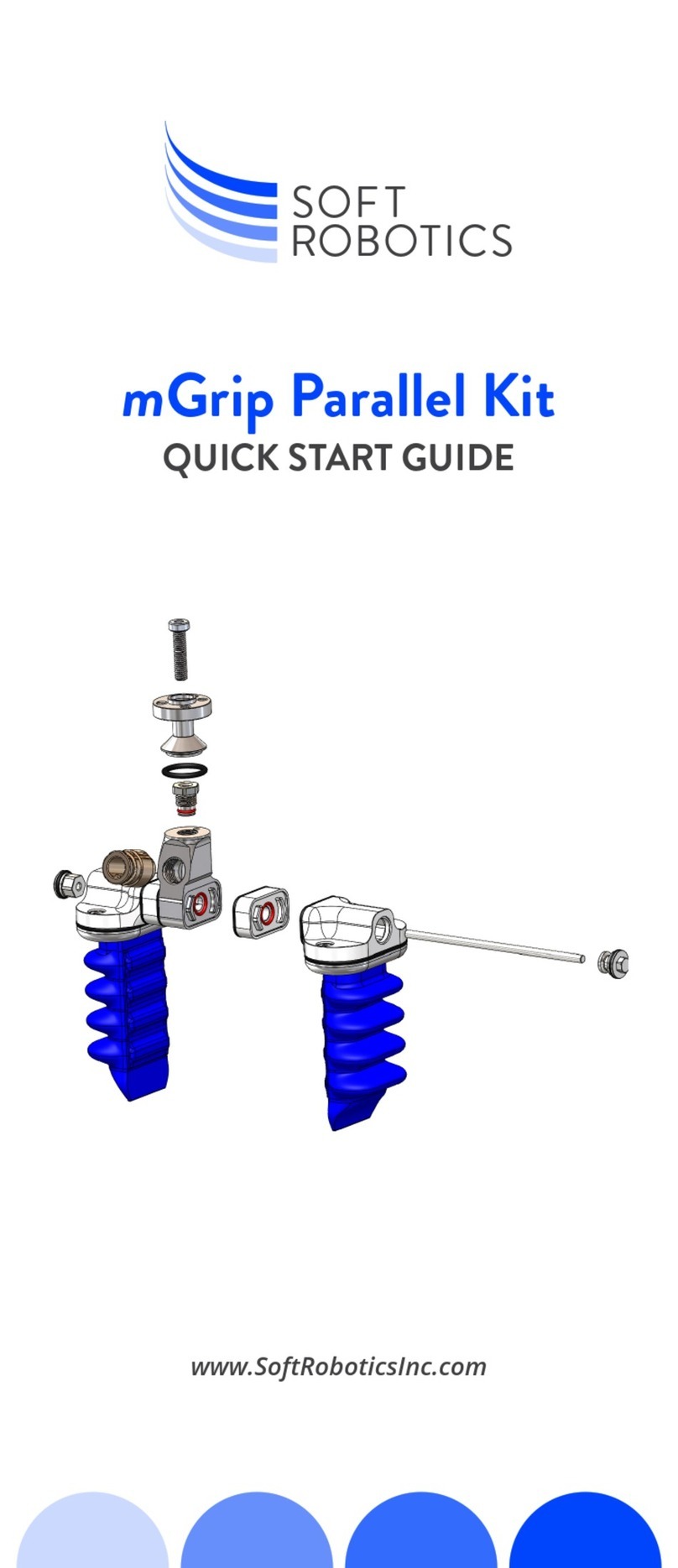
mGrip™
Parallel Gripper
QUICK START GUIDE
For 2, 4, and 6 nger
parallel congurations

P/N 800130 Rev B
For more information, visit:
softroboticsinc.com/mgrip
Revolutionary
Technology
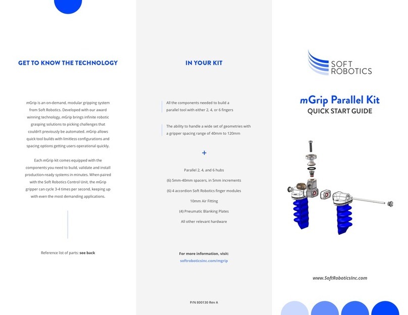
The Soft Robotics mGrip modular gripping
system is a suite of congurable gripper and
controller products that enables reliable,
high-speed picking of traditionally hard
to grasp items in the food and beverage
processing and consumer packaged goods
industries.

PARALLEL KIT SPACER AND TIE ROD CHART
Grip Spacing (mm)
40
50
60
70
80
90
100
110
120
Blanking Plate
0
5
10
15
20
25
30
35
40
-
85
95
105
115
125
135
145
155
165
35
Spacer (mm) Tie Rod (mm)
7
Use the M4 Hex Nut to be tightened
onto Tie Rod (after Anti-Seize applied)
and then used to attached Finger
Module and Spacer (if required) to hub.
Note: Use the tie rod and spacer chart (located on the right panel of this guide) to identify
which tie rod is best for your gripper.We recommend using food-safe anti-seize lubricant when
torquing tie-rods. We recommend Anti-Seize gel onto Tie Rod before M4 Hex Nut is installed.
Note: Fingers can be mounted
directly to the hub if spacers are
not being used. Note: We recommend Anti-Seize gel onto
Tie Rod before M4 Cap Nut installation.
11
Repeat steps 5 through 10 to
secure other Spacers and Finger
Modules to the Parallel Hub
(for Parallel 4 and Parallel 6 EOATs)
8
Install the second Spacer, if
required, onto the opposite side
of the Parallel Hub by passing
the tie rod through the center of
the spacer and pressing rmly
against the Parallel Hub.
Install the desired Spacer
onto the Parallel Hub (if
required) by aligning the
features and pressing rmly.
Install the second Finger
Module onto Spacer and
through the tie rod.
5 9
6
Install Finger Module onto
the Spacer by aligning
features and pressing rmly.
10
Install an M4 Sealing Cap
Nut onto the end of the tie
rod to secure the Spacers
and Finger Modules in place.
Torque Hex Nut to 2.2Nm.
Install the Air Fitting
onto the desired Parallel
Hub. Torque to 6Nm.
Install the Robot Adapter
onto the Parallel Hub.
Insert the M6 Screw to attach
Robot Adapter through
Parallel Hub. Torque this
screw to 7.4Nm.
Note: We recommend Anti-Seize
gel onto M6 screw before
installation.
Ensure O-Rings are
installed on the Parallel
Hub and did not come
loose during shipping.
1
2
3
4

PARALLEL KIT SPACER AND TIE ROD CHART
Grip Spacing (mm)
40
50
60
70
80
90
100
110
120
Blanking Plate
0
5
10
15
20
25
30
35
40
-
85
95
105
115
125
135
145
155
165
35
Spacer (mm) Tie Rod (mm)
3
Insert the M6 Screw to attach
Robot Adapter through Parallel
Hub. Torque this screw to 5Nm.
Note: We recommend Anti-Seize gel
onto M6 screw before installation.
Note: We recommend Anti-Seize gel onto
Tie Rod before M4 Cap Nut installation.
11
Repeat steps 5 through 10 to
secure other Spacers and Finger
Modules to the Parallel Hub
(for Parallel 4 and Parallel 6 EOATs)
4
Ensure O-Rings are installed
on the Parallel Hub and did not
come loose during shipping.
Install the Air Fitting onto
the desired Parallel Hub.
Torque to 6Nm.
Install the second Finger
Module onto Spacer and
through the tie rod.
1 9
2
Install the Robot Adapter
onto the Parallel Hub.
10
Install an M4 Sealing Cap
Nut onto the end of the tie
rod to secure the Spacers
and Finger Modules in place.
Torque Hex Nut to 2.2Nm.
Note: Fingers can be mounted
directly to the hub if spacers
are not being used.
Install the second Spacer, if
required, onto the opposite
side of the Parallel Hub by
passing the tie rod through
the center of the spacer and
pressing rmly against the
Parallel Hub.
Install the desired Spacer
onto the Parallel Hub (if
required) by aligning the
features and pressing
rmly.
Install Finger Module
onto the Spacer by
aligning features and
pressing rmly.
5
6
7
8
Tighten the Hex Nut onto the tie
rod (after anti-seize is applied) and
then place through the installed
nger module and spacer (if
present) to attach to the hub.
Note: Use the Tie Rod and spacer chart (located on the right panel
of this guide) to identify which tie rod is best for your gripper.
We recommend Anti-Seize gel onto the Tie Rod before M4 Hex
Nut is installed.

3
7
Insert the M6 Screw to attach
Robot Adapter through Parallel
Hub. Torque this screw to 5Nm.
Use the M4 Hex Nut to be tightened
onto Tie Rod (after Anti-Seize applied)
and then used to attached Finger
Module and Spacer (if required) to hub.
Note: Use the tie rod and spacer chart (located on the right panel of this guide) to identify
which tie rod is best for your gripper.We recommend using food-safe anti-seize lubricant when
torquing tie-rods. We recommend Anti-Seize gel onto Tie Rod before M4 Hex Nut is installed.
Note: We recommend Anti-Seize gel
onto M6 screw before installation.
Note: Fingers can be mounted
directly to the hub if spacers are
not being used.
4
8
Ensure O-Rings are installed
on the Parallel Hub and did not
come loose during shipping.
Install the second Spacer, if
required, onto the opposite side
of the Parallel Hub by passing
the tie rod through the center of
the spacer and pressing rmly
against the Parallel Hub.
Install the Air Fitting onto
the desired Parallel Hub.
Torque to 6Nm.
Install the desired Spacer
onto the Parallel Hub (if
required) by aligning the
features and pressing rmly.
1 5
2
Install the Robot Adapter
onto the Parallel Hub.
6
Install Finger Module onto
the Spacer by aligning
features and pressing rmly.
Note: We recommend Anti-Seize gel onto
Tie Rod before M4 Cap Nut installation.
Install the second Finger
Module onto Spacer and
through the tie rod.
Install an M4 Sealing Cap
Nut onto the end of the tie
rod to secure the Spacers
and Finger Modules in
place. Torque Hex Nut to
2.2Nm.
9
10
11
Repeat steps 5 through
10 to secure other Spacers
and Finger Modules to the
Parallel Hub (for Parallel 4
and Parallel 6 EOATs)
Note: After the EOAT has been
present in its operating envi-
ronment for at least 8 hours,
Torque the center hub bolt to
7.4Nm for optimal operation.

Parallel EOAT
Traditional Finger Modules Compact Finger Modules
Grip Spacing Spacer Size Tie Rod Size Spacer Size Tie Rod Size
N/A Blanking Plate 35 Blanking Plate 35
20 - - None 75
30 - - 5 85
40 None 85 10 95
50 5 95 15 105
60 10 105 20 115
70 15 115 25 125
80 20 125 30 135
90 25 135 35 145
100 30 145 40 155
110 35 155 - -
120 40 165 - -
Other SOFT ROBOTICS Robotics manuals
