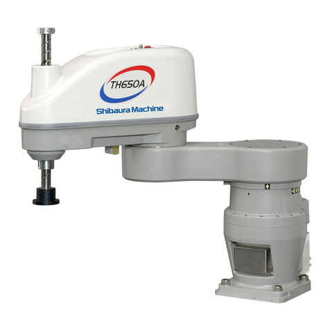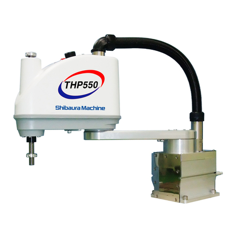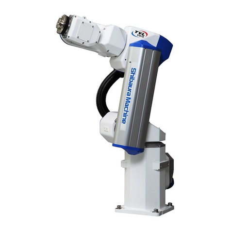
TRANSPORTATION AND INSTALLATION MANUAL
Table of Contents
Page
Section 1 Transportation...................................................................................................9
1.1 Unpacking.........................................................................................................9
1.2 Transportation ................................................................................................12
1.2.1 Mass and Dimensions.....................................................................................12
1.2.2 Transporting the Robot...................................................................................12
1.2.3 Transporting the Controller.............................................................................16
1.3 Storage...........................................................................................................16
1.3.1 Storage Precautions for the Robot..................................................................16
1.3.2 Storage Precautions for the Controller............................................................16
Section 2 Installation.......................................................................................................17
2.1 Installation Environment .................................................................................17
2.2 Robot Installation............................................................................................18
2.2.1 External Dimensions.......................................................................................18
2.2.2 Working Envelope...........................................................................................18
2.2.3 Coordinate System .........................................................................................22
2.2.4 Installing the Robot.........................................................................................26
2.3 Changing the Mechanical Ends......................................................................29
2.3.1 Changing the Mechanical Ends of Axes 1 and 2 (TH180)..............................30
2.3.2 Changing the Mechanical Ends of Axis 3........................................................37
2.3.3 Changing Software Limits...............................................................................44
2.4 Installing the Controller..........................................................................................45
2.4.1 External Dimensions.......................................................................................45
2.4.2 Precautions for Direct Installation ...................................................................46
2.4.3 Rack Mounting Dimensions ............................................................................47
2.4.4 Precautions for Rack Mounting.......................................................................48
2.5Precautions for Handling the Teach Pendant.................................................50
2.6 Safety Measures.............................................................................................51
2.7 Position Detector Backup Batteries................................................................52
2.8 Using the Robot in Clean Room .....................................................................53
Section 3 System Connections.......................................................................................54
3.1 Cable Wiring...................................................................................................54
3.1.1 Connector Arrangement on the Controller......................................................54
3.1.2 Connecting the Power Cable “ACIN” [1] of Fig. 3.1 (Plug Connector Attached)
........................................................................................................................55
3.1.3 Connecting the Motor Cable “MOTOR” Fig. 3.1-[1] (Cable Attached).............56
3.1.4 Connecting the Encoder Cable “ENC” Fig. 3.1 [3] (Cable attached)...............58
3.1.5 Connecting the Hand Control Signal Cable “HAND” Fig. 3.1-[4] (Cable
Optional).........................................................................................................58
3.1.6 Connecting the Brake Signal Cable "BRK" Fig. 3.1-[8] (Cable Attached).......58
3.1.7 Grounding the Robot.......................................................................................59
3.1.8 Inserting and Removing Cables......................................................................59
3.1.9 Examples of Connector Terminal Arrangement..............................................61
3.2 Controller Connector Signals..........................................................................63
3.2.1 Connector Signal Connection Diagrams.........................................................63
3.3 Separating Control Panel from Controller.......................................................64
STE 85389
– 7 –
