Version EN-082020-1.00 3
Table of Contents
Table of Contents
Chapter 1 ...................................................................................... 5
About this guide
............................................................................................................... 51.1 Read me first
............................................................................................................... 51.2 Target audience
............................................................................................................... 51.3 Typographic conventions
............................................................................................................... 61.4 Document history
............................................................................................................... 61.5 Related documentation and videos
............................................................................................................... 61.6 Document feedback
Chapter 2 ...................................................................................... 7
About smartLink HW-DP
............................................................................................................... 72.1 Intended use
............................................................................................................... 72.2 Specifications
............................................................................................................... 72.3 Supported features
............................................................................................................... 82.4 System requirements
............................................................................................................... 82.5 Safety precautions
Chapter 3 ...................................................................................... 9
Installation
............................................................................................................... 93.1 Hardware installation
.......................................................................................................... 9
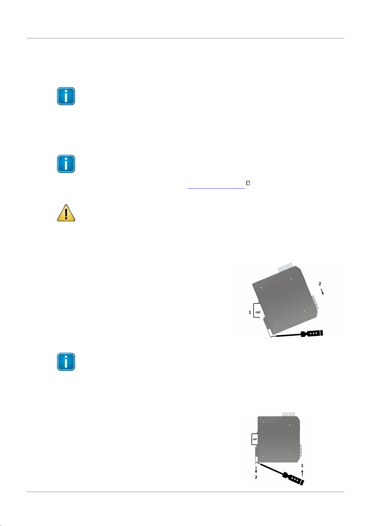
Mounting and dismounting
3.1.1
.......................................................................................................... 10
Connection diagrams
3.1.2
.......................................................................................................... 11
Power and alarm connectors
3.1.3
.......................................................................................................... 12
Installation positions
3.1.4
.......................................................................................................... 13
Connecting to the network
3.1.5
.......................................................................................................... 13
Powering up the device
3.1.6
.......................................................................................................... 14
Factory reset
3.1.7
............................................................................................................... 153.2 Software installation
Chapter 4 ...................................................................................... 16
Configuration
............................................................................................................... 164.1 Prerequisites
............................................................................................................... 164.2 Changing the IP address of a smartLink HW-DP
............................................................................................................... 184.3 Setting the IP address of your PC
............................................................................................................... 194.4 Login to user interface
............................................................................................................... 194.5 Configuring PROFIBUS
Chapter 5 ...................................................................................... 20
Connecting with Emerson AMS
............................................................................................................... 205.1 Preparations
............................................................................................................... 205.2 Network configuration
Chapter 6 ...................................................................................... 24
LED status indicators
............................................................................................................... 256.1 Status LEDs startup phase
............................................................................................................... 256.2 Status LEDs – factory mode
............................................................................................................... 256.3 Status LEDs – normal mode