TESTERON Tracker Pro V3 User manual
I N S T R U C T I O N M A N U A L
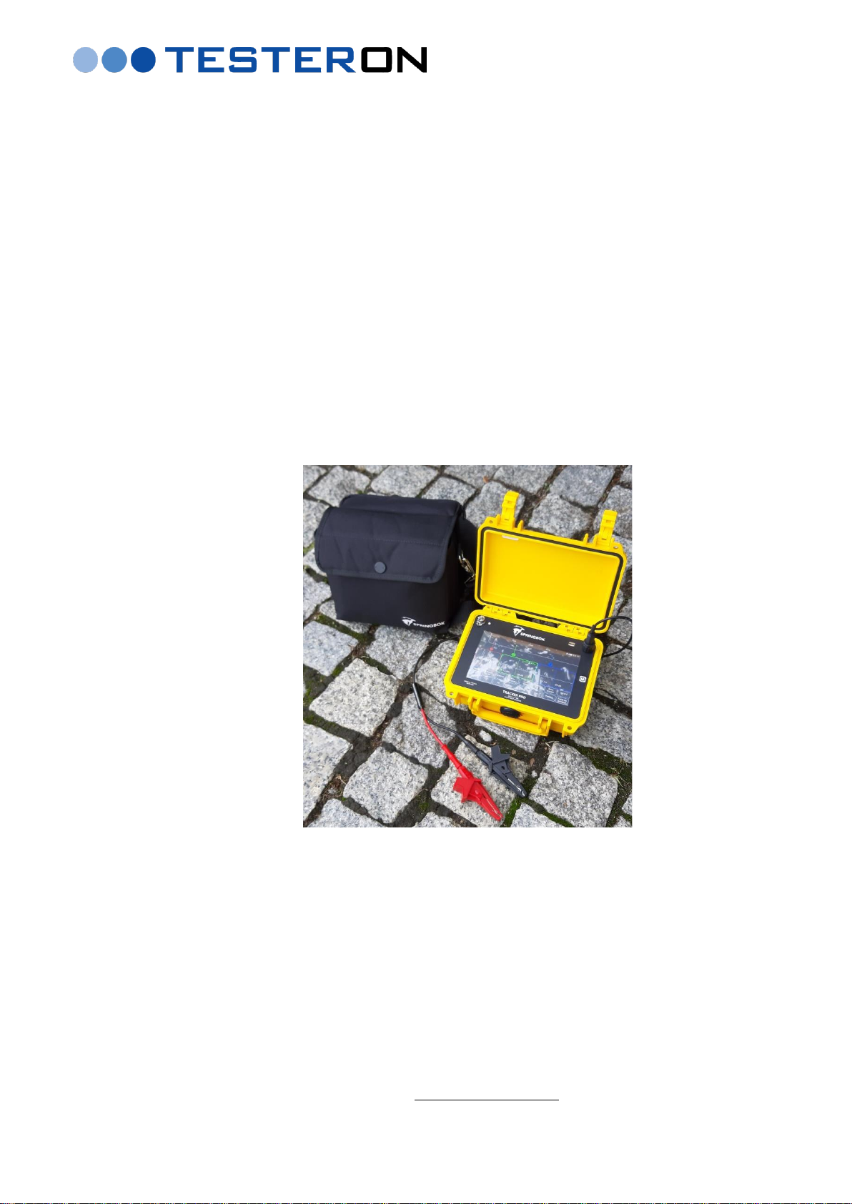
Tracker Pro
(Model V3)
Time Domain Reflectometer (TDR)
for metal cable faultfinding and troubleshooting
as well as
for district heating pipelines troubleshooting and monitoring
D I S T R I B U T O R I N T H E E U:
TESTERON
ul. Nowy Rynek 6
62-002 Suchy Las, Poland
tel +48 61 6521235
cell phone. +48 724 565157
e-mail: biuro@testeron.pl
rev. 11-2020-ENG

Tracker Pro TDR Instruction Manual
Page 2of 44
Table of Contents
1. General Information .......................................................................................................................................4
1.1 Introduction ................................................................................................................................................................. 4
1.2 Tracker Pro’s Key-Features........................................................................................................................................ 4
1.3 Tracker Pro’s Typical Field Applications................................................................................................................. 4
1.4 Theory of Operation.................................................................................................................................................... 5
1.5 Safety Information....................................................................................................................................................... 5
2. Description .......................................................................................................................................................6
2.1 Front Panel ................................................................................................................................................................... 6
2.2 Touch Screen................................................................................................................................................................ 6
2.3 Intuitive Ease of Use ................................................................................................................................................... 7
2.4 Touch & Jump.............................................................................................................................................................. 7
2.5 Return Loss .................................................................................................................................................................. 8
2.6 Pulse.............................................................................................................................................................................. 9
2.7 Vertical Gain ................................................................................................................................................................ 9
2.8 Range .......................................................................................................................................................................... 10
2.9 Horizontal Position ................................................................................................................................................... 10
2.10 VOP (Velocity of Propagation).............................................................................................................................. 10
2.10.1 Determine VOP................................................................................................................................................ 10
2.10.2 Reducing VOP Error ....................................................................................................................................... 10
2.10.3 Set up VOP for the Actual Cable Test........................................................................................................... 10
2.11 Filters......................................................................................................................................................................... 11
2.12 Auto-Search.............................................................................................................................................................. 12
2.13 Menu ......................................................................................................................................................................... 12
2.13.1 Internal Software Revision ............................................................................................................................. 12
2.13.2 Event Markers.................................................................................................................................................. 12
2.13.3 Settings.............................................................................................................................................................. 13
2.13.4 Adjusting the Time and Date......................................................................................................................... 14
2.13.5 Flip Screen ........................................................................................................................................................ 14
2.13.7 IFD Mode (Intermittent Fault Detection) ..................................................................................................... 15
2.14 Internal Memory...................................................................................................................................................... 17
2.14.1 Storing of Waveforms ..................................................................................................................................... 17
2.14.2 Saved Waveforms............................................................................................................................................ 17
2.14.3 Procedure of Viewing Saved Waveforms .................................................................................................... 17
2.14.4 Editing Comments........................................................................................................................................... 18
2.14.5 Deleting of Waveforms from the TDR.......................................................................................................... 18
2.14.6 Downloading of Saved Waveforms into a PC ............................................................................................. 19
2.14.7 Downloading of Saved Waveforms into a Mobile Device ......................................................................... 20
3. Charging the Batteries ..................................................................................................................................20
4. Examples of Waveforms...............................................................................................................................21
5. TrackerView PC Application to Tracker series TDRs............................................................................24
5.1 Availability of TrackerView application................................................................................................................ 24
5.2 The screen layout....................................................................................................................................................... 24
5.2.1 Upper Tool Bar................................................................................................................................................... 25
5.2.2 Comparing waveforms - OVERLAY .............................................................................................................. 26
5.2.3 „Mirror Horizontal” Feature............................................................................................................................ 27
5.2.4 Info + Communication Control Bar ................................................................................................................ 28
5.2.5 Download File from Instrument...................................................................................................................... 28
5.2.6 Update Instrument Firmware.......................................................................................................................... 29
5.2.7 Distance Scale..................................................................................................................................................... 29
5.2.8 Waveform and Cursors..................................................................................................................................... 29
5.2.9 Main Control Panel ........................................................................................................................................... 30
5.2.10 Full testing screen option ............................................................................................................................... 33
5.2.11 Comment Box................................................................................................................................................... 34

Tracker Pro TDR Instruction Manual
Page 3of 44
6. TrackerView Apps for tablets and smartphones.....................................................................................35
6.1 Upper Tool Bar .......................................................................................................................................................... 35
6.2 Info Screen.................................................................................................................................................................. 36
6.3 Distance Scale ............................................................................................................................................................ 36
6.4 Waveform and Cursors ............................................................................................................................................ 37
6.5 Control Panel ............................................................................................................................................................. 37
6.6 Downloading of test data from the Tracker series TDR into a mobile device .................................................. 40
7. Maintenance ...................................................................................................................................................42
7.1 Cleaning...................................................................................................................................................................... 42
7.2 Periodic Inspection.................................................................................................................................................... 42
7.3 Instrument Disposal.................................................................................................................................................. 42
8. Service and Warranty....................................................................................................................................42
9. Technical Data................................................................................................................................................43
9.1 Technical Specification ............................................................................................................................................. 43
9.2 VOP Value Table for Different Types of Networks to be tested with the TDR ................................................ 44
Tracker Pro TDR Instruction Manual
Page 4of 44
1. General Information
1.1 Introduction
The Tracker Pro is a multipurpose metallic time domain reflectometer (TDR). It is a cable fault locator designed
to quickly and easily diagnose metallic cables. The Tracker Pro combines the latest technology and user-friendly
operation, creating a versatile and accurate TDR. It uses square pulse widths with very fast rising and falling
edges. This unique capability creates high frequencies that allow for the most accurate reading of small faults in
the cable even at very short distances less than 1m from the source of the test pulse. At the same time, a
combination of available testing pulse widths allows the user to test cable networks and district heating pipelines
on long distances up to 16km on coax cables or 19km on alarm systems of pipelines.
The Tracker Pro is a product of Springbok Instruments, USA, whose founders created RiserBond over two
decades ago - a world known brand of metallic TDRs. As compared to all existing TDRs, Springbok Instruments
introduces some revolutionary new features as standard: a high resolution color touch LCD screen and the
Tracker Store –a unique system of storing measurement data, each file being a full waveform with all the available
pulse widths regardless of what is on screen.
1.2 Tracker Pro’s Key-Features
•the most modern TDR technology based on high frequency energy test pulses
•locates faults (cable impedance discontinuities) for most of metallic cable types
•long testing range up to 16km on coax cables or 19km on district heating pipelines
•detects faults at very short distances –less than 1m with a 5ns pulse width
•high resolution large color touch LCD screen
•Auto-Search mode for ease of operation
•three measurement cursors and multiple marking system
•intuitive interface combined with accurate diagnose & locating of multiple events on a cable
•unique „one-touch storage of all pulse width” Tracker Store System for 60 cable tests
•IFD mode (Intermittent Fault Detection)
•Bluetooth 4 and USB connectivity to tablets and smartphones
•splash proof USB connection and Tracker View PC software at standard delivery
•updates of the Tracker Pro’s operating system & Tracker View PC software via internet for free
•increased operating time of the internal battery exceeding 9 hours in standard conditions
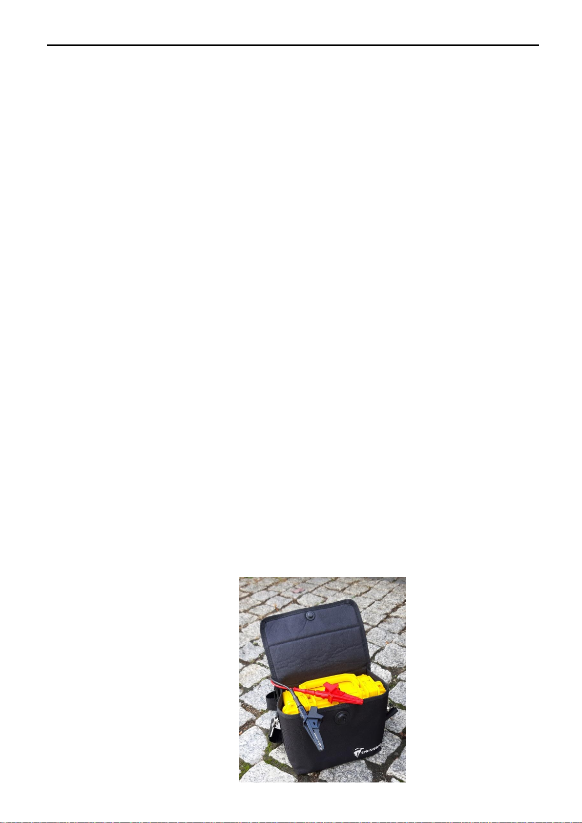
•rugged and field tested case
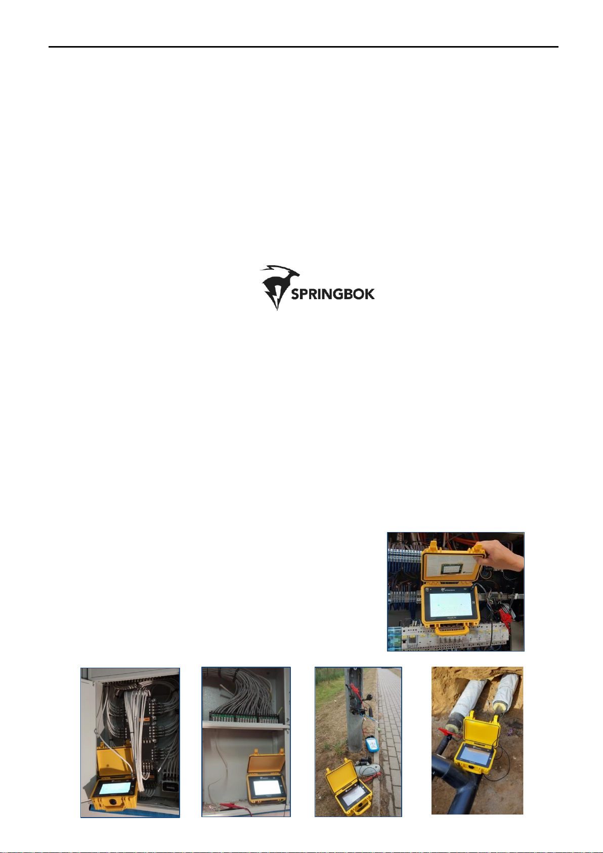
1.3 Tracker Pro’s Typical Field Applications
Typical field applications for Tracker Pro TDR include:
➢coax cable TV troubleshooting
➢telecom copper cable faultfinding
➢railway automation cables troubleshooting
➢LV power cable faultfinding
➢district heating network troubleshooting
➢and many more….
Tracker Pro TDR Instruction Manual
Page 5of 44
1.4 Theory of Operation
Tracker Pro was successfully introduced to the world market over 5 years ago. It is a reflectometer designed to
detect and analyze faults on metal cables. It belongs to the group of measurement devices called TDR (Time
Domain Reflectometer). Using time domain reflectometry, or cable radar, the TDR transmits a signal down the
cable. Impedance discontinues along the length of the cable reflect some or all of the signal energy back to the
instrument. These reflections are measured and displayed on the Tracker Pro’s color LCD touch screen as both a
waveform and a numeric distance to the fault.
If the pulse reaches an impedance discontinuity, part or all of the pulse energy is reflected back to the instrument.
If the cable is an open circuit, the reflected pulse will be in-phase (upward reflection) with the output pulse. If the
cable is a short circuit, the reflected pulse will be out-of- phase (downward reflection) with the output pulse. In
either case, a substantial amount of energy will be reflected. If it were possible to have a cable with no loss, all of
the signal energy would be reflected. The incident and the reflected signals would look identical. Inductive faults
and reflections from an impedance higher than the characteristic impedance will be in-phase, or upward.
Capacitive faults and reflections from a lower impedance are out-of-phase, or downward.
The Tracker Pro displays the cable under test as a digitized waveform with a numeric distance readout on the
touchscreen display. The digitized waveform enables the operator to view the signature of the cable in great
detail. An impedance mismatch (opens, shorts or faults of less severity) can be identified and distances to the
faults determined. The Tracker Pro will test all types of metallic paired cables for opens, shorts and impedance
mismatch.
Square Pulses
The Tracker Pro uses square pulse widths with very fast rising and falling edges. This unique capability creates
high frequencies that allow for the most accurate reading of small faults in the cable. Due to high frequency energy
of the pulses, the minimum effective test range of the first 2nsec pulse is less than 0,5m! The combination of
available testing pulse widths for the instrument allows the user to test cable networks and district heating
pipelines on long distances up to 16km on coax cables or 19km on alarm systems of pipelines.
1.5 Safety Information
WARNINGS:
•Review all safety precautions before using.
•Do not operate this instrument near flammable gases or fumes!
•Do not modify any part or accessory of this instrument.
•If the unit is damaged, do not use.
•To avoid electric shock, do not remove covers or any parts of the enclosure!
CAUTION:
As with most electronic equipment, care should be taken not to expose the equipment to extreme temperatures
or humidity. Store the instrument indoors during extreme hot or extreme cold temperatures to insure that your
Tracker Pro will be ready to use. If the instrument is stored overnight in a service vehicle, be certain the instrument
is brought to specified operating temperatures before using.
.

Tracker Pro TDR Instruction Manual
Page 6of 44
2. Description
2.1 Front Panel
2.2 Touch Screen
Splash-proof
micro-USB socket
BNC socket to connect
test leads or a Coax cable via
BNC/F adapter
ON / OFF
switch
Battery charging
LED indicator
Battery charging
socket
A-2 –a waveform
along the cable
B –Zoom windows
at the cursor positions
C –Functional keys
D –Select keys to all the functions
A-1 –three independent cursors
(red, green and blue)
Tracker Pro TDR Instruction Manual
Page 7of 44
The Tracker Pro touch screen consist of four main parts:
A. A graphical presentation of a waveform along the cable that shows any impedance mismatch of the tested
network (reflections of the test pulse), two independent cursors marked in red and blue and a distance marker
at the upper part.
B. Three ZOOM windows –one for each of the cursor which help to position the given cursor correctly at the
place of the fault (green and blue cursors) or at the start of testing pulse (red cursor).
C. The tool bar of functional keys that enable to:
•chose the proper pulse width to perform the cable test (PULSE)
•chose the level of Vertical Gain (V.GAIN)
•chose the proper test range (RANGE)
•adjust horizontal position of the graph (HORZ POSITION)
•chose the proper VOP setting (VOP)
•chose the proper Filter setting (FILTER)
•activate the function of Auto-Search (AUTO-SEARCH)
•store the measurement into the instrument’s internal memory (STORE)
•recall of the recorded measurement from the instrument’s internal memory (RECALL)
•enter the instrument’s MENU
D. Select keys to choose specific values of the required function
2.3 Intuitive Ease of Use
Due to modern technologies used, including a touch screen LCD of high mechanical resistance, the Tracker Pro
is a friendly to use test-and-measure instrument. Its intuitive ease of use combined with professional faultfinding
reliability can be experienced in the toughest site conditions.
2.4 Touch & Jump
1. Select a cursor to adjust by touching anywhere inside the zoom window
2. Touch along the main waveform to move the cursor to the desired location
3. Fine tune the location of the cursor by touching the arrows inside the zoom window to move the cursor left
and right.
Note: The red cursor is the reference and it is to be set up either at the beginning of the initial pulse (start
of the testing pulse from the instrument) or at the leading edge of the reflection from the point where
the crocodile clips of a test leads are connected to the cable under test).
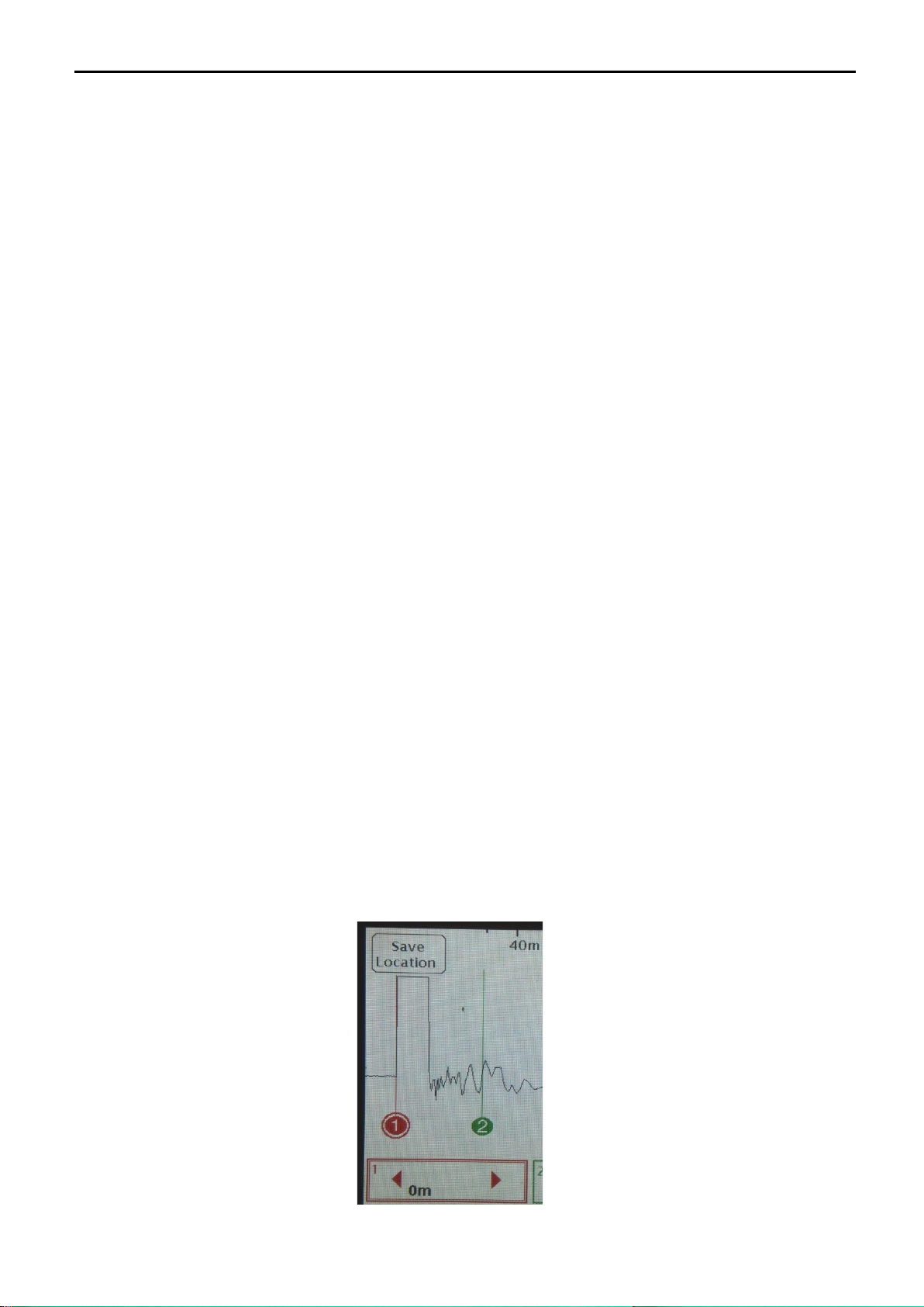
Position of the red cursor can be stored, e.g. if the user wants to work in the mode of “Cancel test lead length”.
1. Select the red cursor to adjust by touching anywhere inside the red zoom window.
2. Touch along the main waveform to move the cursor to the desired location.
3. Press “Save Location” button
4. The instrument will remember the position of the red cursor at the next switch on of the device.
Tracker Pro TDR Instruction Manual
Page 8of 44
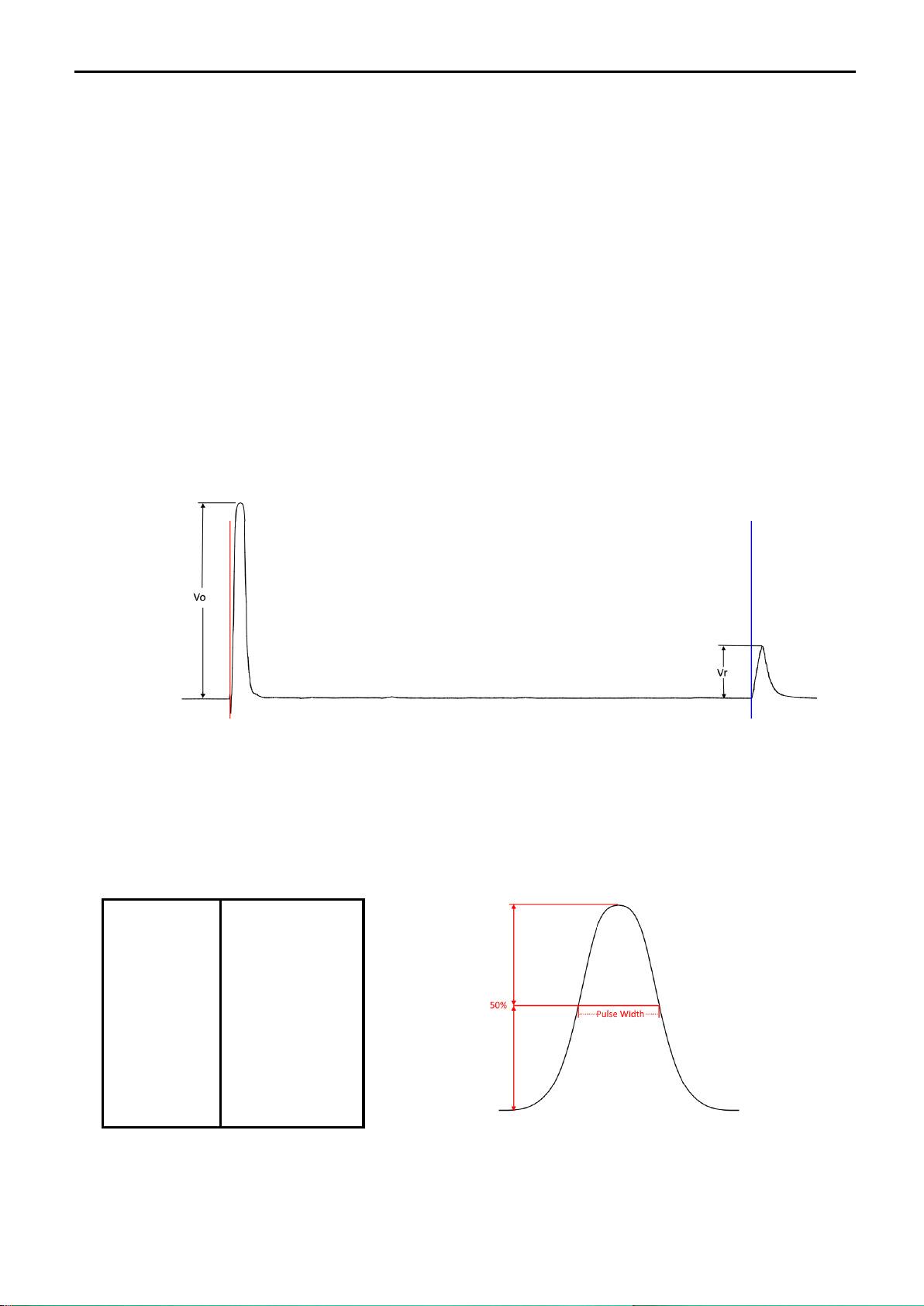
2.5 Return Loss
The green or blue ZOOM windows automatically display the distance between the red and the green or blue
cursor positions. At the same time, the Return Loss value is displayed there in [dB].
In general, Return Loss is the loss of power in the signal returned (reflected from any impedance mismatch in a
transmission line.
Basically, the lower the value of RL, the more severe the fault.
The dBRL value is usually expressed as a ratio in decibels (dB) an it is calculated and displayed to the TDR
user via the equation:
RL (dB) = 20log10(Vo/VΓ)
where:
RL(dB) is the return loss in dB
𝑉𝑂is the transmitted signal amplitude in Volts
𝑉𝑅is the reflected signal amplitude in Volts recorded at the TDR.
See Figure below for the visual TDR representation of these values.
In an ideal world where flawless transmission cables are used, the amount of reflected signal would match
the transmitted signal amplitude resulting in a dBRL reading of 0dB. Actual cables will have a given amount
of attenuation per kilometer that is also dependent on the fundamental frequency of the pulse that is
transmitted by the TDR. The higher the frequency (or inversely the lower the pulse width), the greater the
attenuation over distance will be. Additionally, this means that the shown dBRL value is a combination of
the fault on the cable and the cable attenuation.
Pulse Width
Fundamental
Frequency
2ns
250MHz
5ns
100MHz
20ns
25MHz
50ns
10MHz
100ns
5MHz
300ns
1.67MHz
500ns
1MHz
1000ns
500KHz
2000ns
250KHz

Tracker Pro TDR Instruction Manual
Page 9of 44
2.6 Pulse
Tracker Pro V3 has 9 available testing pulse widths:
2 nsec, 5 nsec, 20 nsec, 50 nsec, 100 nsec, 300ns, 500 nsec, 1000ns and 2000ns .
NOTE: 2 nsec pulse width of the Tracker Pro corresponds to the pulse width of less than 0,5 nsec
that is generated in any other known TDRs from other manufacturers.
The default pulse width for the Tracker Pro is 2 nsec. In order to change it, press the PULSE key and choose the
desired pulse width value on the slide bar below (press the screen on the correct position that corresponds to the
required pulse width). The choice made is presented in a pulse width key, eg. PULSE 50 nsec
NOTE: Always start the fault finding procedure in the shortest pulse width available, as the fault may be
only a short distance away. Use the Range and Vertical Gain controls to locate fault. If the fault is not
located, adjust to the next larger pulse width and retest.
2.7 Vertical Gain
The Vertical Gain control increases or decreases the vertical amplitude of the waveform display. Increasing the
vertical gain of the waveform display allows the user to see smaller reflections or minor faults on the cable
signature.
Tracker Pro has 6 available levels of Vertical Gain control:
1x/4x, 2x/8x, 4x/16x, 8x/32x, 16x/64x and 32x/128x
After the instrument switch on, a default level of Vertical Gain is applied - 1x/4x.
1. In order to change the Vertical Gain, press the V.GAIN key.
2. Select the required level of Gain by choosing the right key . 1x/4x, 2x/8x, 4x/16x, 8x/32x16x/64x or 32x/128x
The default value of the Vertical Gain can be set by the user - just go to MENU and select the required value of
the Vertical Gain at the “Settings” screen.
Tracker Pro TDR Instruction Manual
Page 10 of 44
2.8 Range
Range, or horizontal zoom, expands and contracts the waveform
from the left side. These are different preset range levels with the
first being the small, seeing up to 20 meters, and last- the largest,
seeing up to 4,000 meters down the cable. Once the proper range
has been selected the cursor zoom windows can be used to see
specific areas in the cable with finer detail.
The default value of the Range can be set by the user - just go to
MENU-Settings and set-up the appropriate position of the slide bar
1. In order to change the testing Range, press the RANGE key.
2. Adjust the required Range by the use of a slide bar.
2.9 Horizontal Position
The horizontal position arrows can be used to scan to the left and right on the cable without changing the range
level. You can use it to view the whole length of the tested network at the chosen pulsewidth in search of unusual
reflections that could be actual faults or expected regular points. The arrows can be held down to continuously
scan along the cable to the desired location.
2.10 VOP (Velocity of Propagation)
The speed of light in a vacuum is 300,000 kilometers per second. This speed is represented by the number 1(100%).
A coaxial cable with a VOP of . 85 would transmit a signal at 85% of the speed of light.
2.10.1 Determine VOP
The VOP number of a cable is determined by the dielectric material that separates the two conductors. In a coaxial
cable, the foam separating the center conductor and the outer sheath is the material determining the VOP. In
twisted pair, the VOP number is determined by the spacing between conductors and the insulation that separates
them.
The VOP of a cable can change with temperature, age and humidity. It can also vary from one manufacturer
and/or cable family and from one run to another. Even new cable can vary as much as +/-3%.
There are several ways to determine the correct VOP. The first is to simply refer to the VOP card provided with
the instrument. Second, consult the manufacturer for the correct VOP of that specific cable. A third way is to
actually determine the VOP from a known cable length:
1. Measure a known cable length, the longer the cable, the more accurate the VOP will be.
2. Correctly place the cursors of the TDR on the output pulse and the reflected pulse (end) of the cable.
3. Change the VOP setting until the “Distance Between Cursors” displays the known length.
2.10.2 Reducing VOP Error
When trying to pinpoint a fault, the most common technique used to reduce VOP error is to test the faulty cable
from both ends.
1. Determine the path of the cable and, therefore, its length
2. Test both ends of the cable to a common point on the cable (fault) with VOP readings
➢If the sum of the two readings is more than the known cable length, reduce the VOP setting and retest
➢If the sum of the two readings is less than the known cable length, increase the VOP setting and retest
3. Continue this method until the sum of the two readings equal the known length of the cable
4. The result will be the correct length readings.
2.10.3 Set up VOP for the Actual Cable Test
After the instrument switch on, a default value of VOP is applied, e.g. 85%
1. In order to change the VOP, press the VOP key.
2. Select the required value VOP by pressing up or down arrows on the screen
Tracker Pro TDR Instruction Manual
Page 11 of 44
The default value of the VOP can be set by the user - just press the key “Save Start VOP” and the actually
displayed VOP value will be the default value with the next switch on of the instrument.
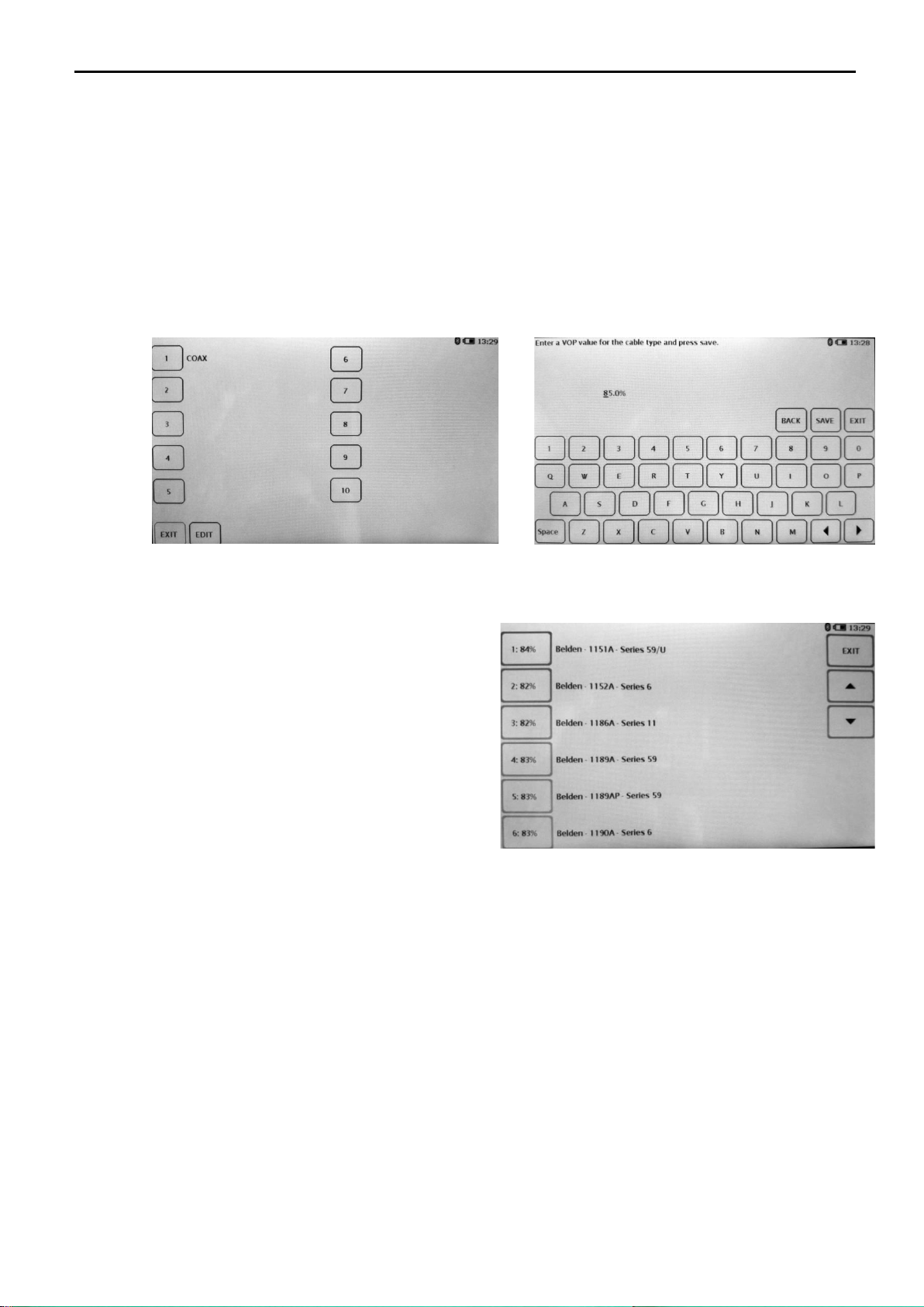
You can also use the feature “Favorites” –the user can store 10 favorite of the most frequently used VOP values
in the memory of the instrument.
1. Press VOP key
2. Press “Custom VOP List” key
3. A screen with 10 numbered boxes, „EDIT” and “EXIT” keys will be displayed.
4. Press „EDIT” key in order to determine where you want to store the preferred VOP value.
5. A screen with a keypad will be displayed.
6. Write down the name of your preferred VOP value and press “NEXT” key.
7. Write down the desired VOP value and press “SAVE” key.
8. You can edit the favorite VOP value any time or leave the screen by pressing „EXIT” key.
You can also use the feature “STD Cables” – the user can select the VOP value from the pre-stored list of the most
commonly cables used in the US.
1. Press VOP key
2. Press “STD Cables” key
3. Select the desired cable type and press „EXIT”
2.11 Filters
The filtering option is used for various types of interference.
1. Press FILTER
2. Select the required Filter value by choosing the right key . 1x, 2x, 4x, 8x, x16, 32x or 64x
3. The 8x filter will be the most accurate as it takes the average of the most waveforms.
Signals such as power (50 to 400 Hz), audio (100 Hz to 20,000 Hz), data (50 Hz to 10MHz), and RF (500 kHz to
1GHz) can all affect a TDR differently. Therefore, a TDR with only one type of filtering system may work well
in one application but not in another.
The Tracker Pro has 7 available levels of Filter control: 1x, 2x, 4x, 8x, x16, 32x or 64x.
Please, note, the higher filtering value, the slower the response of the waveform on dynamic changes in the cable
under test –e.g. performing shorts of opens at the end of the cable in order to confirm the correct location of the
cable end. Using the filter value No. 4 will enable to see the waveform going down and up in real time, whereas
any higher filter value will result in the delay of the waveform movement.
The default value of the Filters can be set by the user - just go to MENU and select the required value of the
Startup Filter Level at Settings.
Tracker Pro TDR Instruction Manual
Page 12 of 44
2.12 Auto-Search
The Auto-Search function is used for a quick test of the cable or for automatic search mode of the most severe
fault along the tested cable.
1. Press AUTO SEARCH.
2. The blue cursor moves to the largest impedance mismatch.
3. Markers are placed at possible events along the cable. The markers can be deleted by pressing the key “Erase
markers”
When the end of the cable is disconnected from the cable plant, the largest reflection will be the end of the cable
and therefore cursor No. 3 will move to the end. If not disconnected, the blue cursor will move to the largest
impedance mismatch on the cable line.
NOTE: The Auto-Search mode is working properly in a variety of different conditions but you just cannot
assume it works perfect in all of the situations. It’s only just a helping tool to the user.
NOTE: If you pressed the Auto-Search key on the Tracker Pro and the blue cursor pointed the place at
the leading edge of the pulse reflection from the point where the crocodile clips of test leads had
been connected to the cable under test, it DOES NOT mean there are no faults along this cable!
2.13 Menu
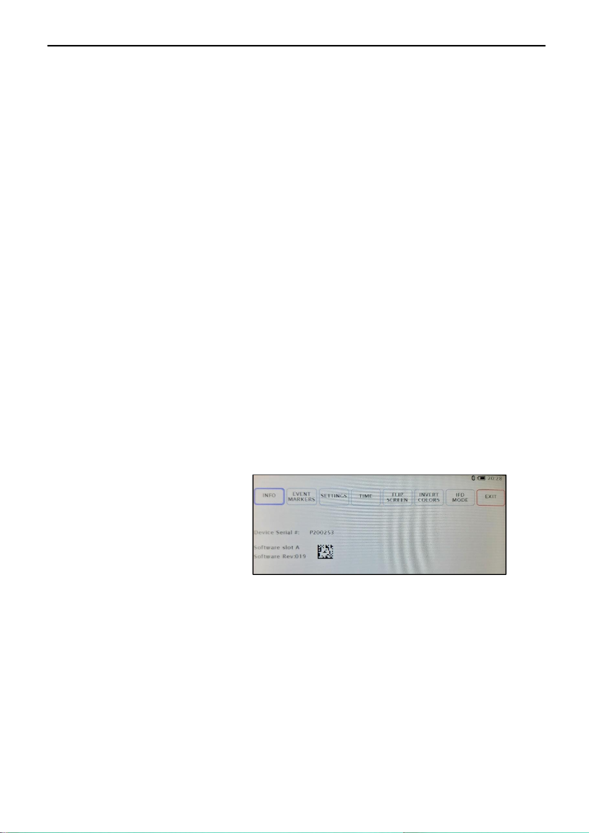
By pressing the MENU key, the user can enter the menu of the instrument including:
a) INFO page that presents information on the instrument serial number, actual software revision and bar
code containing serial No. info.
b) Event Markers (adjusting Auto Search Marker sensitivity)
c) SETTINGS mode (LCD screen brightness, distance measure units, VOP format, auto shut-off, Start-up
Vertical Gain, Start up Filter level and Active or Hidden ZOOM Windows)
d) TIME mode (adjusting the Time and Date)
e) FLIP SCREEN mode (flip of the screen by 180 degrees)
f) INVERT COLORS mode (invert of screen colors)
g) IFD Mode (Intermittent Fault Detection)
2.13.1 Internal Software Revision
The procedure of updating Tracker Pro firmware can be done only from a PC via the TrackerView application.
The TrackerView application is free of charge and can be downloaded from the manufacturer’s website.
The whole updating procedure is very easy and can be done by the user free of charge over the internet.
2.13.2 Event Markers
Allows the user to adjust the sensitivity of the Auto Search event markers.
1. Press the Menu buton
2. Press Event Markers
3. Press the selected value of the Auto Search Marker Sensitivity (level 1 –the smallest events up to level 5 –
the largest events along the cable length)
4. Press EXIT to leave the Menu screen
Tracker Pro TDR Instruction Manual
Page 13 of 44
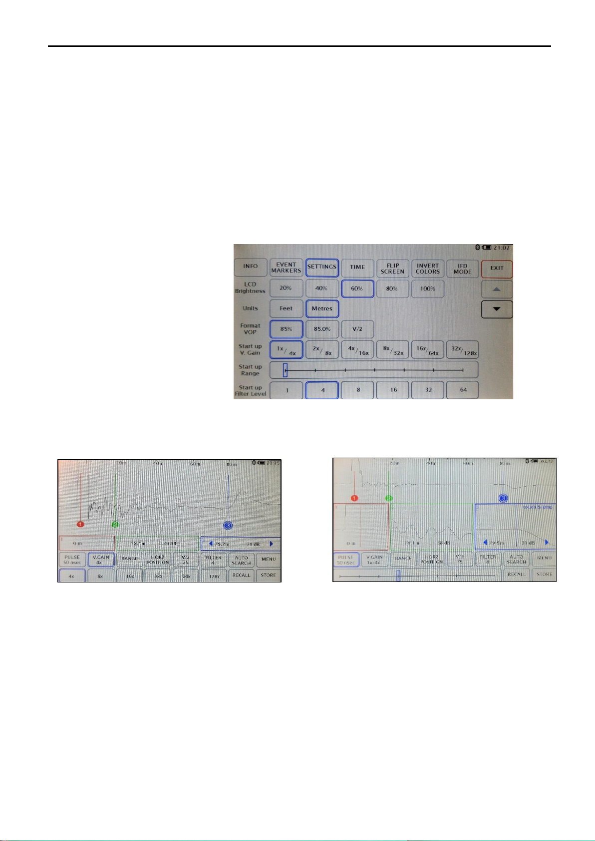
2.13.3 Settings
We can set up a few working parameters of the Tracker Pro in the MENU. This will set up the chosen values as
default ones for the switch on of the instrument.
1. Press MENU key
2. In order to select the desired LCD screen brightness, (LCD Brightness), chose one of available option:
20%, 40%, 60%, 80% or 100%
NOTE: The higher LCD brightness value used, the faster internal battery drainage time!
3. In order to select the desired distance measure units (Units), chose either „Feet” or „Meters”
4. In order to select the desired VOP format (VOP Format), chose either 85% or 85.5%):
5. In order to select the desired level of Range, set up the appropriate position of the slide bar
6. In order to select the start-up value of the Vertical Gain (Start-up V. Gain), chose one of the values:
1x/4x, 2x/8x, 4x/16x, 8x/32x
7. In order to select the start-up value of the Filter level, chose one of the values:
1, 4, 8, 16, 32, 64
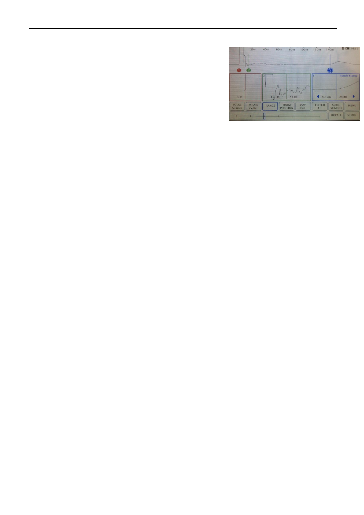
8. In order to select the option of hidden or active ZOOM windows (Zoom Windows), go to the second page
of the Menu by pressing the “down arrow” and select either „Active” or „Hidden”.
Main screen of the instrument:
- left –Zoom Windows hidden - right –Zoom Windows active
9. In order to select the option of automatic shut off (Auto Shut Off), go to the second page of the Menu by
pressing the “down arrow” and chose either “OFF” (no automatic shut off) or “10Min” (automatic shut off
after 10 minutes without touching the screen)
10. In order to control filtering option for incoming power lines interference “Filter 50Hz”, go to the second page
of the” Setting” Menu by pressing the “down arrow” and chose either “ON” (filters on), or “OFF” (filters off)
or “Auto Filter”(activating 50Hz filters when the unwanted 50Hz signal is detected by the instrument.

Tracker Pro TDR Instruction Manual
Page 14 of 44
11. In order to declare which selection of pulse widths will be saved on STORE action, please click on
the desired values until they are highlighted in blue frames.
Please, note, all the Tracker series TDRs have the unique „one-touch storage of all pulse widths”
feature as standard. The Tracker Pro V3 Model is the only one in which the user decides if all the
available pulse widths are being saved for future analysis or only the declared selection of them
will be available after the instrument is disconnected from the tested network.
12. Press EXIT to leave the Menu screen
2.13.4 Adjusting the Time and Date
1. Press MENU.
2. In the menu window, press TIME.
3. Using the number keypad enter the current time & date (NOTE: This device uses military time format).
4. Use the arrows to move left and right.
5. When the desired time and date is entered press SET.
6. Press EXIT to close the menu window and return to the main screen.
2.13.5 Flip Screen
Allows to invert the orientation of the display. This can be useful if you wish to hang the Tracker Pro from the
handle or prop it on its back.
1. Press MENU key
2. In the menu window, press FLIP SCREEN key
3. Press EXIT to close the menu window and return to the main screen.
2.13.6 Reverse colors
Allows the user to choose either a white or a black background.
1. Press MENU key
2. In the menu window, press INVERT COLORS key
Press EXIT to close the menu window and return to the main screen

Tracker Pro TDR Instruction Manual
Page 15 of 44
2.13.7 IFD Mode (Intermittent Fault Detection)
One of the problems on cables that is difficult to diagnose is the so-called “intermittent fault”. The fault of this
type often appears after heavy rains or windstorms and it is usually a series of high resistance faults. The Tracker
Pro TDR mode of IFD enables to pre-locate these type of faults regardless if they are shorts or opens.
In order to use the IFD mode efficiently, you need to:
1. Connect the Tracker Pro TDR across two cores of a cable that have been suspected of having problem with
intermittent fault..
2. Adjust all the on-screen parameters of the waveform in order to see details you need (set up Pulse, Range and
Vertical Gain).
3. Press “Mode” key on the main Menu
4. Press „IFD” key.
5. Select the desired sensitivity of the IFD testing on the level between 1 and 5
6. Activate the IFD testing on the cable that the TDR is connected to by pressing „START” key
7. Leave the main Menu by pressing „EXIT” key.
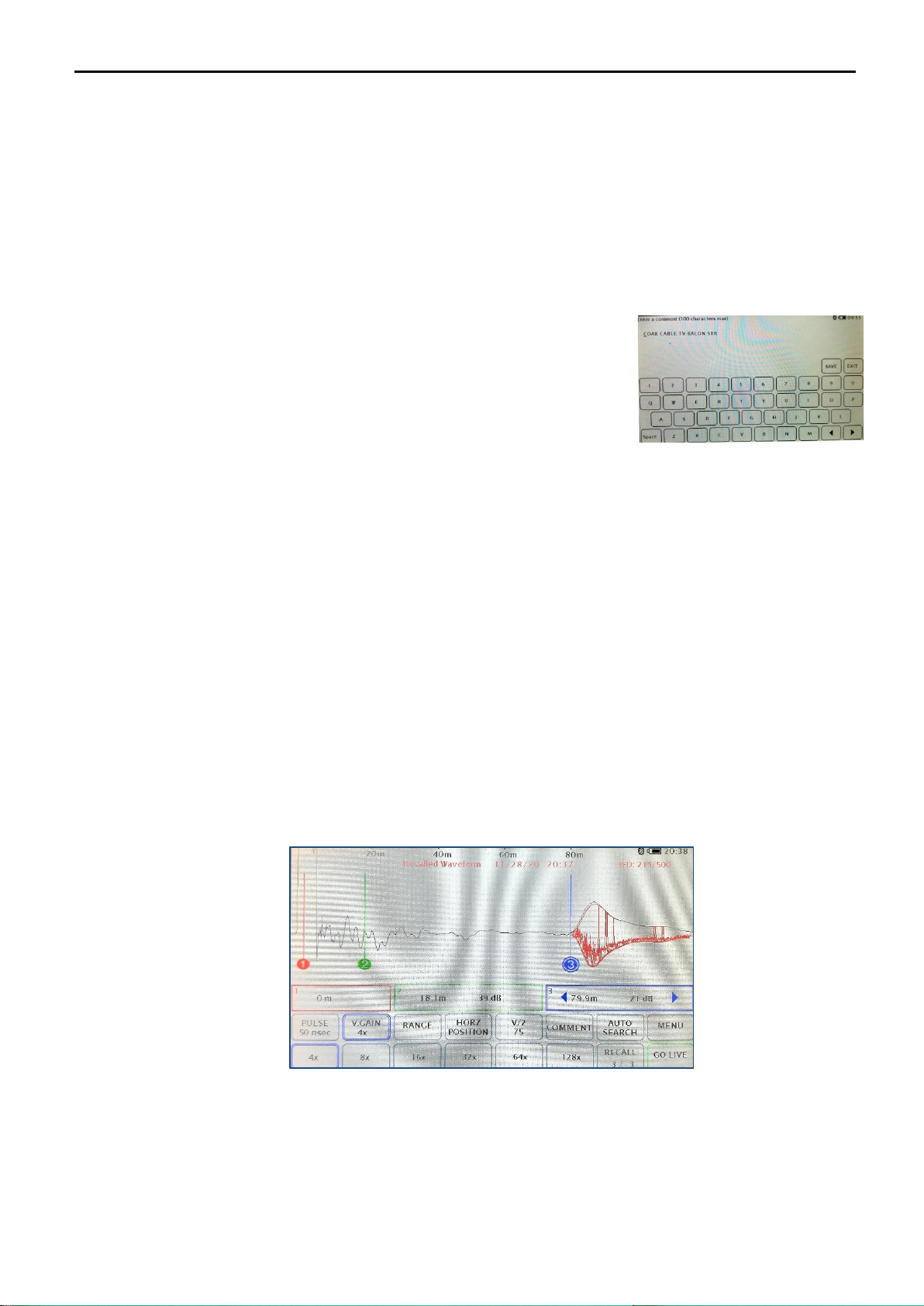
When you have activated the IFD mode, the TDR will record a baseline of the currently connected cable on the
pulse width that has been chosen by the user. It will then look for faults that deviate from that baseline waveform.
Any fault detected will be recorded as a red line overlayed on the base line (the more events found, the more red
lines). The IFD mode of Tracker Pro will record up to 500 faults that occur on the currently activated pulse width.
The actual number of the events (faults) that have been recorded will be presented on the upper part of the screen,
e.g. “IFD: 189/500”.
NOTE: The Tracker Pro TDR enables you to record intermittent faults on the cable only on individual pulse
widths such as 2 nsec, 5 nsec, 20 nsec, 50 nsec, 100 nsec, 300ns, 500 nsec, 1000ns and 2000ns.
When you switch a new pulse width it will record a new baseline waveform and continue to record red lines of
appearing faults. It will keep recording any faults that it sees on each pulse width up-to 500 total faults.
More detailed IFD data of the total number events (faults) recorded for the declared pulse widths will be
presented on the IFD Mode Control screen. Just press “Menu” key followed by pressing “IFD Mode” key
Tracker Pro TDR Instruction Manual
Page 16 of 44
Press the “Exit” key to come back to IFD recording mode
NOTE: Do NOT exit IFD mode at his stage in order not to lose your measurement data!
When you have finished your IFD mode session on all the required pulse widths, you can store the waveform as
you normally do - just press “STORE” key on the main screen. All pulse widths will then be recorded and all of
the faults will also be recorded. All the intermittent faults recorded can be then recalled and can also be viewed
on the Tracker Pro display or transferred for viewing on the TrackerView PC application.
When viewing a recalled IFD waveform you can add comments to the file recorded. The user can do it any time
until the record is deleted or overwritten.
1. Press RECALL
2. Select the desired waveform form the Memory Content screen
3. Press “Comment”
4. Key in the text you wish to save
5. Touch “Save” to store the comments with the waveform
6. Touch “Exit” to discard
7. Press GO LIVE to leave the area of internal memory of the TDR
NOTE: Any comment that has been entered by the user will be visible for the procedure of transferring the
data to a PC (data transfer screen). The comment will be transferred with the file and the user can find
it in the Comment area on the TrackerView screen while viewing the waveform on a PC.
In order to exit from the IFD mode
1. Press “Mode” key on the main Menu
2. Press „IFD” key.
3. Press „STOP” key
You can also start another IFT testing session by pressing “RESTART” key on this screen.
Recall of IFD data from the Tracker Pro’s memory
The stored IFD data will be presented as a baseline of the tested cable at the pulse width that has been chosen by
the user including overlayed red lines of the events/faults that have been recorded during IFD testing. You can
analyze such IFD data when you open the file from the memory screen on the Tracker Pro. Please, note you can
see the IFD data only on the pulse widths that have been previously declared during the IFD testing stage, the
waveform at other pulse widths will display the base line only.
NOTE: Due to its nature, IFD testing can take some time. In order not to lose the measurement data due to the
internal battery run time level, please, make sure you control the charging status of the battery. You can always
activate IFD mode with the charging procedure on (the active use of the TDR during the charging procedure from
the 230 V AC mains or from the external power generator).

Tracker Pro TDR Instruction Manual
Page 17 of 44
2.14 Internal Memory
2.14.1 Storing of Waveforms
1. Connect the cable under test to Tracker Pro
2. Press STORE
3. Wait a moment, until the icon returns to the word STORE, for Tracker Pro to save the cable at all pulse widths.
4. When storing, the button will show the word “Storing” and the indication of the memory cell where the
measurement is actually being stored, e.g. “6/10” plus a “progress bar” of the storing operation. When
finished storing the button will return to showing the word “Store”. After storing, you can disconnect the
cable and work remotely or download to your PC or a mobile device.
5. The Tracker Pro is able to store up to 60 waveforms. Once 60 waveforms have been stored the Tracker TDR
will start replacing the oldest waveform with the newest.
Please, note, all the Tracker series TDRs have the unique „one-touch storage of all pulse widths”
feature as standard. This means that the instrument will save all pulse widths available for the model
used regardless of what is actually seen on the screen. Each file is approximately 1 MB.
The Tracker Pro V3 Model is the only one in which the user decides if all the available pulse widths
are being saved for future analysis or only the declared selection of them will be available after the
instrument is disconnected from the tested network.
2.14.2 Saved Waveforms
All the measurement data recorded into the Tracker Pro’s internal memory can be recalled at any time for some
more careful or advanced analysis. You can view the whole trace of the testing pulse along the cable at all available
pulse widths no matter how was the setting of the screen at the time of storing. Each file can be transferred to a
PC with the use of the USB cable for further analysis, printing or with the purpose of using it as a
Template/Reference waveform to be compared with some other waveforms recorded on the same section of a
cable later on. It can also be transferred to a mobile device such as tables or smartphone with the use of Bluetooth
communication or a micro-USB cable (only Android powered devices) with the purpose of, e.g. sending the
measurement data to an office for urgent comparison with the Template/Reference waveform of to a customer
in a PDF format
2.14.3 Procedure of Viewing Saved Waveforms
1. Press RECALL in order to open the Memory Content screen
2. Select the desired waveform –each of them can be identified by a number of the memory cell where the
measurement has been actually stored, date and time of storing and description of the file (only if the user
has entered such description)
3. On the right side of the screen, the user can see the Exit button (coming back to the main screen), arrows to
scroll the memory content screen up and down and the Delete All button to initiate the 3-step procedure of
erasing the instrument’s measurement data memory.
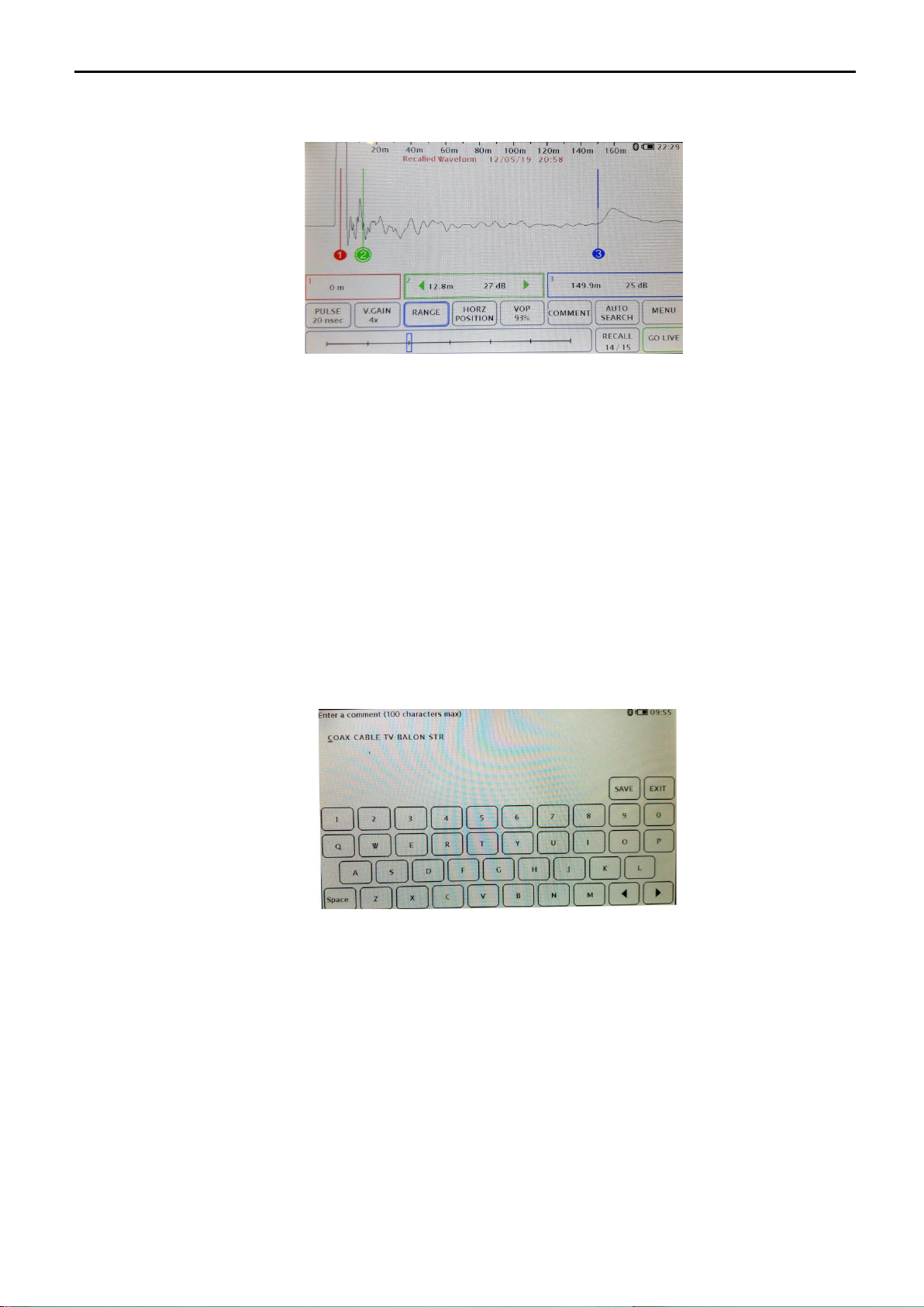
Tracker Pro TDR Instruction Manual
Page 18 of 44
The recalled waveform contains information on the date and time when it was stored. The information in red is
displayed at the upper part of the screen
At this time, you can change the parameters of the presented waveform such as the pulse width, vertical gain,
range and VOP. You can move all the 3 cursors and measure distances to multiple events on the cable.
NOTE: While viewing the recalled waveforms, the key RECALL has changed into GO LIVE. Pressing
this key results in leaving the area of internal memory of the TDR and going back to the live
waveform under test (if any testing is actually being done).
2.14.4 Editing Comments
When viewing a recalled waveform you can add comments to each of the recorded measurements. The user can
do it any time until the record is deleted or overwritten.
8. Press RECALL
9. Select the desired waveform form the Memory Content screen
10. Press “Comment”
11. Key in the text you wish to save
12. Touch “Save” to store the comments with the waveform
13. Touch “Exit” to discard
14. Press GO LIVE to leave the area of internal memory of the TDR
NOTE: Any comment that has been entered by the user will be visible for the procedure of transferring the
data to a PC (data transfer screen). The comment will be transferred with the file and the user can find
it in the Comment area on the TrackerView screen while viewing the waveform on a PC.
2.14.5 Deleting of Waveforms from the TDR
The user can clear the internal memory of the Tracker Pro, e.g. before going out for a series of cable tests that
require storing a large number of measurements. Deleting all the recorded files in such a case would ease
identification of the newly recorded data.
NOTE: DELETING ALL feature of the Tracker Pro is IRREVERSIBLE!
However, the procedure goes in 3 steps and the user is receiving clear warnings before the
measurement data are actually and irreversibly lost.

Tracker Pro TDR Instruction Manual
Page 19 of 44
The actual procedure of clearing the Tracker Pro’s memory is the following:
1. Press RECALL if you are on the main screen
2. Press Delete All on the Memory Content screen (right- hand corner of the screen)
3. Select the desired option: „DELETE ALL” (clear all the internal memory) or „CANCEL”(to stop the
deleting procedure).
4. If you have pressed DELETE ALL, the next step is to confirm your wish to continue the procedure of deleting
all the measurement data by pressing YES or you pressing NO (to stop the deleting procedure).
NOTE: Finalizing the DELETE ALL procedure for the Tracker Pro results in deleting all measurement
data that have been recorded so far in the internal memory of the instrument. As soon as the
DELETE ALL procedure is completed, the key RECALL on the main screen is inactive as there
are no waveforms in the instrument’s memory.
2.14.6 Downloading of Saved Waveforms into a PC
1. Connect Tracker Pro to your PC using a USB cable.
2. On your PC, open the “Tracker View”application.
3. Turn on the Tracker Pro.
4. Select “Download from Instrument” option by pressing the key in the right-up corner of the screen.
5. Select the file or files to download.
6. A progress bar will close when the download is complete and the file has been moved to your Tracker
View folder on your PC.
NOTE: If you download a single file from your Tracker Pro, the waveform will be displayed on the PC
screen and the file will be automatically stored on your PC (a default folder is TrackerView). If
you download more than on file at the same time, all the selected files will be stored on your PC
(a default folder is TrackerView) but none of them will be displayed on the PC screen after the
data transfer.
NOTE: All the files are being transferred to a PC in a “raw format”, that is, without the proper values of
Pulse or Range, even if the user has set up those values on the Tracker Pro screen.
Tracker Pro TDR Instruction Manual
Page 20 of 44
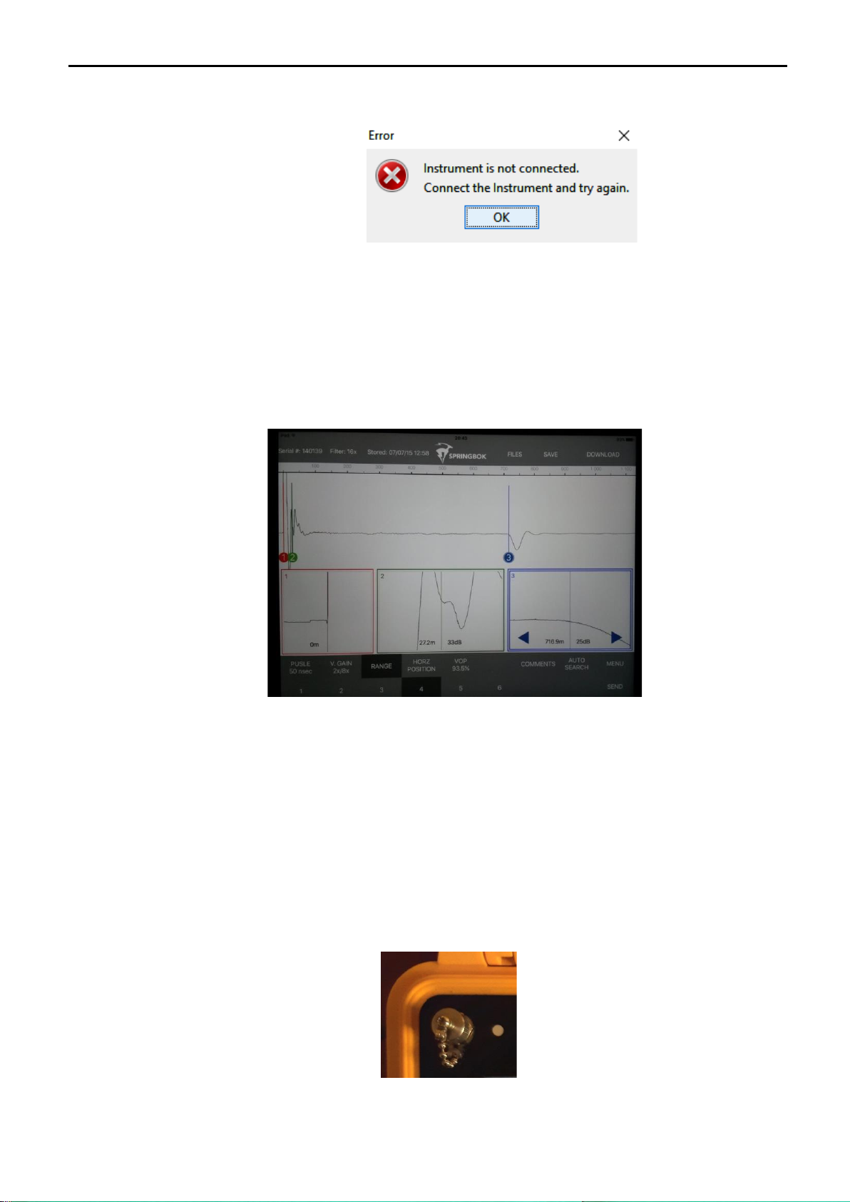
NOTE: In case of any problems with communication between the Tracker Pro TDR and the PC, an Error
message will appear:
2.14.7 Downloading of Saved Waveforms into a Mobile Device
1. Open the Tracker View App on your iPhone or Android device.
2. Turn on the Tracker Pro (must have Bluetooth, not available on all models)
3. Touch “Download” on your smart device.
4. The smart device is scanning for the TDR (no other devices can be paired such as headphones).
5. Select the TDR by touching the serial number displaying on your smart phone device and touch “Connect”.
6. Select the waveform you wish to download and touch “Download”. A progress bar will display the
waveform.
3. Charging the Batteries
The Tracker Pro is powered by a rechargeable battery pack contained within the instrument.
When the battery supply has been depleted and the batteries need to be recharged, plug the external battery
charger into the front panel charger socket and into any common AC outlet. The front panel green LED will light
to indicate the batteries are being charged. The LED indicator will stay illuminated while the charger
is plugged in.
The Tracker Pro will operate while being charged as long as the battery level indicator is above a quarter charge.
Allow at least 5 hours charging time for the batteries to cycle from a completely discharged state to a fully charged
state.
Table of contents
Popular Industrial Equipment manuals by other brands


Conductix-Wampfler
Conductix-Wampfler 1400 Series manual

ShopBot
ShopBot PRS Assembly guide

Emerson
Emerson PACSystems RX3i Important product information

Porvair Sciences
Porvair Sciences Ultravap Mistral User instruction manual

Woodstock
Woodstock SHOP FOX D3348 instruction sheet

Nakanishi
Nakanishi NR3060-AQC Operation manual