AESSEAL SWFF-TF Guide

YDR-SWFF-TF-16 06/2019
SWFF-TF Range
Installation, Operation & Maintenance Instructions
YDR-SWFF-TF-16 06/2019
Health and Safety
●This system has been designed for use only as a barrier fluid system for mechanical seals using a
suitable non-hazardous barrier fluid.
●Isolate the process and power on installation, maintenance and decommissioning and ensure that the
system pressure has been relieved before undertaking maintenance.
●The system should only be installed by competent engineering personnel
●Electrical connections must be made in compliance with applicable legislation and / or local requirements
by a competent / qualified electrician.
●If there is any risk of FIRE the system must be fitted with a suitable pressure relief device to prevent over-
pressurisation.
●Pipe relief valves discharge to safe area (when fitted).
●Pressure test the complete system assembly at 1.1x maximum working pressure (duration 5 minutes) and
ensure the system is completely leak free before full operation.
●Do not over-pressurise the system beyond the maximum design pressure. If there is any possibility of
over-pressurisation, the system must be fitted with a suitable protection device.
●Do not exceed the operating limits of the system. Not designed for cyclic loading.
●The system may get hot in operation with risk of burn injury, and suitable engineering controls or guarding
should be adopted where necessary. The risk from Legionella bacteria should be assessed with water
barrier fluids at temperatures between 20°C to 45°C (68°F to 115°F).
●If the barrier fluid becomes contaminated it is recommended that the barrier fluid is replaced taking
necessary precautions. If the contamination is potentially corrosive or damaging to the system remove
from service and contact AESSEAL for technical advice.
Environment
Once the barrier fluid and system have reached the end of its life, it should be disposed of in accordance with local
regulations and with due regard to the environment.
For further information please contact AESSEAL®
YDR-SWFF-TF-16 06/2019
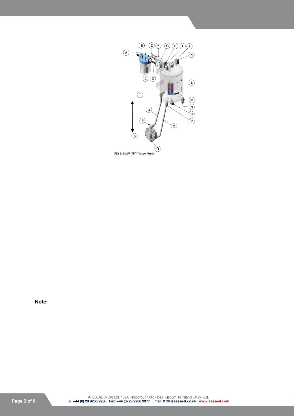
Fig. 1 SWFF-TF Vessel Guide
Installing & Commissioning
Components
AIn-line Filter Feed Connection
BIn-line Filter (UV stabilized materials)
CIn-line Filter Output Connection
DFlow Fuse Inlet Connection
EWater Regulator
FFlow Fuse Block
GPressure Gauge
HFlow Indicator & Fill Button
IAuto Re-set Adjustment Screw
JSpare Connection
1. Connect the Flow Fuse Block assembly (F) to the vessel as follows :
a. Push the 12mm OD tube fully into the elbow compression fitting and tighten the elbow nut by hand (‘finger-
tight’).
b. Tighten the elbow nut 1.1/4 turns with a suitable tool.
If the connection leaks on test, depressurise the system and further tighten the elbow nut slightly (only a
little at a time).
2. Install the System in a suitable location, which is free from vibration and within the following distances :
a. A minimum of 60cm (24”) above the mechanical seal.
b. A maximum of 2 metres (80 inches) above and 1 metre (40 inches) from the side of the mechanical seal (S). If
your vessel has a cooling coil, refer to Table 1 for commissioning details.
3. Isolate the plant water supply. Connect the vessel from the seal supply connection (P) to the mechanical
seal (S) and from the mechanical seal (S) to the seal return connection (T) using the two lengths of tubing
provided. To prevent the compression fitting crushing the Nylon tubing (and possible leakage) push the
metal tube insert (supplied) fully into the end of the tubing (right up to the shoulder on the insert). It is
imperative that the return line from the seal (S) to the seal return connection (T) does not sag. If installing
finned tubing please refer to Table 2.
2m (80”) maximum
60cm (24”) minimum
1m (40”)
maximum
KAuxiliary Fill Connection
LPressure Vessel
MRelief Valve
NRelief Valve Adjuster Cap
OVessel Drain Connection
PSeal Supply Connection
QSupply / Return Pipe
RSeal Fittings
SMechanical Seal
TSeal Return Connection

YDR-SWFF-TF-16 06/2019
4. Connect the water line to the in-line filter feed connection (A) and from the in-line filter output connection
(C) to the Flow Fuse inlet connection (D). Note that the maximum input pressure of the in-line filter (B) is 8
bar / 116 psi. If the water line pressure feeding the in-line filter is above 8 bar / 116 psi we advise that you
use a regulator to reduce this water pressure to below 8 bar / 116 psi before it reaches the in-line filter (B).
Note that the maximum temperature the inline filter can withstand is 50ºC / 122ºF.
5. Release the cap on the black regulator adjustment (E) and rotate it fully counter clockwise.
6. Before filling the vessel with barrier fluid, disconnect the return pipe (Q) at the seal return connection on
the vessel (L). This will allow any trapped air to escape out of the seal.
7. Turn on the plant water supply and fill the vessel by rotating the regulator handle clockwise (E) and
holding in the red Flow Fuse fill button (H) until barrier fluid is seen at the end of the seal return pipe (Q).
When barrier fluid is seen release the red Flow Fuse fill button (H).
8. Re-connect the seal return pipe (Q) to the vessel seal return connection (T).
9. Keep the red button (H) pressed in and turning the regulator handle (E) until the desired barrier pressure is
achieved.
10. Ocne the desired barrier pressure is achieved, release the red button (H), which should stay depressed.
Set Relief Valve Relieving Pressure
11. The working pressure of the relief valve (M) must be set before the working pressure of the system (the
working pressure of the relief valve should be 1 bar / 14.5 psi above the System working pressure). The
operating parameters of the relief valve are 5 - 10 bar / 72.5 - 145 psi (maximum relief valve set pressure
10 Barg / 145 psig).
12. Unscrew the relief valve adjuster cap (N) fully anti-clockwise.
13. Press and hold in the red Flow Fuse fill button (H) for approximately 3 minutes to fill the vessel. When the
vessel is filled, rotate the black Flow Fuse regulator adjustment (E) clockwise, until the desired relieving
pressure of the the relief valve is seen on the pressure gauge (G).
14. Screw the relief valve adjuster cap (N) clockwise until the Relief valve (M) starts to leak.
15. At this point stop turning the relief valve adjuster cap (N), and lock it using the lock nut. This is now set as
the relieving pressure for the system.
If the relief valve has been factory pre-set the set pressure will be detailed on the nameplate.
Set the Flow Fuse Barrier Fluid Pressure
16. Open the drain valve (O) for 2 minutes to drain the vessel.
17. Repeat installation and commissioning steps 5 –8.
18. Press and Hold in the red Flow Fuse fill button (H) for approximately 3 minutes to fill the vessel. When the
vessel is filled rotate the black Flow Fuse regulator adjustment (E) clockwise until the desired barrier fluid
pressure is seen on the pressure gauge (G). Please note that the Flow Fuse is at its optimum operating
condition when the barrier fluid pressure is set 2 bar / 30 psi above stuffing box pressure (to a maximum
regulator set pressure of 6 Barg / 87 psig).
19. Once the desired pressure is shown on the pressure gauge (G) close the black regulator adjustment cap
(E). Slowly release the red Flow Fuse fill button (H). The red Flow Fuse fill button should be level with the
Flow Fuse casing. **
20. For direction of flow details please refer to Table 3.
that the Flow Fuse has two operating modes:
a. Manual Re-Set mode –The Re-Set mode adjuster (I) will be screwed completely in. In this mode the Flow
Fuse will completely shut off the plant water supply upon any seal failure. To reset the Flow Fuse press the red
button (H).
b. Auto Re-Set mode –The Re-Set mode adjuster (I) will be screwed counter clockwise. In this mode the Flow
Fuse will re-establish operating conditions after seal failure by allowing a small flow of water from the plant water
supply back into the vessel. The amount of flow will depend on how far the Re-Set mode adjuster (I) is screwed
counter clockwise (4 full turns counter clockwise sets the Flow Fuse in full Auto Re-Set). The Flow Fuse comes
factory set in Auto Re-Set mode.
YDR-SWFF-TF-16 06/2019
Relief Valve
●The relief valve (M) is fitted to limit any pressure build up due to excessive heat developing in the barrier
fluid.
●When pressure increase is detected the relief valve will trigger and relieve the excess pressure in the
vessel.
●With the Flow Fuse in Auto Re-Set mode, the pressure drop will be detected and colder water from the
plant water supply will be allowed to enter the vessel and replace the warmer water lost.
●The original working pressure of the vessel will be re-established automatically with the Flow Fuse in Auto
Re-Set mode.
Table 1: Cooling Coil
Connect the water supply to one of the cooling coil ports, inlet or outlet can be used, once the inlet has been connected,
pipe the outlet to drain. Turn the cooling coil water supply on.
Table 2: Finned Tubing
●Install the supplied lengths of finned tubing by connecting one length to the seal supply connection (P)
and the other to the seal return connection (T) on the vessel (L) *.
●The end user supplies and connects the hard pipe from the seal to the finned tubing.
*Finned tubing can be bent to suit the application.
Table 3: Direction of Flow
When the system is first run, check the direction of flow –i.e. which pipe gets hot. The hot pipe must go to the seal return
connection (T) on the vessel (L), or flow may cease. If the flow is incorrect, reverse the connections at the seal or vessel.
Optional Extra’s Installation/ Commissioning
If you have purchased an optional extra please refer to the installation instructions supplied with it.
For further information please contact AESSEAL®
Maintenance
The system should be maintained in accordance with site standards.
Daily
●Check for leaks and barrier fluid pressure & temperature.
Annually
●Check and examine the system for leaks and deterioration.
5 years
●Complete a full internal and external inspection of the vessel and all system component parts.
10 Years
●The system / vessel should be subjected to a complete and thorough examination, including the undertaking
of a full system hydrostatic proof pressure integrity test by a suitably qualified and competent person*.
AESSEAL recommends this should form part of the written scheme of examination as per the PSSR 2000
regulations.
* AESSEAL offers a full examination, integrity testing and refurbishment service (or, where necessary, a replacement system / vessel), to
ensure continued optimum and safe system performance.
YDR-SWFF-TF-16 06/2019
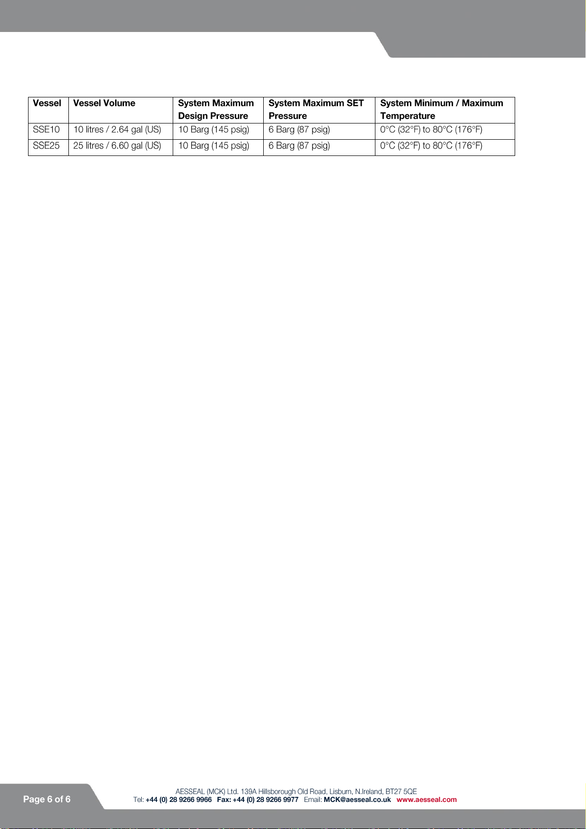
System Details
Minimum Piping / Hosing Specification
●10 bar / 145 psi at 80°C / 176 °F (minimum temperature 0°C /(32°F)
Vessel Design Code
●ASME VIII Div.1
Complies with Pressure Equipment Directive (2014/68/EU)
Table of contents
Other AESSEAL Industrial Equipment manuals


