Aimco AcraDyne iEC Gen IV User manual

Gen IV iEC Controller Operation Manual
10000 SE Pine St., Portland, OR 97216 • 800-852-1368 • 503-254-6600 • Fax 800-582-9015
www.aimco-global.com

2
AcraDyne Gen IV iEC Controller Manual
Table of Contents
1. Safety Information . . . . . . . . . . 3
2. Controller Diagram . . . . . . . . . . 4
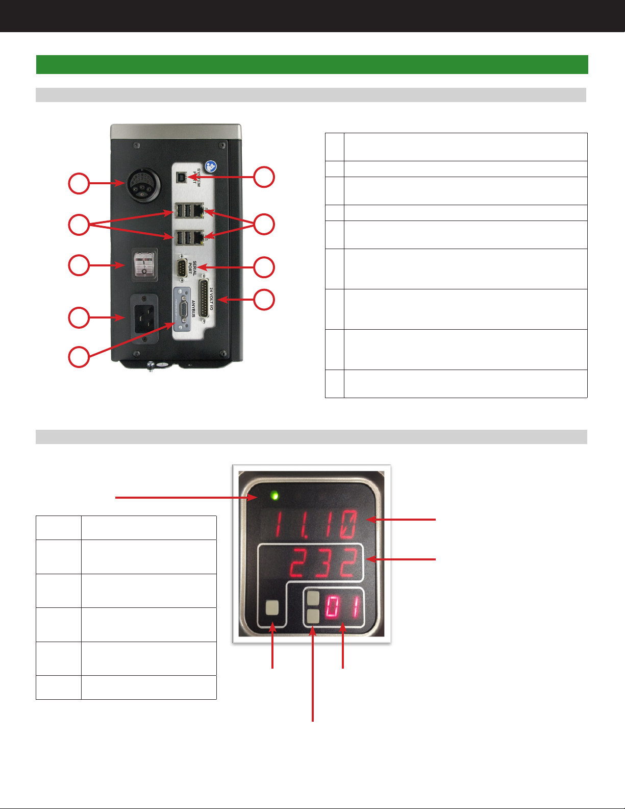
2.1 Bottom Panel . . . . . . . . . . . 4
2.2 Front Console LED Display . . . . . . . 4
3. Initial Setup. . . . . . . . . . . . . 5
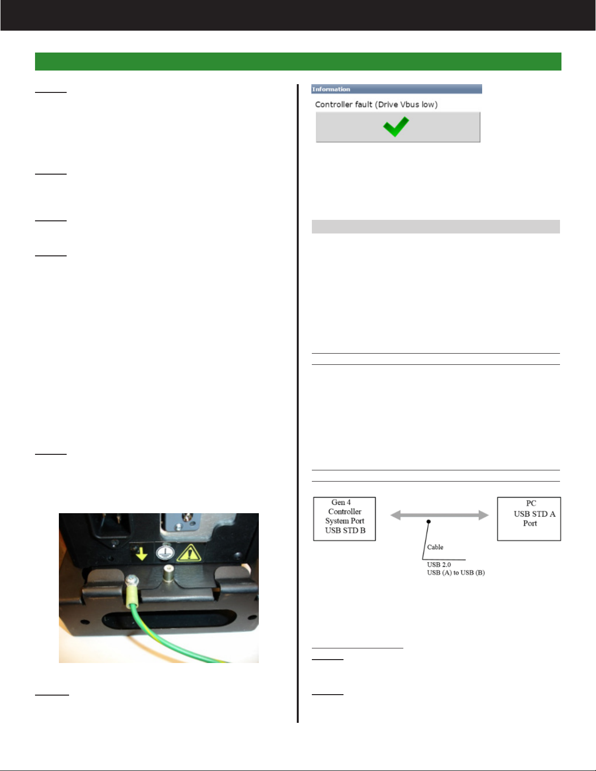
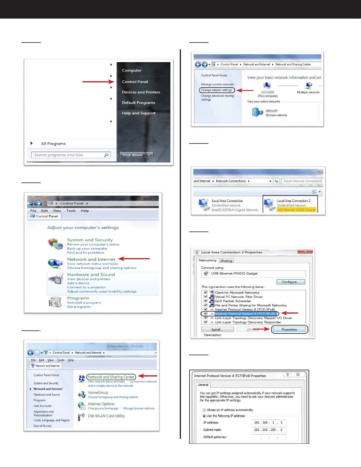
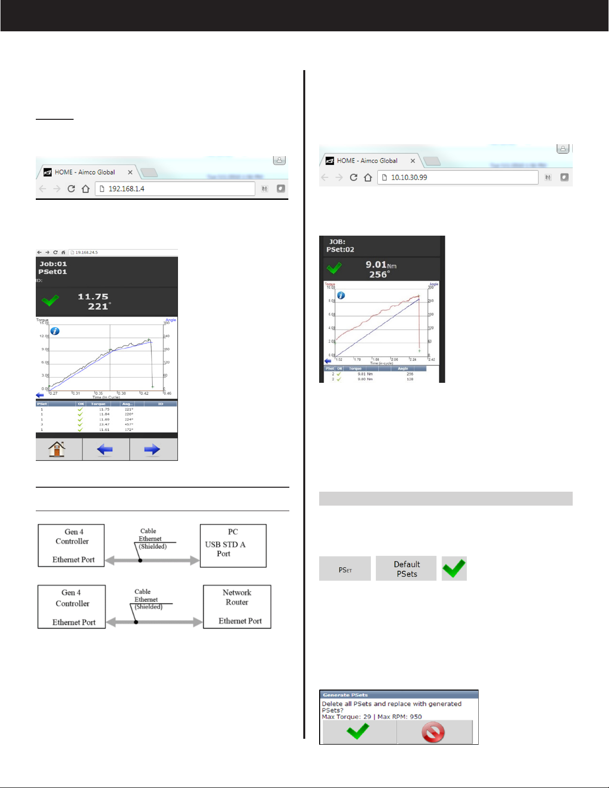
3.1 Connecting to the Controller . . . . . . 5
3.2 Quick Set Up (Default PSets from Tool). . . 7
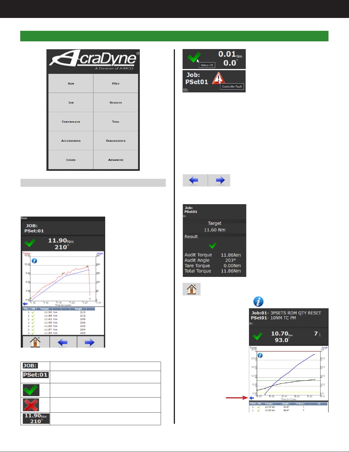
4. Home Page (Main Menu) . . . . . . . . 8
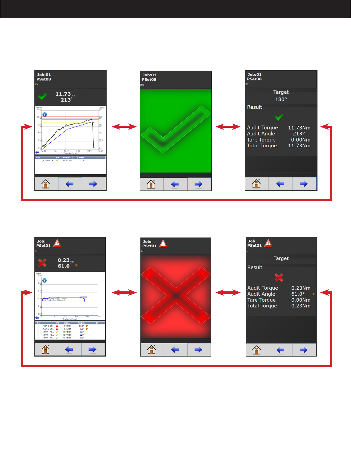
4.1 Run . . . . . . . . . . . . . . 8
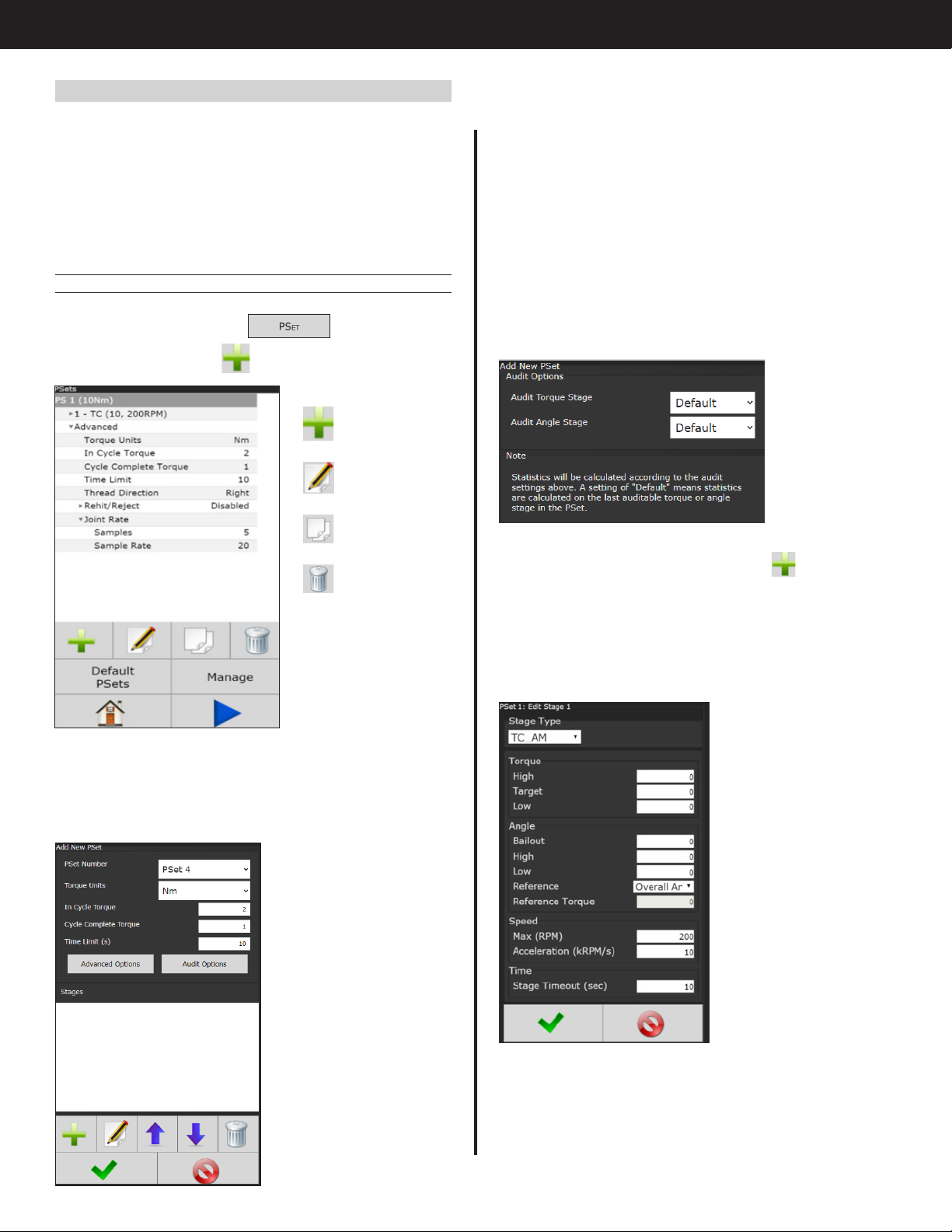
4.2 PSet . . . . . . . . . . . . . . 10
4.2.1 Add New PSet . . . . . . . . . 10
4.2.1.1 Add New Stage . . . . . . . . . 10
4.2.1.2 AcraDrive Discontinuous Drive Mode Settings 11
4.2.2 PSet Stages . . . . . . . . . . 14
4.2.2.1 TC Torque Control Stage . . . . . . 14
4.2.2.2 TC_AM Torque Control Angle Monitor Stage 15
4.2.2.3 AC_TM Angle Control Torque Monitor Stage 16
4.2.2.4 TC_AC Torque Control Angle Control Stage 17
4.2.2.5 Yield Control Stage . . . . . . . . 18
4.2.2.6 Delay Stage . . . . . . . . . . . 19
4.2.2.7 Unfasten Stage . . . . . . . . . . 19
4.2.2.8 Ergo Stop Stage . . . . . . . . . 20
4.2.2.9 Brake Stop Stage . . . . . . . . . 20
4.2.2.10 AC_TA Angle Control Torque Averaging
Stage . . . . . . . . . . . . . 21
4.2.2.11 AC_TCOMP Angle Control Torque
Compensation Stage . . . . . . . 22
4.2.2.12 AC_TCOMP Display of Torque
Compensation Value . . . . . . . 22
4.2.2.13 Sync Stage . . . . . . . . . . . 23
4.2.2.14 Thread Forming Stage . . . . . . . 23
4.2.2.15 Homing Stage . . . . . . . . . . 24
4.2.2.16 AC_TM Anti-Necking Stage . . . . . 25
4.2.2.17 Rate_Control Stage . . . . . . . . 26
4.2.3 Edit PSet . . . . . . . . . . . 27
4.2.4 Advanced Options. . . . . . . . 27
4.2.5 Default Psets . . . . . . . . . . 28
4.2.6 Manage PSets . . . . . . . . . 28
4.2.7 Multistage Rundown Evaluation and
Reporting . . . . . . . . . . . 29
4.2.8 Multiple Stage Rundown Examples . . 30
4.3 Job . . . . . . . . . . . . . . 31
4.3.1 Add New Job . . . . . . . . . 31
4.3.1.1 Advanced Options . . . . . . . . 31
4.3.2 Jobs "Enabled" Display and Button
Function . . . . . . . . . . . 32
4.4 Results . . . . . . . . . . . . . 32
4.4.1 Saving Rundown(s) . . . . . . . 33
4.5 Controller . . . . . . . . . . . . 34
4.5.1 Tool Setup . . . . . . . . . . . 34
4.5.1.1 Lock Tool On Reject . . . . . . . . 34
4.5.1.2 Buzzer . . . . . . . . . . . . . 35
4.5.1.3 Lights . . . . . . . . . . . . . 35
4.5.1.4 Start Input. . . . . . . . . . . . 35
4.5.1.5 MFB (Multi-Function Button) . . . . . 36
4.5.1.6 Disassembly . . . . . . . . . . . 37
4.5.1.7 Tubenut . . . . . . . . . . . . 38
4.5.1.8 Past Due Service Calibration . . . . . 38
4.5.2 IO . . . . . . . . . . . . . 39
4.5.2.1 Physical IO . . . . . . . . . . . 39
4.5.2.2 Physical IO Monitor . . . . . . . . 39
4.5.2.3 Anybus/Modbus TCP/Ethernet IP Inputs . 40
4.5.2.4 Anybus/Modbus TCP/Ethernet IP Outputs. 41
4.5.3 Communication Interfaces . . . . . 42
4.5.3.1 Ethernet/Second Ethernet . . . . . . 42
4.5.3.2 System Port . . . . . . . . . . . 42
4.5.3.3 Serial Port . . . . . . . . . . . . 42
4.5.3.4 Anybus . . . . . . . . . . . . 43
4.5.3.5 Spindle USB Port . . . . . . . . . 43
4.5.3.6 Serial USB . . . . . . . . . . . . 45
4.5.4 Protocols . . . . . . . . . . . 45
4.5.5 Front Panel Buttons. . . . . . . . 45
4.5.6 Power Up . . . . . . . . . . . 45
4.5.7 Bar Code Setup . . . . . . . . 46
4.5.8 Set Time . . . . . . . . . . . 47
4.5.9 Remote Connections . . . . . . . 47
4.5.10 Master Spindle Setup . . . . . . . 47
4.5.10.1 Setting up Multi-Spindle Network . . . . 47
4.5.11 Languages . . . . . . . . . . 47
4.6 Tool . . . . . . . . . . . . . . 49
4.6.1 Tool Setup . . . . . . . . . . . 49
4.6.2 Service Log . . . . . . . . . . 49
4.6.3 Button Calibration . . . . . . . . 49
4.6.4 Torque Calibration . . . . . . . . 50
4.6.5 Torque Calibration Routine . . . . . 50
4.6.6 TID Parameters . . . . . . . . . 50
4.6.7 TID Memory . . . . . . . . . . 51
4.7 Accessories . . . . . . . . . . . 51
4.8 Diagnostics . . . . . . . . . . . . 52
4.8.1 Controller Overview . . . . . . . 52
4.8.2 Controller Status. . . . . . . . . 52
4.8.3 Tool Overview . . . . . . . . . 53
4.8.4 Live Tool . . . . . . . . . . . 53
4.8.5 Indicators . . . . . . . . . . . 53
4.8.6 Identify Controller . . . . . . . . 54
4.8.7 Record Logs . . . . . . . . . . 54
4.8.7.1 Change Log . . . . . . . . . . 54
4.8.7.2 Information Log . . . . . . . . . 54
4.8.7.3 Error Log . . . . . . . . . . . . 54
4.8.7.4 All . . . . . . . . . . . . . . 54
4.8.8 System Status. . . . . . . . . . 54
4.8.9 I/O Diagnostics . . . . . . . . . 54
4.8.10 Network Diagnostics . . . . . . . 54
4.8.11 Extended Logging . . . . . . . . 55
4.8.12 Statistics . . . . . . . . . . . 55
4.9 Login . . . . . . . . . . . . . . 55
4.10 Advanced . . . . . . . . . . . . 55
4.10.1 Login Setup . . . . . . . . . . 55
4.10.2 Results Archive . . . . . . . . . 56
4.10.3 Import Settings . . . . . . . . . 56
4.10.4 Export Controller . . . . . . . . 57
4.10.5 Update Controller . . . . . . . . 57
4.10.6 Backup Restore . . . . . . . . . 57
4.10.7 Restore Factory Defaults . . . . . . 58
4.10.8 Previous Software . . . . . . . . 58
4.10.9 Calibrate Touch Screen . . . . . . 58
4.10.10 Soft Reboot . . . . . . . . . . 59
5. Barcode Reader Details . . . . . . . . 60
6. Glossary of Terms. . . . . . . . . . . 62
7. Icons Defined . . . . . . . . . . . .63
8. Stop Codes. . . . . . . . . . . . . 64
9. Error Codes. . . . . . . . . . . . . 65
10. Dual-Lever Tools Requiring Two-Handed
Operation . . . . . . . . . . . . . 67
11. 24 Volt I/O . . . . . . . . . . . . .68
12. Assignable I/O . . . . . . . . . . . 70
13. Controller Supported MIDs. . . . . . . . 82
14. Dimensions . . . . . . . . . . . . . 83
15. Specifications . . . . . . . . . . . .83
16. Tubenut Tool Setup Details. . . . . . . . 84
16.1 Overview . . . . . . . . . . . . 84
16.2 Tubenut Homing . . . . . . . . . . 84
16.2.1 Tubenut Home TID parameters. . . . 84
16.3 Setting the Tool’s Tubenut Home TID
Parameters . . . . . . . . . . . . 84
16.4 Controller Parameters Affecting
Tubenut Homing . . . . . . . . . . 84
16.5 Tubenut Pinch Detection . . . . . . . 85
16.5.1 Obstruction Detection TID Parameters . 85
16.5.2 Setting the Tool’s Tubenut Obstruction
Detection . . . . . . . . . . . 85
16.5.3 Controller Parameters Affecting
Tubenut Pinch Detection. . . . . . 85
16.5.4 Tubenut Homing Start Input Logic
Selection . . . . . . . . . . . 85
17. Troubleshooting . . . . . . . . . . . 86
18. AIMCO Warranty . . . . . . . . . . .87

3
AcraDyne Gen IV iEC Controller Manual
4. Power tool use and care
a. Do not force the power tool. Use the correct power
tool for your application.
b. Do not use the power tool if the switch does not
turn it on and off.
c. Disconnect the plug from the power source and/
or remove the battery pack, if detachable, from
the power tool before making any adjustments,
changing accessories, or storing power tools. Such
preventive safety measures reduce the risk of
starting the power tool accidentally.
d. Store idle power tools out of the reach of children
and do not allow persons unfamiliar with the power
tool or these instructions to operate the power
tool. Power tools are dangerous in the hands of
untrained users.
e. Maintain power tools and accessories. Check for
misalignment or binding of moving parts, breakage
of parts, and any other condition that may affect
the power tool's operation. If damaged, have the
power tool repaired before use. Many accidents
are caused by poorly maintained power tools.
f. Use the power tool, accessories, and tool bits, etc.,
in accordance with these instructions, taking into
account the working conditions and the work to
be performed. Use of the power tool for operations
different from those intended could result in a
hazardous situation.
g. Keep handles and grasping surfaces dry, clean,
and free from oil and grease. Slippery handles and
grasping surfaces do not allow for safe handling
and control of the tool in unexpected situations.
5. Service
a. Have your power tool serviced by a qualied repair
person using only identical replacement parts.
This will ensure that the safety of the power tool is
maintained.
6. Equipment Installation, Operation, and Maintenance
a. Safety of any system incorporating the equipment
is the responsibility of the system assembler
b. Position the equipment so that it is easy to access
the disconnecting device
c. Do not replace main power cord with an
inadequately rated cord
d. Only allow your power tool to be repaired by a
qualied technician using only original spare parts,
available from AIMCO. This ensures that the safety
of your device is maintained.
General Power Tool Safety Warnings
WARNING
Read all safety warnings, instructions, illustrations, and
specications provided with this power tool. Failure to follow
all instructions listed below may result in electric shock, re,
and/or serious injury.
Save all warnings and instructions for future reference.
1. Work area safety
a. Keep work area clean and well lit.
b. Do not operate power tools in explosive
atmospheres, such as in the presence of
ammable liquids, gases, or dust.
c. Keep children and bystanders away while
operating a power tool.
2. Electrical safety
a. Power tool plugs must match the outlet. Never
modify the plug in any way. Do not use any
adapter plugs with earthed (grounded) power
tools.
b. Avoid body contact with earthed or grounded
surfaces, such as pipes, radiators, ranges, and
refrigerators.
c. Do not expose power tools to rain or wet
conditions.
d. Do not abuse the cord. Never use the cord for
carrying, pulling, or unplugging the power tool.
Keep cord away from heat, oil, sharp edges, or
moving parts.
e. When operating a power tool outdoors, use an
extension cord suitable for outdoor use.
f. If operating a power tool in a damp location is
unavoidable, use a residual current device (RCD)
protected supply.
3. Personal safety
a. Stay alert, watch what you are doing, and use
common sense when operating a power tool. Do
not use a power tool while you are tired or under
the inuence of drugs, alcohol, or medication.
b. Use personal protective equipment. Always wear
eye protection.
c. Prevent unintentional starting. Ensure the switch is in
the off-position before connecting to power source
and/or battery pack, picking up or carrying the
tool.
d. Remove any adjusting key or wrench before
turning the power tool on.
e. Do not overreach. Keep proper footing and
balance at all times.
f. Dress properly. Do not wear loose clothing or
jewelry. Keep your hair, clothing, and gloves away
from moving parts.
g. Do not let familiarity gained from frequent use of
tools allow you to become complacent and ignore
tool safety principles. A careless action can cause
severe injury within a fraction of a second.
1. Safety Information

4
AcraDyne Gen IV iEC Controller Manual
2.1 Bottom Panel
1
8
3
5
2
4
9
7
6
2.2 Front Console LED Display
Indicator Lights
Green Indicates fastening cycle meets
specied parameters.
Red Indicates fastening cycle
rejected for exceeding high
torque.
Red
Flashing
Indicates low torque. Fastening
cycle was rejected for not
achieving low torque.
Yellow Indicates High Angle. Fastening
cycle was rejected for
exceeding high angle.
Yellow
Flashing
Indicates Low Angle. Fastening
cycle was rejected for not
achieving low angle.
Blue Tool is In-cycle, above
threshold.
Toggle Button
Toggles what
is shown in the
secondary display
Torque Display
Always displays torque value
Secondary Display
Toggle button switches secondary
display between
• Units of measure
• Ethernet IP address
• USB (System Port) IP address
• COMP: Torque Compensation
Tare Value (See details in
AC_TCOMP Stage)
• Angle report
NOTE: If Jobs are enabled refer to
"4.3 Job" on page 31 for Toggle
Button function.
Parameter Settings
(PSet)/Job Display
Increment/Decrement Buttons
Change PSet
1Tool Connector (19 pin) - Standard connection
point for tool cable
2USB Port - for import/export of data
3Power Disconnect Switch - Turns controller on
and off
4Power Cord Connection
5Anybus - To connect customer’s eldbus
network (ex. Probus)
6System Port - USB connection used to connect
external computer to congure/monitor the
controller
7Ethernet Port RJ45 - Connection used to
connect external computer to congure/
monitor the controller
8Serial Port (DB-9 Pin M) - Serial data output for
communication with peripherals such as bar
code readers
924 Volt I/O Connector (DB-25 Pin M) - Input and
output of signals for process control
2. Controller Diagram

5
AcraDyne Gen IV iEC Controller Manual
NOTE: Warning
will appear if
the controller
is power
cycled too
quickly. If fault
appears, Power Down controller, wait a minimum
of 10 seconds between controller Power Down and
Power Up to clear error and restart controller.
3.1 Connecting to the Controller
There are three ways to program/communicate with
the controller:
• Controller touch-screen console
• System Port: (USB connection) Direct connection
to controller.
• Ethernet Port: Via direct connection or LAN.
Touchscreen Console
Controller functions and programming can be
accessed directly through the touch-screen.
1. Power on controller.
2. Run screen will appear
3. Controller is ready for use.
Connecting via the System Port Directly to PC
The following is an example using Window 7. Your
screen may look different depending on the
operating system.
Windows USB Setup
Step 1: Power on PC and controller, allow enough
time for them to become fully operational.
Step 2: Attach controller to PC using a USB 2.0 A-B
cable. If this is the rst time connecting the devices,
wait for Windows to install the RNDIS driver. This
should happen automatically.
Step 1: Connect tool cable to Tool Connector.
Cable consists of a male pin set housed in a molded
19 pin connector with a polarizing notch. Align
tool cable notch with tool connector notch on
the controller and insert cable. Securely thread
connector coupler to controller body.
Step 2: Repeat above process to connect tool
cable to AcraDyne tool being used with the
controller.
Step 3: Plug female end of power cable into Power
Cable Connector.
Step 4: Plug male end of power cable into
appropriate power source.
*It is recommended that 5000, 6000, 7000 and 8000
series tools be supplied by 200-240VAC.
Due to a variety of 230Vac power outlets, the
standard power cable plug-end provided with
the controller may need to be modied in order to
connect to local 230Vac power outlets. AcraDyne
has a wide variety of country-specic power cord
options available. Check with your authorized
AcraDyne representative to see if your specic
conguration is available. In any case, connection
to local power should be made in consultation with
a qualied electrician.
Step 5: The Redundant Eath Ground (required)
must be connected to ground using the #14 AWG
conductor, a green wire with a yellow stripe. Attach
using a #10-14AWG ring terminal and #10 star
washer (Figure 1).
Figure 1 — Redundant Earth Ground Attachment
Step 6: Turn controller on by pushing the Power
Disconnect Switch to the POWER ON position, a light
indicates power on.
3. Initial Setup

6
AcraDyne Gen IV iEC Controller Manual
Step 6: Go to ‘Change adapter settings’.
Step 7: Find the Local Area Connection that is using
the ‘USB Ethernet/RNDIS Gadget’ network. Right
click this network and go to ‘Properties’.
Step 8: In Properties window select ‘Internet Protocol
Version 4’ and click ‘Properties’.
Step 9: In ‘Properties’, set the IP address to a static
address.
Step 3: After the driver is installed, go to ‘Control
Panel’.
Step 4: Go to ‘Network and Internet’.
Step 5: Go to ‘Network and Sharing Center’.

7
AcraDyne Gen IV iEC Controller Manual
255.255.255.0. (For instructions, see the example in
"Step 9" earlier in this section.)
To connect to the controller. In the Computer/Laptop
open a browser such as Chrome or Firefox. Enter
10.10.30.99, the default Ethernet port IP address.
You will see on your computer screen the controller
software
NOTE: Controller does not have a DHCP client, it
will not automatically congure itself with a usable
IP address. Consult your Network Administrator for
conguring a correct IP address for your network.
The PC, Laptop or Tablet IP address will need to be
congured to communicate with the controller.
3.2 Quick Set Up (Default PSets from Tool)
On the Home Page press the following to accept
default PSet Parameters:
This will generate three generic PSets for the tool
connected to the controller. It will automatically use
the 40%, 60%, and 80% of the rated maximum torque
of the tool in a two-stage Torque Control Strategy
(TC). A prompt will display rated Max Torque and Max
RPM of the connected tool for reference. These Psets
can be modied to meet application requirements.
Type an IP address of 192.168.1.5 (Any address on
the same subnet as the controller will work). Set
subnet mask to 255.255.255.0
Step 10: To connect to the controller, open a
browser such as Chrome or Firefox. Enter 192.168.1.4,
the default system port IP address.
You will see the controller software on your
computer screen.
Connecting using the Ethernet Port Directly or via
LAN to PC
Turn on the computer and make a physical
connection by using a straight through Ethernet cable.
Turn on controller. Verify the controller IP address in
‘Communication Interfaces’ or press toggle button
to verify the IP address. If defaulted 0.0.0.0 set
desired IP address.
Set a static IP address of the Computer/Laptop
to 10.10.30.98 (example) and subnet mask to

8
AcraDyne Gen IV iEC Controller Manual
Click on (or remote sessions
can hover over) the
rundown status icon or stop
icons for a text description.
Graph displays curves representing Torque (black
trace) and Angle (blue trace). The blue left arrow
at the origin of the graph will change the X-axis of
the rundown curve from Time (In-Cycle) to Time
(Overall) and Angle.
Below the graph is a historical table that will give
information and status of the most recent rundowns,
including current PSet, accepted/failed rundown
status,torque and angle.
Arrows allow user to scroll through
screens that show real time Job
information such as Run Screen or
rundown indicators.
Home tab will return user to the Home Page
On the Run Screen, click for curve detail.
Click on blue
arrow to
change curve
X axis.
Choose Time In-cycle, Time Overall, Angle, or Angle
In-Cycle screen.
4.1 Run
The Run Screen is essentially the dashboard of the
Gen IV controller and provides a look at real-time
information regarding rundowns.
Time (In-Cycle) Screen
Indicates the current JOB.
Indicates the current PSet in which you are
operating.
Indicates accepted rundown.
Indicates failed rundown.
Displays Torque and Angle for current
rundown.
4. Home Page (Main Menu)

9
AcraDyne Gen IV iEC Controller Manual
Large Screen Indicators and Audit information
The large screen indicators are helpful in viewing real time results of the rundown from a distance.
Example of Accepted Job
Example of Failed Job

10
AcraDyne Gen IV iEC Controller Manual
Time Limit(s): Maximum allowable time (in seconds)
tool is allowed to run.
Advanced Options: see "4.2.4 Advanced Options"
on page 27
Audit Options: A PSet can be assigned 20 stages,
and a tightening or loosening event can be
performed in any of them. The Audit Options button
allows the user to select the one stage that is of
most importance and make the OK/NOK judgment
of the event based on what transpires in that Stage.
Default performs the Audit function after the last
Stage completes.
Once PSet values are entered press to enter
Add New Stage screen.
4.2.1.1 Add New Stage
A single stage or multiple stages build a PSet. Up to
20 stages can be assigned per PSet.
4.2 PSet
Parameter Settings (PSets) control the fastening
process. The following describes the different
fastening strategies and how to setup the basic PSet
parameters necessary to perform a fastening. Up to
256 PSets are available.
For AcraDrive capable tools see "4.2.1.2 AcraDrive
Discontinuous Drive Mode Settings" on page 11.
4.2.1 Add New PSet
On Home Page press the tab.
On PSets screen press to add a new Pset.
Add a PSet
Edit a PSet
Copy a PSet
Delete a PSet
Default PSets: See "3.2 Quick Set Up" on page 7.
Manage: See "4.2.6 Manage PSets" on page 28.
On Add New PSet screen (below) enter appropriate
values.
PSet Number: Current
PSet to be added.
Torque Units: Unit of
measure.
In Cycle Torque:
Threshold value at
which tool is “In
Cycle” and results
from the Rundown will
be reported.
Cycle Complete
Torque: Torque level
that determines
completion of a
fastening cycle.

11
AcraDyne Gen IV iEC Controller Manual
Discontinuous Mode Parameters
Detection Torque: 1.0 – 10 Nm, 0.1 – 1.0 kgm,
0.75 – 7.5 ft-lb, 9.0 – 90 in-lb
• The Torque Value at which the forward-moving
state transitions to the backward-moving state.
Higher values for Detection Torque mean that in
order to determine a pulse, the impact torque is
greater than the Detection Torque.
Current Limit: 10 – 50 A
• Maximum current allowed throughout the
duration of the rundown. Higher values allow
more aggressive fastening, but lower values can
improve accuracy.
Time Between Pulses: 0 – 10 ms
• How long to wait before the next pulse.
Forward Speed: 100 – 2000 RPM
• How fast to rotate in the fastening direction.
Backdrive Speed: 100 – 1000 RPM
• How fast to rotate in the un-fastening direction.
The following stage options are available:
Once the desired stage(s) are selected and
congured, press to save stage and again to
save the PSet and return to initial PSet menu.
Next Press to go to the RUN screen or to
return to the Home page. The tool should now be
operational and you are ready to run a congured
PSet.
4.2.1.2 AcraDrive Discontinuous Drive Mode Settings
The iEC Discontinuous Mode pulses the tool output
to reduce torque reaction forces on the operator.
To accomplish this, the tool relies on motor and
gear inertia to transmit torque to the fastener
instead of only the torque capability of the motor.
Discontinuous Mode is only available for tools
designed for discontinuous mode operation.
Discontinuous Mode Stages
The following stages can be used in Discontinuous
Mode:
• TC (Torque Control)
• TC_AM (Torque Control, Angle Monitor)
• AC_TM (Angle Control, Torque Monitor)
• TC_AC (Torque Control, Angle Control)

12
AcraDyne Gen IV iEC Controller Manual
○If another pulse is detected while running
the slower speed. The Pulse Time Out timer
will reset, allowing the speed to return to the
pulse Forward Speed setting.
Discontinuous Mode Sequence of Operation:
The following steps occur in sequence until either
the target torque has been reached, a fault occurs,
or a limit is reached:
1. The motor is commanded forward at Forward
Speed until the measured torque exceeds
Detection Torque.
2. The motor is commanded backward at Backdrive
Speed until either the measured torque becomes
negative, or an internal safety timer has expired.
3. The motor is commanded to brake until Time
Between Pulses has elapsed.
Discontinuous Mode Disassembly Parameters
Enable Discontinuous Disassembly:
• Determines whether to utilize Discontinuous Mode
in disassembly. Only tools with Discontinuous
Mode enabled can use this mode.
Detection Torque: 1.0 – 10 Nm, 0.1 – 1.0 kgm,
0.75 – 7.5 ft-lb, 9.0 – 90 in-lb
• The Torque Value at which the forward-moving
state transitions to the backward-moving state.
Higher values for Detection Torque mean that in
order to determine a pulse, the impact torque is
greater than the Detection Torque.
Current Limit: 10 – 50 A
• Maximum current allowed. Higher values allow
more aggressive fastening, but lower values can
improve accuracy.
Time Between Pulses: 0 – 10 ms
• How long to wait before the next pulse.
Forward Speed: 100 – 2000 RPM
• How fast to rotate in the fastening direction.
Backdrive Speed: 100 – 1000 RPM
• How fast to rotate in the un-fastening direction.
Pulse Timeout: 0.1 – 10 seconds
• Amount of time not detecting a pulse required to
transition into normal continuous disassembly.
○When running in disassembly, the Pulse Time
Out timer will start counting down and reset
each time a pulse is detected
○If a pulse is not detected before the timer
times out, the tool will slow down to the
continuous speed setting. This can help
prevent the fastener from completely
backing off the threads when disassembling.

13
AcraDyne Gen IV iEC Controller Manual
Optimization and Troubleshooting
The following are examples of potential issues and how
they can potentially be solved with minor tweaks to
the Pulse Settings mentioned previously in this section.
• The tool stalls and struggles to reach the Target
Torque:
○Increase Current Limit if it isn’t already at the
maximum allowed value.
○Increase Backdrive Speed to prevent the tool
from vibrating in place (the at spot on the
angle graph above shows an example of this).
• The tool exceeds the High Torque limit:
○Decrease Current Limit to create softer pulses.
○Decrease Forward Speed to reduce torque
overshoot.
○If neither of the above x the problem, try the
following:
▪Change the PSet to have two
Discontinuous Mode stages instead of
one:
►The rst should be more
aggressive, with maximum Current
Limit and/or Forward Speed.
►The second should be less
aggressive, with decreased Current
Limit and/or Forward Speed.
▪Ensure the PSet has a Brake Stop stage
at the end.
○Increasing Detection Torque can also
sometimes increase torque accuracy.
• The tool is not driving the fastener forward:
○Decrease Backdrive Speed to ensure the tool
doesn’t back off too much after a pulse.
• The reaction force on the operator is too much:
○Decrease Detection Torque.
○Decrease Current Limit.
○Decrease Forward Speed.

14
AcraDyne Gen IV iEC Controller Manual
4.2.2.1 TC Torque Control Stage
Control strategy uses torque as the
only control parameter. The tool
stops when Torque Target is reached.
Rundown is considered to be
successful (Accept) if the stage peak
torque value falls within the range
specied by the Torque High Limit
and the Torque Low Limit parameters.
Stage Type:
• Continuous Drive
• Discontinuous Drive
Torque High: The upper control limit of
the rundown.
Torque Target: Final desired torque.
Torque Low: The lower control limit of
the rundown.
Speed (RPM): Tool Output speed target.
Acceleration (kRPM/s): The length
of time it will take for tool to change
speed. The lower the value the slower
the acceleration (see "Glossary" on
page 62 for detailed description).
Stage Timeout (s): Maximum allowable
time (in seconds) in this stage. If time
is exceeded, the tool will stop and
Rundown will be terminated.
4.2.2 PSet Stages

15
AcraDyne Gen IV iEC Controller Manual
4.2.2.2 TC_AM Torque Control Angle Monitor Stage
Control strategy is convenient
for detection of cross threaded
or stripped fasteners. Rundown is
considered to be successful (Accept)
if the stage peak torque value falls
within range specied by Torque High
Limit and Torque Low Limit and nal
angle value falls within the range
specied by Angle High Limit and
Angle Low Limit parameters.
Stage Type:
• Continuous Drive
• Discontinuous Drive
Torque High: Upper control limit of
the rundown.
Torque Target: Final desired torque.
Torque Low: The lower control limit of
the rundown.
Angle Bailout: Determines when to
stop the tool on angle during any
Torque Control strategy. Should be
set equal to or above High Angle.
Units are degrees of rotation.
Angle High: Maximum acceptable
angle rotation in degrees.
Angle Low: Minimum acceptable
angle rotation in degrees.
Angle Reference: (drop down menu)
• Overall Angle: Angle is measured starting from lever/trigger pull.
• In-cycle Angle: Angle is measured from In-Cycle torque value
(determined in PSet screen).
• Stage Angle: Angle is measured from Reference Torque.
If Stage Angle is selected, this will be the start point (in Torque) at
which angle is monitored.
NOTE: Set Reference Torque to zero to measure Stage Angle from
the beginning of the stage.
Reference Torque: If Stage Angle is selected in the Reference menu, this
will be the Torque start point at which angle is monitored.
Speed (RPM): Tool Output speed target.
Acceleration(kRPM/s): How quickly the tool will change speed. The lower
the value the slower the acceleration (see "Glossary" on page 62 for
detailed description).
Stage Timeout (s): Maximum allowable time (in seconds) in this stage. If
time is exceeded, the tool will stop and the Rundown will be terminated.

16
AcraDyne Gen IV iEC Controller Manual
4.2.2.3 AC_TM Angle Control Torque Monitor Stage
Control strategy in which the tool
stops when Angle Target is reached
or Torque High Limit is exceeded.
Rundown is considered to be
successful (Accept) if the stage
peak torque value falls within range
specied by torque upper and lower
limits and nal angle value falls within
the range specied by Angle High
Limit and Angle Low Limit parameters.
Stage Type:
• Continuous Drive
• Discontinuous Drive
Angle High: Maximum allowed
angle rotation in degrees.
Angle Target: Angle target
desired.
Angle Low: Minimum allowed
angle rotation in degrees.
Angle Reference: (drop down
menu)
• Overall Angle: Angle is
measured starting from
lever/trigger pull.
• In-cycle Angle: Angle is
measured from In-Cycle
torque value (Determined
in PSet screen).
• Stage Angle: Angle is
measured from Reference
Torque.
Reference Torque: If Stage Angle is selected in the reference menu, this will
be the start point (in Torque) at which angle is monitored.
NOTE: Set Reference Torque to zero if you want Stage Angle measured
from the beginning of the stage.
Torque Bailout: Determines when to stop the tool based on torque value
during any Angle Torque Bailout value should be equal or greater than
High Torque.
Torque High: Upper control limit of the rundown.
Torque Low: Lower control limit of the rundown.
Speed (RPM): Tool Output speed target.
Acceleration (kRPM/s): How quickly the tool will change speed. The lower
the value, the slower the acceleration (see "Glossary" on page 62 for
detailed description).
Stage Timeout (s): Maximum allowable time (in seconds) in this stage. If
time is exceeded, the tool will stop and the Rundown will be terminated.

17
AcraDyne Gen IV iEC Controller Manual
4.2.2.4 TC_AC Torque Control Angle Control Stage
Control strategy in which the tool
stops if Target Torque or Target Angle
is reached, whichever happens rst.
Rundown is considered to be
successful (Accept) if the stage
peak torque value falls within range
specied by Torque High Limit and
Torque Low Limit, and nal angle
value falls within the range specied
by Angle High Limit and Angle Low
Limit parameters.
Stage Type:
• Continuous Drive
• Discontinuous Drive
Torque High: Upper control limit of
the rundown.
Torque Target: Final desired torque.
Torque Low: Lower control limit of
the rundown.
Angle High: Maximum allowed
angle rotation in degrees.
Angle Target: Angle target desired.
Angle Low: Minimum allowed
angle rotation in degrees.
Angle Reference: (drop down
menu)
• Overall Angle: Angle is
measured starting from lever/
trigger pull.
• In-cycle Angle: Angle is
measured from In-cycle value (determined in PSet screen.)
• Stage Angle: Angle is measured from Reference Torque.
Reference Torque: If Stage Angle is selected in the Reference Menu, this
will be the start point (in Torque) at which angle is monitored.
NOTE: Set Reference Torque to zero if you want Stage Angle measured
from the beginning of the stage.
Speed (RPM): Tool Output speed target.
Acceleration (kRPM/s): How quickly the tool will change speed. The lower
the value, the slower the acceleration (see "Glossary" on page 62 for
detailed description).
Stage Timeout (s): Maximum allowable time (in seconds) in this stage. If
time is exceeded, the tool will stop and the Rundown will be terminated.

18
AcraDyne Gen IV iEC Controller Manual
4.2.2.5 Yield Control Stage
Yield Target %: Programmable with a default setting of 50%.
The lower this value, the more sensitive the strategy will be. Too low could
cause early and false detection.
The higher this value, the less sensitive the strategy will be. A more
pronounced change in slope is required for the yield to be determined.
The measurement is joint
specic and 0% when
parallel to the slope
determined to be the
elastic range and 100% is
when the slope is horizontal.
Joint Rate parameters
have default settings of 5
samples every 20 degrees.
This resolution can be
adjusted if needed.
See "AC_TM Angle Control
Torque Monitor Stage" on
page 16 for Torque, Angle, Speed, and Time parameter details).
Torque Bailout: Determines when to stop the tool based on torque value
during any Angle Torque Bailout value should be equal or greater than
High Torque.
Torque High: Upper control limit of the rundown.
Torque Low: Lower control limit of the rundown.
Angle Bailout: Determines when to stop the tool on angle during any
Torque Control strategy. Should be set equal to or above High Angle.
Units are degrees of rotation.
Angle High: Maximum acceptable angle rotation in degrees.
Angle Low: Minimum acceptable angle rotation in degrees.
Angle Reference: (drop down menu)
• Overall Angle: Angle is measured starting from lever/trigger pull.
• In-cycle Angle: Angle is measured from In-Cycle torque value
(determined in PSet screen).
• Stage Angle: Angle is measured from Reference Torque.
If Stage Angle is selected, this will be the start point (in Torque) at
which angle is monitored.
NOTE: Set Reference Torque to zero to measure Stage Angle from
the beginning of the stage.
Reference Torque: If Stage Angle is selected in the Reference menu, this
will be the Torque start point at which angle is monitored.
Speed (RPM): Tool Output speed target.
Acceleration(kRPM/s): How quickly the tool will change speed. The lower
the value the slower the acceleration (see "Glossary" on page 62 for
detailed description).
Stage Timeout (s): Maximum allowable time (in seconds) in this stage. If
time is exceeded, the tool will stop and the Rundown will be terminated.
This strategy detects the yield of the
fastener and reports the torque and
angle that resulted from the fastening
event.
Controlling by detecting Yield is very
benecial on joints where clamp load
varies greatly relative to nal torque.
This strategy can be used alone or
combined with other strategies as steps
in a parameter set. As an example, a
common fastening strategy could be
three steps:
• Torque Stage – To set a minimum
threshold
• Yield Stage – To control clamp load
• Angle Stage – To attain a specic
bolt stretch above Yield

19
AcraDyne Gen IV iEC Controller Manual
4.2.2.7 Unfasten Stage
Angle High: Maximum allowed
angle rotation in degrees.
Angle Target: Degrees of
rotation the tool will backoff in
reverse.
Angle Low: Minimum allowed
angle rotation in degrees.
Torque Bailout: Determines
when to stop the tool based
on torque value during any
Angle Control strategy; should
be equal or greater than High
Torque.
Torque High: Upper control
limit of the rundown.
Torque Low: Lower control limit
of the rundown.
Speed (RPM): Tool Output
speed target (in the
unfastening direction).
Acceleration (kRPM/s): How quickly tool will change speed. The lower
the value, the slower the acceleration (see "Glossary" on page 62 for
detailed description).
Audit Enable:
False: When set to False the stage will not be evaluated for pass or fail.
True: When set to True the stage will be evaluated for pass or fail using
high and low limits.
Stage Timeout (s): Maximum allowable time (in seconds) in this stage. If
time is exceeded, the tool will stop and the Rundown will be terminated.
This feature is a specic “backoff”
stage used, for example, in a
Rundown-Backoff or Rundown-
Backoff-Rundown conguration. NOTE:
In this stage, the tool always runs
opposite of the thread direction.
4.2.2.6 Delay Stage
This stage determines the time delay between stages.
Time Delay (s): Total time (in seconds) the tool stops and waits
before proceeding to the next stage. Default is 0.2 (sec).

20
AcraDyne Gen IV iEC Controller Manual
4.2.2.8 Ergo Stop Stage
Ramps cut-off power when fastening achieves Target Torque or
Target Angle value. This feature reduces torque reaction to the
operator in a hand-held tool as nal torque or angle is achieved.
Ramp Down Time (s): Total time (in seconds) to ramp down to zero
current/torque.
Torque Current Reduction %: Amount (in percent) to reduce the
current to the motor.
4.2.2.9 Brake Stop Stage
The Brake Stop Stage is used for electronic braking of the tool.
It can be helpful in applications where a high RPM is used
for the rundown, helping to reduce torque and angle target
overshoot.
The Brake Stop stage is also required after a high torque target
stage, to prevent the tool motor from springing backwards
too fast as the tool gearing relaxes. This motor back drive can
cause a voltage spike on the drive DC bus. This spike in voltage
can result in drive or other faults to occur. As a guideline,
rundowns exceeding 1,000Nm should have a brake stop as the
nal stage.
Max Brake Hold Time (s): Amount of time (in seconds) that
brake is applied.
Duty Cycle %: Manual control the strength of the brake force –
a higher value is stronger
Auto-Release: Automatically controls the strength of the brake
force and releases when cycle complete torque is reached. It
is recommended to enable this when using the brake stop to
relax the joint after a high torque rundown, to prevent voltage
spikes.
Table of contents
Other Aimco Industrial Equipment manuals
Popular Industrial Equipment manuals by other brands

Toro
Toro Groundsmaster 3320 installation instructions

Emerson
Emerson KlauKe mini+ EBS6LGKS instructions

MCDonald
MCDonald 6480 quick start guide

ITOH DENKI
ITOH DENKI POWER MOLLER 24 F-RAT-S300 operating instructions

ABB
ABB HT576824 Operation manual

nystrom
nystrom PTX Installation, operation & maintenance manual