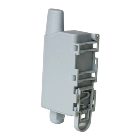
SOFTLINK Sigfox WS868-PLE-I User manual

Contents
1 Introduction 1
1.1 Sigfox communication network ....................................... 1
1.2 Module usage ................................................. 1
1.3 Hardware features .............................................. 1
2 Technical parameters overview 2
3 Configuration of the WS868-PLE-I module 3
3.1 Configuration of the module with using of the configuration cable .................... 3
3.1.1 Connecting of WS868-PLE-I module to computer ......................... 3
3.1.2 Using of ”PuTTy” freeware program for configuration ...................... 4
3.1.3 General rules for configuration of the module by configuration cable .............. 5
3.2 ”Configuration of the module with using of optical converter” ...................... 5
3.2.1 Installation of the ”WACO OptoConf” program .......................... 5
3.2.2 Connection of ”USB-IRDA” optical converter to computer .................... 6
3.2.3 Using of ”WACO OptoConf” program for configuration of modules ............... 6
3.2.4 General rules for configuration of the module by optical converter ............... 8
3.3 USB-CMOS converter driver installation .................................. 9
3.4 ”USB GateWay” and ”USB-IRDA” driver installation .......................... 10
3.4.1 How to disable driver signature enforcement in Windows 8 system ............... 11
3.4.2 How to disable driver signature enforcement in Windows 10 system ............... 11
3.4.3 Support of older OS Windows versions and OS Linux support .................. 12
3.5 Setting of WS868-PLE-I module parameters by configuration cable ................... 13
3.5.1 List of WS868-PLE-I module configuration parameters and commands ............. 13
3.5.2 Commands for saving of configuration parameters and reset ................... 13
3.5.3 Commands for setting of timers ................................... 14
3.5.4 Commands for setting of input counters .............................. 15
3.5.5 Commands for module activation and diagnostics ......................... 16
3.5.6 Module current status statement .................................. 16
3.6 Setting of parameters by using of optical ”USB-IRDA” converter .................... 18
3.6.1 Overview of module configuration parameters ........................... 20
3.7 Structure of module data messages ..................................... 20
4 Operational conditions 21
4.1 General Operation Risks ........................................... 21
4.1.1 Risk of mechanical and/or electric damage ............................. 21
4.1.2 Risk of premature battery discharge ................................ 21
4.2 The condition of modules on delivery .................................... 21
4.3 Modules storage ............................................... 21
4.4 Safety precautions .............................................. 21
4.5 Environmental protection and recycling .................................. 21
4.6 WS868-PLE-I module installation ...................................... 22
4.7 Module replacement ............................................. 23
4.8 Module dismantle ............................................... 23
4.9 Functional check of the module ....................................... 23
4.10 Operation of the WS868-PLE-I module .................................. 24
5 Troubleshooting 24
5.1 Possible causes of module failures ...................................... 24
5.1.1 Power supplying failures ....................................... 24
5.1.2 System failures ............................................ 24
5.1.3 Reading system failures ....................................... 24
5.1.4 Transmitter and receiver failures .................................. 25
5.2 Troubleshooting procedure .......................................... 25
6 Additional information 26
WS868-PLE-I i

List of Tables
1 Overview of WS868-PLE-I module technical parameters ......................... 2
2 Overview of WS868-PLE-I module configuration parameters ....................... 20
List of Figures
1 View of the WS868-PLE-I module ..................................... 2
2 Appearance of the USB-CMOS converter in Windows ”Device Manager” ................ 3
3 Configuration via USB port of computer .................................. 4
4 Terminal setting for serial line communication ............................... 4
5 Open terminal window for module configuration via serial line ...................... 5
6 Configuration of the module with using of optical converter ....................... 6
7 Displaying of the optical converter in the Windows’ ”Device Manager” ................. 7
8 Displaying of ”WACO OptoConf” configuration window” ........................ 7
9 List of variables in the working window of ”WACO OptoConf” program ................ 7
10 Example of module’s configuration table in the ”WACO OptoConf” window .............. 8
11 Attaching of optical converter to the holder ................................ 8
12 Appearance of converter without driver in the Windows ”Device Manager” table ........... 10
13 Displaying of the device without driver in ”Device Manager” window .................. 10
14 Manual selection of the driver file from a folder .............................. 10
15 USB driver installation ............................................ 11
16 The WS868-PLE-I module configuration table ............................... 18
17 Detailed view of WS868-PLE-I module ................................... 22
WS868-PLE-I ii

1 Introduction
This document describes features, parameters and setting possibilities of the WS868-PLE-I module, which is used
for reading of Elster BK-G series gas-meters and for radio-broadcasting of the data from the gas-meter to the
superior remote reading system in form of Sigfox standard messages.
1.1 Sigfox communication network
Sigfox communication network is a global radio frequency (RF) communication system intended for collecting
data from the huge number of terminal devices that transmit only a very limited amount of data. This kind of
network services are commonly referred as ”Internet of Things” (”IoT”).
Sigfox technology (including communication protocol) is optimizing for maximum radio range, that enables
building of country wide RF networks with a maximum cost effectivity. Unification of technology, global register of
identification addresses as well as central registration and control system enable interconnection of national networks
(”roaming”) into one global Sigfox network.
The module is designed for using in free 868 MHz frequency band with maximum transmitting power of 25
mW that is commonly used in European countries. Maximum reach of Sigfox services in this band for devices
with maximum transmitting power in open terrain is in range of tens of kilometers. This extensive range is enabled
by using of ultra-low modulation frequency (Ultra Narrow Band Modulation) where communication sub-channel
bandwidth is just 100 - 600 bps (Baud). As the messages are transmitted with such extremely low speed, Sigfox
message was invented as short as possible with maximum length of 26 Byte (maximum data content of 12 Byte).
Optimized length of message has positive influence on the terminal device energy consumption during transmitting
and receiving.
Sigfox network supports also bi-directional communication, if ”Downlink” service for transfer of data in reverse
direction is allowed, in earmarked time interval the Sigfox base station can deliver to terminal device a special
downlink radio-message containing configuration commands.
National Sigfox RF network consists of number of base stations, that are connected by data channels into one central
node (”star” type topology). The messages from Sigfox RF network are transferred from Sigfox central network
server to the application servers of authorized users through the unified data interface via public Internet.
1.2 Module usage
The WS868-PLE-I module can be used for remote reading of Elster BK-G series residential gas-meters that are
equipped with special slot (”lock”) for external remote reading modules (e.g. IN-Z61) in the lower side of its
counter. The module is equipped with one magnetic sensor for registration of gas-meter counter revolution and
one magnetic sensor for detection of detachment from gas-meter (”Tamper”). The module continuously registers
revolving of gas-meter pivotal wheel into its internal counter and broadcasts info-messages with current status of
gas-meter counter in form of Sigfox standard radio-messages (hereinafter ”INFO-message”). The INFO-messages
contain also service information about tamper status, battery voltage and processor temperature.
The INFO-messages are transferred through the Sigfox network to the central network server (”Back-End”), from
which there are forwarded to assigned IP-address of their addressee through the Internet. The addressee of the
messages is an application server of remote reading service operator, where the messages are decoded and processed.
The WS868-PLE-I module supports bi-directional communication that can be used for remote setting of counter
initial value and for change of broadcasting period. Required remote configuration values are delivered to the module
by special radio-messages of ”Downlink” service, that are assembled by ”Back-End” server on the application server
request and broadcasted by responsible base station.
1.3 Hardware features
The module is enclosed in plastic casing designed for mounting directly to the BK-G series gas-meter counter slot
reserved for remote reading modules. The device is not suitable for using in exteriors without additional protection.
The module is power supplied by internal battery with up to 10 years lifetime for frequency of 4 - 6 broadcastings
per day. Battery lifetime can be negatively influenced by shorter broadcasting period, or by storing and operation
in sites with the temperatures exceeding the recommended range. The module can be controlled and configured
either by configuration cable, or wirelessly - by infra-red remote control with using of optical converter.
External appearance of the WS868-PLE-I module is shown in the figure 1. Position of infrared sensor for wireless
configuration is marked by green arrow.
WS868-PLE-I 1

Figure 1: View of the WS868-PLE-I module
2 Technical parameters overview
Overview of WS868-PLE-I module technical parameters is shown in the Table1below.
Table 1: Overview of WS868-PLE-I module technical parameters
RF subsystem parameters
Frequency band 868,0 - 868,6 MHz
Modulation DBPSK
Sub-channel bandwidth 100 Hz
Transmitting power 15 mW
Receiver sensitivity 120 dBm
Communication protocol Sigfox
Transmission speed 100 Baud
Antenna intergrated
Configuration interface RS232
Transmission speed 4800 Baud
Operation mode asynchronous
Transmission parameters 8 data bits, 1 stop bit, none parity
Signal level TTL/CMOS
Optical configuration interface
Transmission speed 115 200 Baud
Optical interface specification IrPHY 1.4 standard
Inputs
Magnetic sensor of pivotal wheel revolving index ”0”
Mechanic ”tamper” sensor index ”1”
Power supplying
Lithium battery voltage 3,6 V
Lithium battery capacity 3,6 Ah
Weight and dimensions
Length (w/o sealing protrusion) 90 mm
Width (w/o ) 67 mm
Height 32 mm
Weight cca 120 g
Storage and installation conditions
Installation environment (by ˇ
CSN 33 2000-3) normal AA6, AB4, A4
Operation temperature range (-20 ÷40) ◦C
Storage temperature range (0 ÷40) ◦C
Relative humidity * 95 % (w/o condensation)
Degree of protection * IP20
WS868-PLE-I 2

3 Configuration of the WS868-PLE-I module
Configuration parameters of the WS868-PLE-I module can be displayed and changed from the common computer
(PC) by one of these methods:
- with using of ”USB-CMOS” converter and configuration cable connected to the module
- wireless, with using of ”USB-IRDA” converter
Technique of interconnection of the module with configuration computer and general rules of configuration are
described in detail in the section 3.1 ”Configuration of the module with using of the configuration cable”. The
description and meaning of all configuration parameters that can be checked and changed by cable can be found in
the section 3.5 ”Setting of WS868-PLE-I parameters via configuration cable”.
Description of interconnection of the ”USB-IRDA” converter with PC and general rules of configuration with using
of this optical converter are described in the section 3.2 ”Configuration of the WS868-PLE-I module with using
of optical converter”. The description and meaning of the parameters that can be changed by optical converter can
be found in the section 3.6 ”Setting of parameters by using of optical ”IRDA” converter”.
3.1 Configuration of the module with using of the configuration cable
Configuration of the module can be performed by using of any PC with MS Windows or Linux operating systems
interconnected by configuration data cable. The module’s communication interface is of RS-232 (COM) type with
CMOS signal level. The ”CONFIG CMOS” configuration connector is placed on the module’s printed circuit board.
3.1.1 Connecting of WS868-PLE-I module to computer
Configuration can be performed by using of common USB port of the computer. For the interconnection with
a USB port of computer it is necessary to use a manufacturer’s original configuration cable with ”USB-CMOS”
converter (see Figure 3). This converter creates a virtual serial port through the USB interface and adapts voltage
levels of the module’s configuration port to the standard USB port of common PC. So as to be able to create a
virtual serial connection via USB interface, there must be a relevant driver installed in the computer operation
system. After the ”USB-CMOS” converter is connected to computer for the first time, operating system will find
and install appropriate generic driver of ”USB Serial Device” category automatically. After driver installation is
completed, the device will appear in the ”Ports (COM and LPT)” section of the ”Device Manger” window as ”USB
Serial Device (COMx)” (see figure 2).
Figure 2: Appearance of the USB-CMOS converter in Windows ”Device Manager”
As some of the older MS Windows versions do not support a generic driver for USB serial ports, the automatic
installation of the driver could fail (system reports ”Driver software installation failure”, or ”driver not found“).
In this case there is necessary to install the driver manually, following the steps in paragraph 3.3 ”Installation of
USB-CMOS converter driver”.
Insert USB-CMOS converter to the USB port of computer. Open module’s casing to enable access to the configu-
ration connector. Connect configuration cable to the ”CONFIG CMOS” port on the WS868-PLE-I module printed
circuit board as depicted in the figure 3”Configuration via USB port of computer”. Thus the computer is connected
with the module and ready for performing any changes in configuration.
WS868-PLE-I 3

Figure 3: Configuration via USB port of computer
3.1.2 Using of ”PuTTy” freeware program for configuration
The module configuration can be done with using of any suitable program for the serial line communication. The
description bellow is relevant for the open-source software ”PuTTY“ that is available for free on www.putty.org.
Figure 4: Terminal setting for serial line communication
”PuTTY” software runs after clicking on the downloaded file ”putty.exe“. There will open a window of the terminal
communication (see Figure 4). For switching the program into the serial line communication, choose ”Serial” option
of the connection type in the ”Session” tab.
Check (or set up) the communication speed (”Speed”) to 4800 bits/s and then enter into the ”Serial line“ tab the
number of the serial port that the system automatically assigned to the virtual port at the moment of interconnection
WS868-PLE-I 4

module to the computer. The number of the serial port can be found in OS Windows by using of ”Device Manager”
(Control Panel/System and Maintenance/Device manager) by clicking on ”Ports (COM a LPT)” where the numbers
of ports appear (e.g. ”COM23” - see figure 2).
Click on ”Open” button in ”PuTTY” program and open the terminal window. After pressing of ”ENTER” key
there will appear a command prompt ”sig50” which announces that the module is ready to be configured (see
figure 5).
Figure 5: Open terminal window for module configuration via serial line
3.1.3 General rules for configuration of the module by configuration cable
Activate the terminal window for the configuration via the configuration cable according to the instructions above.
These general rules are valid for entering commands in the command line:
•the command must be entered only when a prompt for command appears in front of the cursor mark (colored
or flashing little square); the prompt is either ”sig50” or ”mon” format (see figure 5);
•it is possible to enter only one command each time;
•the command could be entered in an alphanumeric character (or several characters);
•the command is sent to device by clicking on ”ENTER” key. After the command being carried out, the
prompt will appear again and it is ready for a new command to be entered. In case the command fails to
execute, there will appear an error report;
•check the execution of the command by displaying of the list of configuration parameters which appears by
entering ”show” or ”/” and pressing on ”ENTER” key;
•to display a summary of configuration commands and their parameters (”HELP”), enter ”?” (question mark),
or ”/?” and press ”ENTER” key;
•when entering characters, distinguish strictly the capital and small letters (according to the documentation
or ”HELP”);
•Do not enter other characters than those listed in ”HELP“ or in the documentation, otherwise you would
be risking the unwanted command enter that might be the same as the ones used for manufacturer settings,
diagnostics or service and repair.
3.2 ”Configuration of the module with using of optical converter”
The module is equipped with an InfraRed interface that is intended for configuration with using of ”USB-IRDA”
converter. This converter serves for wireless transfer of configuration data (commands and values) between module
and configuration computer via modulated beam of light in infrared band. By using of this kind of configuration there
is possible to make all common settings through the transparent casing without necessity to open the module’s cover
(see figure 6). Optical beam goes through the transparent casing and it is decoded by the infrared modem placed
on the module’s printed board (PCB). A special software application program ”WACO OptoConf” written in
Java language can be used for required settings. This program can be installed to the computers with MS Windows
as well as Linux operating systems.
3.2.1 Installation of the ”WACO OptoConf” program
Installation of the ”WACO OptoConf” program can be performed from the ”Optoconf.zip” installation pack.
Copy the pack to any folder of the computer and unpack it by any ”unzip” program. The installation pack contains
following files:
-”optoconf.jar” - executable file of the program
-”lib” - folder with ”library” files
-”README.TXT” - ”readme” file
-”SetupJSerial.msi” - serial port support for Java (installer)
-”ugw3.inf” - driver for USB-IRDA converter
WS868-PLE-I 5

Figure 6: Configuration of the module with using of optical converter
The ”WACO OptoConf” program can be started each time by launching of ”optoconf.jar” file (clicking on the file
name or to the created desktop shortcut to this file).
Check whether the ”Java Runtime Environment” (Java Virtual Machine) program in the 8 or higher version is pre-
installed in the computer. If after launching of the ”optoconf.jar” file a Java-window of the configuration program
does not open (or pop-up window ”How do you want to open this file?” appears) then the Java support it is not
installed (or installed in older version) and it is necessary to perform its installation (32-bit version for Windows,
64-bit version for Linux). The Java Runtime Environment program is available on the official Oracle WEB site for
Java support here: Download Free Java Software
After installation of the Java Runtime Environment install the driver for a serial interface support in Java envi-
ronment by clicking to ”SetupJSerial.msi” file. The installer of driver starts running. The installation is very
simple - it only requires confirmation of necessary changes in computer configuration (”Do you want to allow this
app to make changes to your PC?”). After the driver is installed try to start ”WACO OptoConf” program again
and if everything is all right the program window will be opened. Close the program window.
3.2.2 Connection of ”USB-IRDA” optical converter to computer
Before starting of the ”WACO OptoConf” program connect the ”USB-IRDA” converter to USB port of the
computer. When the converter is connected to computer for the first time an operating system will automatically
find and install correct driver for the converter (i.e. generic driver for ”USB Serial Device” category of device).
After driver is successfully installed to MS Windows computer, the device should appear in the ”Device Manager”
in section ”Ports (COM and LPT)” as ”USB Serial Device (COMx)” (see figure 7).
Older versions of MS Windows do not support generic driver for support of serial ports via USB. I this case install
the ”ugw3.inf” driver from delivered installation pack according to the instructions mentioned in the paragraph 3.4
”USB GateWay” and ”USB-IRDA” driver installation” below.
3.2.3 Using of ”WACO OptoConf” program for configuration of modules
Start the ”WACO OptoConf” program by clicking on the ”optoconf.jar” file name or to the pre-created desktop
shortcut to this file. Program window ”WACO configuration” will open (see figure 8). In Config/Port item of
menu choose name of serial port assigned to USB-IRDA converter by operating system (see figure 7). The program
is thus fully functional and ready for configuring parameters. Menu item ”Config/Look and Feel” serves only
for choice of window color and design by clicking to one of pre-configured options.
By clicking to ”Walk device” button the list of all variables that are used for module configuration can be displayed
(see figure 9.
WS868-PLE-I 6

Figure 7: Displaying of the optical converter in the Windows’ ”Device Manager”
Figure 8: Displaying of ”WACO OptoConf” configuration window”
Figure 9: List of variables in the working window of ”WACO OptoConf” program
Index and description of all variables of the NEP protocol, that is used for coding of data in Softlink’s ”wacoSystem”
communication systems can be found on the producer’s WEB site NEP Page.
By clicking to ”Read device” button the textbfconfiguration table with all the relevant parameters of the module
is displayed in the working window. Non-configurable (read only) parameters are displayed as ”inactive” (with gray
editing fields), while parameters that can be changed by ”WACO OptoConf” program are displayed inside white
editing fields (”active fields”). Example of configuration table of the module is depicted in the figure 10.
WS868-PLE-I 7

Figure 10: Example of module’s configuration table in the ”WACO OptoConf” window
3.2.4 General rules for configuration of the module by optical converter
Connect USB-IRDA optical converter to the USB port of the computer. Flashing of green LED signalizes correct
function of the converter. By clicking to ”optoconf.jar” file (or its shortcut) launch ”WACO OptoConf” program.
If not chosen automatically by previous functioning, choose the name of serial port of the converter (”COM XY”)
in the ”Config/port” menu.
Configuration can be performed either on the working desk or with using of a special holder for attaching of optical
converter to the module.
Configuration on the working desk means that computer as well as the module are placed on the any convenient
work surface (e.g. on the desk - see figure 6). In this case the module should be placed not more than 15 cm from the
tip of converter, the module’s printed board must be facing to converter by its element side, and module’s optical
sensor should be lying approximately in the converter’s axis of symmetry (i.e. in the direction of the infrared beam).
Approximate position of the optical sensor of the module is marked in the figure 1by green arrow. Correctness of
mutual position module/converter can be checked by displaying of the current configuration as described below. It
is necessary to fix and keep such position in which the communication between module and converter is reliable.
When working directly at the installation site always use a special holder that is designed for attaching of converter
to the module. Put the holder to the WS868-PLE-I module as shown in the figure 11.
Figure 11: Attaching of optical converter to the holder
Put holder to the module from the element side and shift it to that side where the optical sensor is placed (approx-
imate position of the optical sensor is marked in the figure 1by green arrow). Connect the converter with laptop
by using of extension USB cable and insert the converter to the slot in the holder as shown in the picture. Check
correctness of converter’s position by displaying of the current configuration as described below. If the connection
is not reliable shift the holder along the module’s cover. The best position is if the converter is right opposite to
sensor.
By clicking to ”Read device” open a configuration table with all the relevant parameters of the module. Parameters
that can be changed are displayed in white colored editing fields. There are four types of editing fields:
- text fields, in which a text can be edited (e.g. ”Info-text” field)
- numeric fields, in which a change of number can be done
- selection fields, in which a choice from pre-set options can be done
- hexadecimal fields (marked by ”hex”), in which hexadecimal characters can be entered
Text fields can be changed by correcting, erasing, or rewriting of the text inside the field.
Numeric fields can be changed by rewriting number inside the field or by its increasing/decreasing with using of
WS868-PLE-I 8

arrows ∆a∇.
Selection fields can be changed by clicking to symbol ∇and choosing required option from the list-box.
Hexadecimal number fields (e.g. ”8B 01”) can be changed by clicking on the character and rewriting its value
to another hexadecimal character (0 to F).
For editing of individual items keep following rules:
•after making any change in editing field there appears symbol ”√” before the field that is an indication of
active change request that will be sent to the module;
•by clicking to ”Write” button in the lower part of the configuration table the program sends configuration
commands through the USB-IRDA converter. During the process of establishing connection converter’s LED
light stops flashing for approximately 2 seconds and then lights-up;
•after sending data to module the program automatically requests a new status of configuration. Displaying of
the new current status of configuration parameters (after requested changes) is signalized by disappearance
of symbol ”√”before editing field;
•if requested change of some parameter is out of its range, the change is not accomplished and after disappear-
ance of symbol ”√”there appears an original value in the editing field;
•the program enables making multiple configuration changes at one time. If there are changes in several editing
fields of the table, each of them is marked by symbol ”√” and after clicking to ”Write” button all the changes
are requested/performed;
•if some of the fields was edited unintentionally (by mistake) and the change of this field is not really requested,
by clicking to symbol ”√” the field can be ”unchecked” and the change request of the parameter is not sent
to module;
•current status of all configuration parameters of the module can be requested anytime by clicking to ”Read”
button in lower part of the table;
•ongoing communication between module and USB-IRDA converter may be signaled by flashing of LED on
the configured device;
•if the connection between USB-IRDA and the module was not established until several seconds, error window
”Error: Read timeout” will appear in the program window;
•the most common reason of connection failure is either bad position of the module (long distance, wrong
orientation, dirty cover, obstacle in the beam), or the module’s battery was switched off.
NOTE! ”WACO OptoConf” program contains specific data and settings for interworking with certain types of
modules. Each version of the program thus supports only the relevant versions of the wacoSystem modules (i.e.
actual versions of the modules up to date of the software release). If after reading of data from the module the error
window ”Error: Unknown device” will appear, the current version of the program does not support configuration
of this version of the module. In this case it is necessary to download a new version of the ”WACO OptoConf”
program from the product WEB site www.wacosystem.com/podpora, or contact manufacturer’s technical support
3.3 USB-CMOS converter driver installation
If the computer operation system failed in automatic installing of the driver for the ”USB-CMOS”, it is necessary
to install the driver manually. The relevant current driver can be found on a chip manufacturer’s (FTDI) webpages,
namely in the ”VCP Drivers“ (Virtual COM Ports) section.
www.ftdichip.com/Drivers/VCP.htm
In the ”Currently Supported VCP Drivers” table find a link to a driver relevant to your operating system. To
download the file, click on a link in the table. After downloading the file (in .ZIP format) into any directory in
your computer, unzip the file. It will create a new folder (directory) with a set of files (e.g. ”CDM 2.08.24 WHQL
Certified”).
Connect the converter ”USB-CMOS“ to your computer and open a ”Device Manager” tool. The converter with the
disabled driver will be displayed in the top right corner of the window as ”Other Devices” (see figure 13 left).
Click by right mouse button on ”USB Serial Port” and choose ”Update Driver Software” option in the context menu.
Choose ”Find Driver in this computer” option in the ”Update Driver Software” window. Use ”Browse” button to
set up the path to the driver‘s folder (directory) and then click on the ”Next” button. The driver installation process
will launch. After the driver installation is completed, the standard ”Installation Completed” message will appear.
After the installation the converter will appear in the ”Ports (COM and LPT)” section of the ”Device Manager”
window (see figure 13 right).
WS868-PLE-I 9

Figure 12: Appearance of converter without driver in the Windows ”Device Manager” table
3.4 ”USB GateWay” and ”USB-IRDA” driver installation
The driver ”ugw3.inf” intended for support of multiple virtual serial ports through the USB interface of a computer
is a part of delivered installation pack. If your version of MS Windows operating system failed in automatic
installation of a driver for connected ”USB GateWay” or ”USB-IRDA” device, make an installation of ”ugw3.inf”
driver manually.
Connect the device to computer and open a window of ”Device Manager” tool. The device appears in the ”Other
device” section in upper part of the window as ”USB Serial port” device (see figure 13 left).
Figure 13: Displaying of the device without driver in ”Device Manager” window
By right-clicking to ”USB Serial port” open the context menu and choose ”Update driver software” item. Click on
”Find driver in this computer” in the opened window. Click to ”Select driver from the list” and ”Next” in next
window. After a new ”Select device type from the following list” window appears, select ”Ports (CPM & LPT)” in
the window and click to ”Next” button (see figure 14 left). Choose ”From disc” in the next ”Choose driver which
you want to install” window ( figure 14 right).
Figure 14: Manual selection of the driver file from a folder
After that a new ”Find file” window appears. Set the folder with driver file in the ”Browse” tool, select ”ugw3.inf”
file name that will appear in the window and click to ”Open” button (see figure 15 left). A new ”Choose driver
WS868-PLE-I 10

to be installed for the hardware” window will appear, select ”RFU Gateway Serial port” item and click to ”Next”
button (see figure 15 right).
Figure 15: USB driver installation
A new ”Driver software installation” window will appear with standard red ”unknown driver producer” Windows
system warning. Click to ”Install the software anyway” option and the installation process will launch (*). After
the process is completed the system shows positive message ”The driver was successfully installed” (or similar).
The device will move to the ”Ports (COM & LPT)” section of the ”Device Manager” window (see figure 13 right).
(*) If installing the driver into the Windows 8 or Windows 10 OS computer, it could be a security problem with
the installation because the driver doesn’t have a digital signature (”unsigned driver“). In this case follow the
instructions below.
3.4.1 How to disable driver signature enforcement in Windows 8 system
Enforcement of signed driver installation in Windows 8 can be disabled by following procedure:
•by pressing the ”Windows + R” keys open the ”Run” window;
•write a restart command ”shutdown.exe /r /o /f /t 00” into the ”Open” editable field;
•choose ”Troubleshoot” option in the ”Choose an option” window that will pop-up;
•choose ”Advanced options” in opened ”Troubleshoot” window;
•choose ”Windows Startup Settings” in opened ”Advanced options” window and run ”Restart”;
•during the system restart process a window ”Advanced Boot Options” appears, choose ”Disable Driver Sig-
nature Enforcement” option in this window;
•after launching the system install the driver according the above mentioned instructions.
Deactivation of the enforcement of signed driver function of the Windows 8 operating system is functional only
until the next restart of the system.
3.4.2 How to disable driver signature enforcement in Windows 10 system
Enforcement of signed driver installation in Windows 10 can be switched-off by following procedure:
•click to ”Windows” icon in left the bottom left corner of the screen and choose ”Settings” icon;
•select ”Update and security” in ”Settings” window;
•select ”Recovery” in next window’;
•select ”Advanced startup” section in ”Recovery” window and click to ”Restart” button in the section;
•in a few seconds the new ”Choose an option” screen appears; select ”Troubleshoot” option;
•in next steps select ”Advanced options” and ”Startup repair” options and click to ”Restart” button;
•in this step an instruction for entering of ”BitLocker” recovery key could appear (depends on the system
settings). This is a 64-character access key for data section of the user that can be used in case of loss of OS
Windows password. The key can be found in the ”Microsoft Account Settings” page, that can be displayed by
clicking to ”Windows” icon and ”User” item of main Windows menu. To get to the account it is necessary to
click to ”Change account setting” and ”Manage my Microsoft account” and log into the account by using of
Microsoft user login/password. Select ”Device” in main menu of the user account page and click to ”Obtain
WS868-PLE-I 11

BitLocker recovery key” in ”Desktop” section and ”Bitlocker” subsection. The new screen with recovery keys
will open. Copy down the key that is valid for the required unit (according to the required unit identifier);
•after entering of the key the new screen with startup options will appear, select ”Disable Driver Signature
Enforcement” option from the list. The selection can be done with using of F1 - F10 keys, for selected option
with order number ”7” press key ”F7”;
•after OS Windows restart perform the driver installation according to the above described procedure.
Deactivation of the enforcement of signed driver function of the Windows 10 operating system is functional only
until the next restart of the system.
3.4.3 Support of older OS Windows versions and OS Linux support
Earlier MS Windows versions (Vista, Windows XP and older ones) do not support sufficiently the installation of
multiple virtual serial ports onto one physical USB port and the current versions of ”USB GateWay” and ”USB-
IRDA” devices cannot be connected to the computers with these operating systems.
There is no need to install any drivers with serial port support to the computer with Linux OS as the Linux system
will automatically use its own generic drivers.
WS868-PLE-I 12

3.5 Setting of WS868-PLE-I module parameters by configuration cable
In following part of the document there is a description of these parameters of the WS868-PLE-I module, that can
be displayed and examined from PC connected to the module by configuration cable. Some of the parameters can
be changed by configuration commands entered ”from the console” as described in paragraph 3.1.
3.5.1 List of WS868-PLE-I module configuration parameters and commands
List of all configuration parameters of the module can be displayed by entering of ”/“ command and pressing of
”ENTER” key. The following list of parameters will display in the terminal window:
sig50>/
CONFIGURATION: OK
Mode Setup: 1
XTAL ppm: -21
sending time: 3600
measure time: 300
downlink : 0
i[0] 0 0 1 1 0
i[1] 0 0 1 1 0
Debug level: 0
sig50>
List of all configuration commands (”HELP”) can be displayed by entering of ”/?” command into the command
line and pressing of ”ENTER” key. The following list of commands will display in the terminal window:
sig50>/?
/W - write configuration
/# - erase configuration
/x - RESET
/M - enable mode setup on startup
/! ppm - set Xtal ppm
/s sec. - set sending time in seconds
/m sec. - set measure time in seconds
/d n - n-th uplink message has downlink capability, 0 - no downlink
/i index value - set initial value
index t number- set type
index e 0|1 - set edge
index m value - set multiplier
index d value - set divisor
/D number - debug level
sig50>
Overview of configuration parameters with short description of their meaning can be also found in table 2on the
page 20.
The meaning of individual parameters and detailed description of their usage can be found in the following part of
chapter 3.5.
3.5.2 Commands for saving of configuration parameters and reset
The module contains two sets of configurations: operating configuration and saved configuration. At the start of
the system the module copies saved configuration into the operating configuration, with which continues to work.
If user changes configuration parameters, it does so only in operating configuration.
Current status of storing of configuration parameters can be displayed in the list of all configuration parameters as
”CONFIGURATION” item:
CONFIGURATION: OK
Information ”OK” means, that the operating configuration is stored (it is identical with stored configuration)
WS868-PLE-I 13

Information ”NOT WRITTEN” means, that the operating configuration is different from the configuration stored
in Flash.
Configuration can be saved to Flash memory by using of ”/W” command. Example:
sig50>/W
If the current operating configuration was not stored to FLASH memory, the module returns to the saved config-
uration after reset. If the parameter should be changed only temporarily (for example switch-on ”test” function
during diagnostics), it is not necessary to save operating configuration into FLASH memory (after diagnostics the
function will be switched-off anyway). If the parameter should be changed permanently, there is necessary to save
the configuration to FLASH memory.
Configuration can be erased from the Flash memory by using of ”/#” command. Example:
sig50>#
WARNING! This command is recommended to use only by users with good knowledge of the system, or after
consultation with the manufacturer.
The module reset can be performed by using of ”/x” command. Example:
sig50>/x
After entering the command, the module goes to software restart.
3.5.3 Commands for setting of timers
This group of commands enables setting of measurement and broadcasting intervals and setting of receiving (”down-
link”) mode. There are following commands:
/s sec spontaneous messages broadcasting period (sec)
/m sec A/D converter measurement interval (sec)
/d number setting of frequency of ”downlink” activation
The ”/s sec” command can be used for setting of the module broadcasting period. The period is set in seconds
and the module broadcasts its INFO-messages spontaneously with this period. Example of setting of broadcasting
period to 1 hour (3600 seconds) and corresponding record in the module configuration summary:
sig50>/s 3600
...
sending time : 3600
WARNING!. Frequency of broadcasting in Sigfox network is under regulation. Each device working in Sigfox
network has assigned its service profile that enables only limited number of broadcasted messages per day. Exceeding
this limit can cause some restriction or sanction from the Sigfox service provider. When setting this parameter,
check whether the setting complies with a service contract, that is valid for configured device.
The ”/m sec” command can be used for setting of the time interval for measurement of some operational pa-
rameters (temperature, voltage...). As the latest values of measured quantities are broadcasted in INFO-messages,
measurement interval should be always shorter than broadcasting period. Example of setting of measurement inter-
val of analogue quantities to 5 minutes (300 seconds) value and corresponding record in the module configuration
summary:
sig50>/m 300
...
measure time : 300
By using of ”/d number” command a frequency of activation of receiving (”Downlink”) channel can be set. The
number ”n” in this command determines frequency of receiving channel activation according to this principle:
- if ”0” value is set, receiving channel is closed (”Downlink” service disabled)
- if ”1” value is set, receiving channel is opened after each INFO-message
- if ”2” value is set, receiving channel is opened after every second INFO-message
WS868-PLE-I 14

- if ”n” value is set, receiving channel is opened after each n-th INFO-message
Example of setting of receiving channel activation frequency to such mode, when the receiving channel opens after
every fourth broadcasted message, and corresponding record in the module configuration summary:
sig50>/d 4
downlink: 4
Example: If the module broadcasts INFO messages eight times per day (sending time = 10800 second) and downlink
channel will be opened after each fourth transmission, the module will be able to receiive dowlink message two times
per day.
WARNING!. ”Downlink” service of the Sigfox network is under regulation. This service is allowed only for some
Sigfox service profiles and with limited frequency. When setting this parameter, check whether the setting complies
with a service contract, that is valid for configured device.
3.5.4 Commands for setting of input counters
The WS868-PLE-I module is equipped with two input pulse counters (index 0 - 1) optimized for working with
specific series of gas-meters. The first sensor input is adapted for registration of gas-meter revolving, second input
serves for for registration of tamper status (detection of module disconnection from the gas-meter). Each input
counter can be set individually with using of following commands:
/i index value setting of initial value of the counter
/i index t number setting of counter mode (not applicable)
/i index e 0/1 setting of trigger edge (not applicable)
/i index m value setting of multiplier (output value = counter value * multiplier)
/i index d value setting of divisor (output value = counter value / divisor)
Important note:
The first input (with index ”0”), that registers revolving of gas-meter pivotal wheel, has factory preset counter
mode and trigger edge parameters. Setting of these parameters has no relevance for this module and it is recom-
mended not to use respective commands for their setting.
The second input (with index ”1”), that registers module disconnection from gas-meter, has factory preset
all counter parameters. Setting of these parameters has no efect for the module and it is recommended not to use
respective commands for their setting.
By using of the ”/i index value” command setting of the initial value of the input counter can be performed.
Initial value of the input should be entered as a natural number.
Example of setting of the first input (port ”0”) to the initial value ”124”:
sig50>/i0 124
sig50>
The ”/i index m value” and ”/i index d value” commands can be used for setting of multiplier and divisor
constants for adjusting of output values to required output units. Default setting of both values is ”1”. If it is
necessary to adjust the counter value by some coefficient, enter convenient combination of multiplier and divisor as
shown in example below.
Multiplier setting example:
Gas-meter generates measuring pulses after each 0,01 m3. To indicate gas consumption in 10−3m3(litres), it is
necessary to multiply counter value by ”10”.
Setting of multiplier to ”10” value can be performed as follows:
sig50>/i0 m 10
sig50>
Setting of counter initial value to ”124” and multiplier value to ”10” will display in the module configuration status
as follows:
WS868-PLE-I 15

i[0] 0 0 10 1 124
i[1] 0 0 1 1 0
Parameters of each input counter are displayed in one row of the statement in following order: mode - edge -
multiplier - divisor - current value.
It is clear from the statement that current value of ”0” input (124) will be presented in broadcast message as 1240
(litres).
Divisor setting example:
Gas-meter generates measuring pulses after each 0,1 m3. To indicate gas consumption in m3, it is necessary to
divide counter value by ”10”.
Setting of divisor to ”10” value can be performed as follows:
sig50>/i0 d 10
sig50>
Setting of counter initial value to ”124” and divisor value to ”10” will display in the module configuration status as
follows:
i[0] 0 0 1 10 124
i[1] 0 0 1 1 0
It is clear from the statement, that current value of ”0” input (124) will be presented in broadcast message as 12
(m3.).
3.5.5 Commands for module activation and diagnostics
This group of commands is intended for the module initial setting during the manufacturing process, and for module
diagnostics by manufacturer. These commands are only for manufacturer use.
There are following commands:
/M switching to module initialization mode ”Mode setup” ((Do not use! Only for
factory setting!)
/! ppm enteering of ”XTAL” correction constant ((Do not use! Only for factory setting!)
/D number ”debug” statement switch-on (Do not use! Only for factory setting!)
WARNING It is strongly recommended not to use these command during normal operation. Using of these
commands can cause device malfunction!
The ”T” command (without ”slash”) can be used for immediate transmitting of standard INFO-message (out
of scheduled time). This command can be used for example for checking of radio connection during the module
installation. When using this command, it is necessary to realize that each device working in Sigfox network has
assigned its service profile that enables only limited number of broadcasted messages per day. Exceeding this limit
can cause some restriction or sanction from the Sigfox service provider.
3.5.6 Module current status statement
Themodule current status statement can be displayed by entering of ”i” command (without ”slash”) into the
command line and pressing of ”ENTER” key. Following statement will appear in the terminal window:
sig50>i
SIG50 HW 1.50 SW: 1.0
0:54:29 1.1.1900 Reset cause=0 (0004) Uptime=476
ID: 0018C48A
PAC: 853F16CCDC2FB9D7
temperature[1]: -500.0
temperature[2]: +32.3
humidity[1]: -1
voltage[1]: 3467
sig50>
WS868-PLE-I 16

In the first row there are displayed following device specifications: manufacturer type (Device name), hardware
version/revision (HW version.revision) and software version/revision (SW vesion.revision). These specifica-
tions are factory set and cannot be changed.
In the second row there are values of module system time in common time format, reset cause of module
last reset and value of module ”Uptime”.
The ”Systime” parameter value shows setting of module real time. System time is kept in the same format as
in computer operating systems, i.e. in seconds, starting from 1.1.1970 (”UNIX Epoch time”). In default status
(after battery switch-on) there is zero value in the counter and it increases by one every second. As setting of this
parameter is not required for any common application of the module, command for its setting is not included in
the set of configuration commands.
The ”Uptime” parameter value shows the time interval passed from the last device reset in seconds so that the
exact moment of the last module reset can be recognized by this parameter. The parameter cannot be changed by
user (”read only” type).
The ”Reset cause” parameter value gives an information about the last reset circumstances. Following reset codes
are relevant for this type of device:
-”0” means ”Cold start” (caused by user ”RESET” command)
-”1” means ”Warm start” (based on ”suspension” cause
-”2” means ”Watchdog reset” (reset by ”watchdog“ system)
-”3” means ”Error reset” (incorrect instruction or inconsistent data)
-”4” means ”Power reset” (caused by low power voltage)
The parameter has ”read only” character and it is used mainly for the diagnostics.
In the third row there is a value of module Sigfox ID, that is an unique identifier of the device in the Sigfox
global network. This ID is permanently assigned to the given module and cannot be changed.
In the fourth row there is a value of module Sigfox ”PAC” code (Personal Authentication Code), that is an
unique identifier of assigning of the given device to concrete customer - service contractor. Initial PAC-code is
assigned to the module in factory and can be changed only with co-operation with Sigfox network provider (with
possible change of service contractor). Initial PAC-code is written in module configuration as an information for
user. Setting of this parameter has no influence on the module functionality. After possible change of service
contractor, the new contractor could decide to register change of PAC-code in the module configuration or not.
In next rows there are values of current temperature measured by sensor (temperature [1]), current processor
temperature (temperature [2]), current humidity measured by sensor (humidity[1]), and current voltage of
internal battery (voltage [1]). As the module is not equipped by temperature/humidity sensors, the ”temperature
[1]” and ”humidity[1]” values are random numbers with no practical meaning.
WS868-PLE-I 17
Table of contents
Popular Measuring Instrument manuals by other brands
Geotech
Geotech Interface Probe with Float Installation and operation manual

Agilent Technologies
Agilent Technologies 81200 installation guide

Berthold
Berthold Uni-Probe LB 491 user manual

Zircon
Zircon SuperScan M4 user manual

Omega
Omega Vortex FV100 Series user guide

SpiroClinic
SpiroClinic Pro user manual

