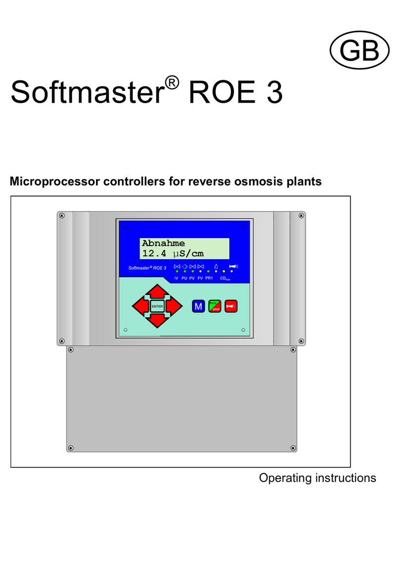
Softmaster ROE 3 User manual

Softmaster®ROE 3
Microprocessor controllers for reverse osmosis plants
Operating instructions

Table of contents
General notes ........................... 1
Introduction ................................ 1
Handlingnotes.............................. 1
Safetynotes................................ 1
Installation and commissioning ................. 1
General description ...................... 2
Viewsofdevice ............................. 2
Description of display and operating features ...... 3
Display functions ........................... 4
Display-topline ................................4
Display-bottomline .............................4
LEDdisplays...................................4
Statusdisplays .................................5
Error messages ............................ 6
Terminal block identification ............... 9
Functions ................................... 9
Description of relay outputs ................. 11
PU1/PU2, Pressure pumps 1 and 2 ................11
IV Input valve .................................11
FVFlushvalve ................................11
PVOutputvalve ...............................11
PR1Programmablefunctionoutput1...............13
PR2 Programmablefunctionoutput2 .............. 13
AL Fault message output ("Alarm") .................13
Impulse/Meteringoutput ......................... 13
Description of signal inputs ................. 14
MPMotorprotection ............................ 14
HL and LL High and low level .....................14
HPHighwaterpressure .........................15
LPLowwaterpressure ..........................15
STOPSwitching-offoftheplant ...................15
COConcentratemonitoring.......................16
PROG Programmable function input ................16
CD1/CD2 Connections for conductivity electrode ...... 17
PT100 Connection for temperature sensor PT100 ..... 17
Watertemperaturemonitoring.....................18
OUT Interface output ....................... 18
Functioning ............................ 19
Switching on and power failure ................... 19
Production ................................ 19
Standby .................................. 19
Flush after production ....................... 19
Intervalflush............................... 19
Quality flush and emergency service ............ 19
Conductivity monitoring ...................... 20
Programming ........................... 21
Startmenu .................................... 21
Menu selection ................................. 21
Input ......................................... 21
Endmenu ..................................... 21
Informationmenu ............................... 21
Enter/change password ........................... 22
Flushingmode.................................. 22
Flushingduration................................ 22
Intervalflush ................................... 22
Qualityflush ................................... 22
Probe Permeate ................................ 22
LVPermeateMax. .............................. 22
LVPermeateMin. ............................... 22
Probe CD2. .................................... 23
Temperature compensation ....................... 23
LVTemperature ................................ 23
FunctionPump ................................. 24
FunctionLowwaterpressure ...................... 24
FunctionExcesspressure......................... 24
FunctionConcentrate ............................ 24
FunctionMotorprotection ......................... 24
FunctionStop .................................. 25
FunctionPROG................................. 25
Watermeter ................................... 25
Metering ...................................... 25
Function PR1 input .............................. 25
FunctionPR2output ............................. 26
0/4-20mAOUT ................................. 26
Release....................................... 26
Language ..................................... 26
Service menu ........................... 27
Manual flush ................................... 27
Autom.flush ................................... 27
Errorhistory.................................... 27
Calibration of conductivity sensor CD ................ 28
Operating hours ................................ 29
Watermeter ................................... 29
Time/Date ..................................... 29
Diagnosis ..................................... 29
Softwarestatus ................................. 29
Menu structure overview .................. 30
Technical appendix ...................... 31
Exampleofanosmosisplantlayout ............. 31
Connection example ......................... 31
Technicaldata .............................. 32

1 / 32
General notes
Introduction
These operating instructions describe the installation, operation and programming of the reverse osmosis controller
Softmaster ROE 3.
We recommend that, whilst familiarising yourself with the operation of the unit aided by this manual, you have immediate
access to the operable controllerin order to perform the functionsand combinationsasdescribed. Ascertain functionsare
interrelated, it is advisable to follow the instructions in the given order.
Should problems or questions arise which are not described in this manual and/or cannot be solved, our customer service
is always at your disposal.
Try to identify the problem as accurately as possible and record the conditions under which it occurred. This will enable
us to offer you swift effective assistance.
Handling notes
Quick, repeated switching on/off of the controller should be avoided. Wait at least 5 seconds before switching the unit
either 'on' or 'off' at the main switch.
Only operate the controller in compliance with the ambient conditions (e.g. temperature, moisture) stated in the chapter
entitled technical data. Especially protect the controller against moisture.
The controller should not come into contact with splash or condensation water.
The original seals attached during manufacture (EPROM labels) must not be broken; otherwise all warranty claims will be
withdrawn.
Before dismantling a defect controller, always write down the description of the error (failure effect). Repair work
(independent of the guarantee period) is only possible after the unit has been dismantled and returned to us with a
description of the error.
The allowed maximum electrical load capacity of the relay outputs and the total power rating of the plant must not be
exceeded.
The controller should only be used for the stated intended purpose.
Safety notes
Always pay attention to the following safety notes:
The controller must be installed and operated in compliance with the relevant standards (e.g. DIN, VDE, UVV), or in
accordance with the regulations laid down by the individual country.
Some functions (e.g. manual production) allow direct manipulation of the plant (valves, pumps, etc.), without locking or
monitoring. These functions are thus protected by a password and are only to be used by trained personnel.
If you observe malfunctioning of the controller, switch it off immediately and inform the service personnel.
Do not attempt to repairthe controller yourself (loss of warranty rights); instead always get in touchwith authorized service
personnel. This is the only way a reliable and safe operation of the plant can be ensured.
After protective equipment (safety fuse, motor protection circuit breaker) has been triggered, attempt, at first, to eliminate
the cause of the malfunctioning (e.g. clean the pump) before reactivating the protective equipment. Frequent triggering is
always due to an error which, in certain circumstances, may also cause damage to the controller.
Ignoring these notes can result in damage to the controller as well as the plant and may result in a loss of warranty rights.
Installation and commissioning
Installation as well as commissioning must only be undertaken by authorized technicians!
The connecting cables to the sensors should be kept as short as possible and clear of power cables. Close proximity to
strong electromagnetic radiators can lead to deviations of the display; in this case, separate interference suppression
measures should be carried out.
After installation, program the unit with the plant-specific features and data (e.g. switch functions, conductivity limit values,
etc.). The data is permanently stored (also during power failure).

2 / 32
General description
Views of unit
Wall-mounted variant Panel-mounted variant
Terminal box Terminal box
Drilling scheme for wall-mounted variant Panel cut-out for panel-mounted variant

3 / 32
Description of display and operating features
A On/Off switch
Only the wall-mounted variant is equipped with a On/Off
switch. Use this switch to switch the unit on or off.
B Safety fuse, max, T6.3A
The safety fuse protects the outputs against overload or a
short circuit. (Inside the unit)
C Thermal fuse (optional)
Thermal fuse protection for the pump motor, max. 6.3 A.
D "ENTER" key
Confirm inputs and trigger functions with the ENTER key.
E Arrow keys
Use these keys to operate the menu drive in the display
and to enter values and programming data.
F "M" key
Call the menu and return from submenu levels.
G "Run/Stop" key (“Production/Standby”)
Manual triggering of production: Plant is put into operation
or manual triggering for STOP/ Standby: Plant goes into
the Standby position.
H "Fault OFF" key
Deletes the alarm signal at output 'AL' (Alarm); a fault
display can only be deleted if the fault has been
eliminated.
I LED functions
LED symbols always signal the status of the plant,
independent of the level (menu) being worked on.
J LC display
Two lines with 16 characters, backlit.

4 / 32
Display functions
Display - top line
The top line displays plant statuses and values (described below).
Display - bottom line
Alternate display of the conductivity for permeate (CD1) and sensor CD2 (see technical data for measuring ranges) and
the water temperature (2-digit, only with automatic temperature compensation).
LED displays
The LEDs display active plant components and occurring error messages.
IV (green)
LED lights up: Input valve is open.
PU (green)
LED lights up: Pump 1 and/or pump 2 is/are switched on.
PV (green)
LED lights up: Output/Permeate valve is open.
FV (green)
LED lights up: Flush valve is open.
PR1 (green)
LED lights up: Message output is switched (possible for statuses “Permeate max”, “Tank empty” “Production” and/or
“Stop/Standby”.
Metering message (green)
LED lights up as long as the impulse output is activated.
Warning message “Conductivity too high” (yellow)
LED lights up: The limit value CD1 max and/or CD2 max have/has been exceeded.
Error message “Alarm” (red)
LED lights up: Alarm relay activated, error message not confirmed yet and error still occurring.
LED flashes: Alarm relay no longer active, error message has been confirmed but the error is still occurring.
As long as an error is still occurring, it is shown alternately with the operating display.

5 / 32
Production
CD1: 12.3:S/cm
Production
CD2: 1.6:S/cm
Production
Temp: 21/C
Production
Perm.: 1.6m3/h
Production
Con.: 0.7m3/h
Production
Yield: 69.6%
Standby
CD1: 23.8:S/cm
Flush
10m
Quality Flush
CD1: 17.3:S/cm
Stop
Operating displays
Plant is in operation and produces permeate with 12.3:S/cm of conductivity.
Plant is in operation and the following plant supplies water with 1.6:S/cm of
conductivity.
Plant is in operation. The water temperature is 21/C (display only with automatic
temperature compensation).
Plant is in operation. The permeate flow at water meter WM1 is currently 1.6
cubic metres per hour.
Display is only for values > 10l/h and if programmed in the menu.
Plant is in operation. The concentrate flow at water meter WM2 is currently 0.7
cubic metres per hour.
Display is only for values > 10l/h and if programmed in the menu.
Plant is in operation. The current yield in % (ratio of permeate and raw water).
Example: permeate 1.6 m3, concentrate 0.7 m3
Yield = 100% * permeate/(permeate + concentrate) = 69.6%
Plant is on standby with a permeate conductivity of 23.8:S/cm.
Flush program is active (flush after production or interval flush),
residual time 10 minutes.
Quality flush during production is active with a permeate conductivity of
17.3:S/cm.
The LED “CDmax” lights up additionally.
Program the duration of the quality flush in the BASIC PROGRAM menu.
Plant has been stopped via the STOP input and is locked. It is only possible to
restart production with the “Run/Stop” key after the stop input has been
released.

6 / 32
Power failure
Power failure
set clock !
CD Permeate Max
64.4:S/cm
CD Permeate Min
1.2:S/cm
Error messages
In addition to the displayed error messages, the red LED “Alarm” lights up or flashes.
Alternate display of all error messages and operating displays.
Each occurred error is stored in the error history.
Error message “Power failure”
or
Message after each switching on, unit was without voltage. Check the time and, if necessary, set the time if “set clock !“
is displayed. After this, the unit is without a real-time clock (plug-in card RTC/RS232).
After switching on or after voltage recovery, the controller starts with “STANDBY”.
Check the plant for possible negative results due to the power failure.
All stored values remain stored even during power failure. The real-time clock on the plug-in card is battery buffered and
thus keeps on running.
Confirm the fault display with the “Alarm” key.
Error message “CD Permeate Max”
Permeate conductivity is greater than the set limit value “LV Permeate Max”
The maximum permeate conductivity has been exceeded for a longer period than the programmed test time (Delay Max)
during production. The error message is displayed and, according to the programming, the plant has been switched off.
In addition to the error message, the yellow warning light “CDmax” lights up.
Confirm the fault display with the “Alarm” key.
Check the plant settings and raw water quality or check the units for possible defects.
The error display is only deleted after the fault has been eliminated.
Error message “CD Permeate Min”
Permeate conductivity is smaller than the set limit value “LV Permeate Min”.
The minimum permeate conductivity has fallen below the limit value for a longer period than the programmed test time
(Delay Min) during production. The error message is displayed and, according to the programming, the plant has been
switched off.
Confirm the fault display with the “Alarm” key.
Check the conductivity sensor and its supply lines for interruption. There might be air in the permeate line and the sensor
is not washed by water.
The error display is only deleted after the fault has been eliminated.

7 / 32
CD2 Max
CD2: 32.1:S/cm
CD2 Min
CD2: 0.4:S/cm
Temperature Max
Temp: 46/C
Low water press.
CD1: 16.8:S/cm
Error Message “CD2 Max”
Conductivity CD2 is greater than the set limit value “CD2 Max”
The maximum conductivity at sensor CD2 has been exceeded for a longer period than the programmed test time (Delay
Max) during production. The error message is displayed and, according to the programming, the plant has been switched
off.
In addition to the error message, the yellow warning light “CDmax” lights up.
Confirm the fault display with the “Alarm” key.
Check the plant settings and raw water quality or check the units for possible defects.
The error display is only deleted after the fault has been eliminated.
Error Message “CD2 Min”
Conductivity at the sensor CD2 is smaller than the set limit value “CD2 Min”
The minimum conductivity CD2 has fallen below the limit value for a longer period than the set test time of ten seconds
during production. The error message is displayed.
Confirm the fault display with the “Alarm” key.
Check the conductivity sensor and its supply lines for interruption. There might be air in the permeate line and the sensor
is not washed by water.
The error display is only deleted after the fault has been eliminated.
Error message “Temperature Max”
The water temperature is greater than the set limit value “LV Temperature”
The maximum water temperature has been exceeded for a longer period than the programmed test time (Delay) during
production.
Confirm the fault display with the “Alarm” key.
The error display is only deleted after the fault has been eliminated.
Error message “Low water pressure“
The pressure switch in front of the pressure pump for the dry-running protection
has triggered.
The plant has been switched off after the programmed delay time (Delay LP). Restart the plant with the "RUN/STOP" key.
If water is still low, the plant is switched off again after the delay time.
When automatically controlling the re-filling of the storage tank, the plant is restarted 10 minutes after it has been switched
off via the dry-running switch.
Program the number of restart attempts after low water pressure under “Switch on” in menu “Funct. low water pressure”.
Confirm the fault display with the “Alarm” key.
The error display is only deleted after the fault has been eliminated.

8 / 32
Excess pressure
CD1: 16.8:S/cm
Motor protect.
CD1: 16.8:S/cm
Concentrate flow
CD1: 16.8:S/cm
Exceed range CD
CD1: OFL :S/cm
Exc.Q-flush. time
CD1 16.8:S/cm
Error message “Excess pressure”
The pressure switch behind the pressure pump for the protection of the units
against excess pressure has triggered.
The plant has been switched off after the programmed delay time (Delay HP). Restart the plant via the "RUN/STOP" key.
If renewed excess pressure occurs, the plant is switched off again after the delay time.
Confirm the fault display with the “Alarm” key.
The error display is only deleted after the fault has been eliminated.
Error message “Motor protection”
The motor protection circuit breaker of the pressure pump has triggered.
After triggering the protective switch, the plant has been switched off immediately. Restart the plant via the "RUN/STOP"
key if the motor protection has been re-released.
Confirm the fault display with the “Alarm” key.
The error display is only deleted after the fault has been eliminated.
Error message “Concentrate flow”
The flow controller in the concentrate linehas triggered because theconcentrate
quantity is too low.
The error message is displayed and, according to the programming, the plant has been switched off after the programmed
delay time (Delay CO). Restart the plant with the "RUN/STOP" key.
Confirm the fault display with the “Alarm” key.
The error display is only deleted after the fault has been eliminated.
Error message “Conductivity measuring range has been exceeded”
The measuring range of the conductivity measuring instrument has been
exceeded.
Confirm the fault display with the “Alarm” key. Check whether short circuiting has occurred in the sensor or its supply lines
and also check the programming of the cell constants.
Confirm the fault display with the “Alarm” key.
The error display is only deleted after the fault has been eliminated.
Error message “Maximum quality flushing duration has been exceeded”
Even after quality flush, the permeate conductivity is still greater than the set
limit value “LV Permeate Max”.
The error message is displayed and emergency service starts (production in spite of the high conductivity, no switch off
with LV permeate max). The yellow warning light “CDmax” additionally lights up.
Confirm the fault display with the “Alarm” key. Check the settings of the plant and the raw water quality or check the units
for possible defects. The error display is only deleted after the fault has been eliminated.

9 / 32
Temperature low
Temp: 0/C
External error
CD2: 1.8:S/cm
Error message “Temperature low”
The water temperature is lower than 1/C.
The water temperature during production has fallen below the minimum water temperature.
Check whether short circuiting has occurred in the sensor or the temperature sensor PT100 or in their supply lines.
Confirm the fault display with the “Alarm” key.
The error display is only deleted after the fault has been eliminated.
Error message “External error”
A plant component is faulty, the message signal occurs at contact input
PROG and the input is programmed as “external fault”.
Confirm the fault display with the “Alarm” key.
Check the respective plant component and, if necessary, check its error message.
The error display is only deleted after the fault has been eliminated.
In addition to confirmation via the “Alarm” key, error messages can also be confirmed via a signal at
input PROG. Program the input as “delete fault” (also see page 16, Input PROG).

10 / 32
Terminal block identification
Functions (IN = input, OUT = output)
No. Terminal Type Function Note
PE IN 4x Mains-Protective earth
N
LIN Mains, N = Neutral
Mains, L = Live Mains-input
230 - 240 V AC
n
lOUT 8x Neutral switched
8x Live switched Mains voltage, max. 4 A
1
2
3PU1 OUT Pump 1 - normally open
Pump 1 - common
Pump 1 - normally closed
Volt-free relay output
max. load 240 V AC, 6 A
4
5
6PU2 OUT Pump 2 - normally open
Pump 2 - common
Pump 2 - normally closed
Volt-free relay output
max. load 240 V AC, 6 A
7
8
9IV OUT Input valve - normally open
Input valve - common
Input valve - normally closed
Volt-free relay output
max. load 240 V AC, 6 A
10
11
12 PV OUT Output valve - normally open
Output valve - common
Output valve - normally closed
Volt-free relay output
max. load 240 V AC, 6 A
13
14
15 FV OUT Flush valve - normally open
Flush valve - common
Flush valve - normally closed
Volt-free relay output
max. load 240 V AC, 6 A
16
17
18 PR1 OUT Programmable message output 1 “Tank empty”,
“Production” “CD1max”, “Stop/Standby”
(see "FUNCTIONS")
Volt-free relay output
max. load 240 V AC, 6 A
19
20
21 PR2 OUT Programmable message output 2 “CD2max”,
“CD2min”, “CD2minmax”
(see "FUNCTIONS")
Volt-free relay output
max. load 240 V AC, 6 A
22
23
24 AL OUT Fault message output - normally open
Fault message output - common
Fault message output - normally closed
Volt-free relay output
max. load 240 V AC, 6 A
25
26 WM1
2IN Water meter input 1
common load for inputs See water meter description!
27
28 WM2
2IN Water meter input 2
common load for inputs See water meter description!
29
30 +12V
2IN 12V-supply for turbine
common load for inputs See water meter description!
31
32 HP
2IN Overpressure message
common load for inputs Only for volt-free normally open/
normally closed contact!
33
34 LP
2IN Low water message
common load for inputs Only for volt-free normally open/
normally closed contact!
35
36 CO
2IN Concentrate monitoring
common load for inputs Only for volt-free normally open/
normally closed contact!
37
38 HL
2IN Storage tank FULL
common load for inputs Only for volt-free normally open/
normally closed contact!
39
40 LL
2IN Storage tank EMPTY
common load for inputs Only for volt-free normally open/
normally closed contact!
41
42 MP
2IN external motor protection circuit breaker
common load for inputs Only for volt-free normally open/
normally closed contact!
43
44 STOP
2IN Stop plant
common load for inputs Only for volt-free normally open/
normally closed contact!
45
46 PROG
2IN Emergency service (By-pass), see "Funct.
PROG"
common load for inputs
Only for volt-free normally open/
normally closed contact!
47
48
49
50
nc
I-OUT-
nc
I-OUT+
OUT Current interface 0/4-20mA (optional with plug-in
card, see Technical Data) - Conductivity CD1 or CD2
- Indirect-coupled
51
52 Impulse
2OUT Metering impulse (open collector)
common load Max. load 100mA, see metering output
description
53
54 CD1 IN Conductivity electrode for permeate
55
56 PT100 IN Temperature sensor PT100 Water temperature (permeate or raw
water)
57
58 CD2 IN Conductivity electrode for second measuring
point CD2

11 / 32
Continuation of terminal block identification
No. Terminal Type Function Note
RI1
TO1
RI2
GND
IN/
OUT
Serial interface RS232, RxD
Serial interface RS232, TxD
Serial interface RS232, DTR/DSR
Serial interface RS232, load Parallel to D-SUB-plug RS-232 (J3)
Terminal blocks for mains supply and relay outputs
Terminal block for inputs and interface
Serial interface RS232
PIN 2 - RxD
PIN 3 - TxD
PIN 4 - DSR, DTR
PIN 5 - GND, load
Please observe that the peripheral devices are
connected via a neutral modem cable!

12 / 32
Description of relay outputs
PU1 / PU2, pressure pumps 1 and 2
Drivingmotorswith different power consumptions can be used forthepressurepumpofthe osmosisplant.Fuseprotection
occurs internally via a safety fuse T6.3A. When using a three-phase motor, an appropriate power protection contactor has
to be pre-connected.
The input valve always opens when switching to production. The pressure pump starts after a programmable delay time.
Four operating modes can be selected:
- Production only with pump 1,
- Production only with pump 2,
- Serial connection = Pump 1 and pump 2 are connected in series. Output PU2 is switched with a delay after PU1 has
been switched on.
- Change-over connection: The pumps are installed in parallel and are operated alternately.
Set the operating mode and test time under menu option
"M" ºBASIC PROGRAM ºFct.Pump
If the pump is equipped with a motor protection circuit breaker with a volt-free message contact, it is possible to connect
it to input "MP". The controller will then monitor pump faults (see description of input MP motor protection).
Cycle diagram pump delay:
IV Input valve
The input valve is open during "Production“, “Quality flush” and “Flush". It should be designed in a way that it opens under
control voltage. Use the following menu option to program that the input valve is closed during flush:
"M" ºBASIC PROGRAM ºFLUSHING MODE ºwith input valve IV
FV Flush valve
The osmosis plant can be equipped with a flush valve in order to avoid unacceptable high deposits at the units. Flush can
take place after the end of the "Production" and/or in fixed intervals after the last switching to the "Standby" position.
Interval flush prevents unacceptable bacterial contamination of the units.
Flush is interrupted as soon as the controller switches to "Production", e.g. when pressing the "Production" key or if water
is requested via a level transmitter in the storage tank.
No interval flush occurs after production stop.
Program the flushing duration (0 - 99 minutes), flushing mode (with/without pump or with pump 1 + 2) and the interval flush
in the basic program.
"M" ºBASIC PROGRAM ºFLUSHING DURATION or FLUSHING MODE or INTERVAL FLUSH.
PV Output valve (Permeate valve)
This valve is open as long as the water conductivity is below the set limit value "LV Permeate Max". A flush valve which
closes under voltage can be connected instead of the output valve. The use of both valves or of a3/2-way valve is also
possible. Use the following menu option to program whether the output valve should be closed or not during flush:
"M" ºBASIC PROGRAM ºFLUSHING MODE ºwith output valve PV

13 / 32
PR1 programmable function output 1
It is possible to program the function of this volt-free relay output as follows:
1. Permeate max: Message “LV permeate max” (CD1) has been exceeded
or
2. Tank empty: Message “Tank (storage tank) empty”
or
3. Production: Message “Plant in operation”
or
4. Stop/Standby: Message “Plant on Standby or STOP”
"M" ºBASIC PROGRAM ºFunct. OUT PR1
PR2 programmable function output 2
It is possible to program the function of this volt-free relay output as follows:
1. CD2 Max: Message conductivity “CD2 Max” has been exceeded
oder
2. CD2 Min: Message conductivity “CD2 Min” has not been achieved
oder
3. CD2 MinMax: Two-step controller, PR2 contact switches if conductivity “CD2 Min” has not been achieved and is
released if conductivity “CD2 Max” has been exceeded.
"M" ºBASIC PROGRAM ºFunct. OUT PR2
AL Fault message output ("Alarm")
Output "AL" is a volt-free change-over relay contact. During trouble-free operation, the contact between the terminals 23 -
24 is closed and the one between terminals 22 - 23 is open. During power failure or if an error occurs, the contact between
terminals 22 - 23 is closed and the one between 23 - 24 is open.
The controller monitors several plant statuses. Output "AL" remains activated (terminals 22 - 23 closed) until the fault
ceases.
A fault is displayed with the red LED "Error message" and on the display.
The fault message signal at output "AL" is deleted by confirming the fault with the "Alarm" key.
The fault display can only be deleted if the fault has been eliminated.
The following faults activate output "AL" and are displayed if the osmosis plant has been equipped with the appropriate
sensors:
Statuses which always trigger a fault message:
Power failure
Motor protection MP
Low water pressure LP (after switch off)
Concentrate low CO
Excess pressure HP
Max. q. flushing duration exceeded
Min. conductivity CD1/CD2 exceeded
Max. conductivity CD1/CD2 exceeded
Cond. measuring range CD1/CD2 exceeded
Max. water temperature exceeded
Min. water temperature insufficient
According to the programmed PROG input:
External fault
See page 22 for further descriptions about error
messages and programming.
Impulse / Metering output
Use the output "Impulse" to control a dosing pump if an anti-scaling medium is to be dosed during production or flush. For
this, a water meter has to be connected to input "WM1" or "WM2". The impulse ratio is adjustable.
Example:
An impulse length of 1 second should be given per 50 litres: L/Imp. = 50, I.length = 1sec
"M" ºBASIC PROGRAM ºMetering
"M" ºBASIC PROGRAM ºWater meter 1
"M" ºBASIC PROGRAM ºWater meter 2
The output is an open collector transistor with a max. load capacity of 100mA.

14 / 32
Description of signal inputs
Note!
Connect the signal inputs "MP", "HL", "LL", "HP", "LP", "STOP", "CO" and "PROG" only to volt-free contacts!
MP Motor protection
When using pumps which are equipped with a motor protection circuit breaker with a volt-free message contact, it is
possible to connect this switch to input "MP". The controller will then monitor and, according to the programming, evaluate
pump faults.
Type of connection in plant concepts with two pumps:
Function Test time Type of contact Type of contact
connection Action
SMessage contact of
an external motor
protection circuit
breaker none Normally closed Serial connection SSwitch off
SContinuous alarm
SEntry in error list
Normally open Parallel connection
Please program the input "MP" according to the operating mode of the message contact:
"M" ºBASIC PROGRAM ºFunct. Motor prot.
HL and LL High and Low level
Connections for volt-free contacts
Function Type of contact Test time Action
HL
SLevel transmitter input
"High Level"
SPressure switch input
Normally closed 2 seconds
SEnd production (with a connected
high level transmitter)
SStart production (with a connected
pressure switch)
LL
SLevel transmitter input
"Low Level" Normally open 2 seconds
SStart production (with a connected
low level transmitter)
The connections "HL" and "LL" can be used for controlling the production:
a) For plants with a storage tank:
As soon as the lower level "Tank empty" (connection "LL") has been
reached, the contact transmitter closes and the plant is switched on
("Production"). It is only switched off again if the upper level "Tank
full" (connection "HL") has been reached and this contact transmitter
opens.
It is also possible to use only an upper level transmitter (float switch)
or a remote control switch (Production/Standby) instead of two level
transmitters.Inthis case, the connection "LL" hastobe connected via
a bridge with "2". The “Run / Stop” key ("Production / Standby") will then be without function.
Note!
If using automatic concentrate displacement via permeate (flush), observe that, depending on the pressure ratios, soft
water can still run into the storage tank until the end of the flushing duration. Due to this, the upper level transmitter has to
be arranged in a way that an tank overflow is avoided. For safety reasons, the tank should in any case have an tank
overflow to the drain.
Note!
When operating the osmosis plant without a level transmitter (manual operation), a bridge has to be connected across the
connection “HL“. A bridging of the connection "LL" is not allowed.
b) For plants with one pressure switch or remote control switch:
Connect a bridge to the connection "LL" and the pressure switch to the connection "HL". The pressure switch must have
a normally closed contact.

15 / 32
HP Excess pressure
Connection for volt-free pressure switch
Function Type of contact Test time Action
Pressure monitoring in front
of or behind the unit
programmable
normally closed/
normally open
programmable
00 - 99 seconds
SSwitch off of the plant
SContinuous alarm
SEntry in error list
Install a excess pressure governor either at the raw water side or at the concentrate side in order to protect the unit. A
serial or parallel connection of two pressure governors is also possible.
If the pressure governor switches, the plant is switched off after a programmable test time. The fault is displayed with the
red LED "Error message" and on the display. A continuous alarm occurs at output "Alarm" and an entry in the error list
takes place.
"M" ºBASIC PROGRAM ºFunct. Excess pressure
Press the "Production" key to restart the plant. If the pressure is still too high, the plant is once again switched off after the
test time.
Note!
When operating the osmosis plant without excess pressure governor, the connection "HP" has to be bridged and
programmed as normally open.
LP Low water pressure
Connection for volt-free pressure switch
Function Type of contact Test time Action
Pressure monitoring in front
of the pump
programmable
normally closed/
normally open
programmable
00 - 99 seconds
programmable
SRestart, up to 5 x
not programmable
SSwitch off of the plant
SContinuous alarm after switch off
SEntry in error list
Install a pressure governor in front of the pump in order to protect the pressure pump. A serial or parallel connection of two
pressure governors is also possible.
If the pressure governor switches, the plant is switched off after a programmable test time. The fault is displayed with the
red LED "Error message" and on the display. A continuous alarm occurs at output "Alarm" and an entry in the error list
takes place.
"M" ºBASIC PROGRAM ºFunct. Low water press.
It is possible to program the reaction of the controller during low water. Determine how often the plant is to be restarted.
Restart occurs after 10 minutes (fixed). If the water is still too low, the plant is once again switched off after the test time
and until the number of restarts has been reached.
Note!
When operating the osmosis plant without a pressure governor for low water identification, the connection "LP" has to be
bridged or programmed as normally open.
STOP Switch off of the plant
Connection for volt-free pressure contact
Function Type of contact Test time Action
External switch-off of the
plant
programmable
normally closed/
normally open
programmable
00 - 99 seconds
Sswitch off of the plant
During production, it might be necessary to interrupt the production externally via a switch. In the case of pre-connected
single filter plants, the osmosis plant should not switch to “Production“ during regeneration in order to avoid the operation
of units with hard water.
Interval flush is suppressed via the function "STOP".
The plant switches off if the input is activated (as normally closed or normally open).
"M" ºBASIC PROGRAM ºFunct. Stop

16 / 32
CO Concentrate monitoring
Connection for volt-free contact
Function Type of contact Test time Action
Concentrate flow
monitoring
programmable
normally
closed/normally open
programmable
00 - 99 seconds
SContinuous alarm
SEntry in error list
programmable:
SSwitch off of the plant
In order to protect the unit, it is possible to monitor the concentrate flow with a flow meter equipped with a limit contact
maker. The plant can be switched off after a programmable test time if the limit contact maker switches. The fault is
displayed with the red LED "Error message" and on the display. According to the programming, a continuous alarm or a
message impulse occurs at output "Alarm" and an entry in the error list takes place.
"M" ºBASIC PROGRAM ºFunct. Concentrate
Note!
When operating the osmosis plant without concentrate monitoring, the connection "CO" has to be bridged or programmed
as normally open.
PROG Programmable function input
Connection for volt-free contact
Function Type of contact Test time Action
programmed as message
input
"external fault"
programmable
normally
closed/normally open none SBy-pass valve opens
SContinuous alarm
SEntry in error list
programmed as signal input
"eliminate fault"
programmable
normally
closed/normally open none SFlush stop
SContinuous alarm
SEntry in error list
"M" ºBASIC PROGRAM ºFunct. PROG

17 / 32
CD1 Connection for conductivity sensor
The device is equipped with two measuring amplifiers for
conductivity measurement.
The conductivity sensor at connection CD1 measures the
permeate conductivity. The conductivity sensor at
connection CD2 measures and monitors the conductivity
of the flowing water or the product water of a downstream
system (e.g. EDI).
Different measuring ranges arise due to the connection of
sensors with different cell constants:
Terminal block identification:
Measuring range Cell constant Sensor name, e.g.
0.01 - 99.9 :S/cm 0.01 cm-1 SOE0, STE0 PT100
0.1 - 999.9 :S/cm 0.1 cm-1 SO1, ST1 PT100, SOE1
0.5 - 4999 :S/cm 0.5 cm-1 SO5, SOE5, ST5 PT100
1 - 9999 :S/cm 1.0 cm-1 SD10, SO10
5 :S/cm -49.99 mS/cm 5.0 cm-1 STE50 PT100
If the measuring range is exceeded, "OFL" appears in the conductivity display and the error message “Exceed
measuring range CD” is additionally displayed.
Program the used cell BASIC PROGRAM VALUES ºProbe Permeate
Program the used cell constant of the second permeate monitoring under:
"M" ºBASIC PROGRAM ºProbe CD2
It is possible to use deviating cell constants by calibrating the sensor with a conductivity calibration solvent. Use “dry“ or
zero point calibration to balance measured value distortions due to cable capacities. For this, please observe the
description about calibration.
See the function description “conductivity monitoring“ for information about the functionality of the limit values.
PT100 Connection for temperature sensor PT100
Function Connection Test time Action
Temperature
compensation PT100,
integrated in sensor or
external
none Temperature compensation factor
programmable 0.1 - 9.9%//C
Temperature monitoring PT100,
integrated in sensor or
external
programmable
1 - 99 seconds SContinuous alarm
SEntry in error list
programmable
SSwitch off of the plant
Both functions can be used simultaneously.
Please connect a temperature sensor PT100 to the input "PT100" if automatic temperature compensation (of the
conductivity) is tobe used; preferably use a conductivity sensor with integrated PT100. It is also possible to usea separate
temperature sensor, but it has to be installed near the conductivity sensor.
"M" ºBASIC PROGRAM ºTemp. compensat.

18 / 32
Water temperature monitoring
In addition to the temperature compensation, the device can also monitor the water temperature. If a maximum value is
exceeded the plant can be switched off and an alarm given.
"M" ºBASIC PROGRAM ºLV temperature
I-OUT+ / I-OUT- current interface 0 /4 - 20 mA (terminals 47 - 50)
Function Connection Test time Action
Current interface
0/4 - 20 mA Terminals 48 / 50
Load max. 500 Ohm Con permeate
Con CD2
0-20mA
4-20mA
20mA = xxx :S/cm
- Conductivity Permeate CD1
- Conductivity CD2
- Range 0-20mA
- Range 4-20mA
- Range conductivity-current
It is possible to change the function of the current output via selection in the menu:
"M" ºBASIC PROGRAM º0/4-20mA OUT
Other manuals for ROE 3
1
Table of contents
Other Softmaster Controllers manuals
Popular Controllers manuals by other brands

ComAp
ComAp InteliDrive Mobile Global Guide

Bard
Bard MC500 Series INSTALLATION AND OPERATION INSTRUCTIONS WITH REPLACEMENT PARTS LIST

Mitsubishi
Mitsubishi FX3U-32DP user manual
Bray
Bray Series 70 Installation, operation and maintenance manual

Isel
Isel MC1 Series operating instructions
Holybro
Holybro Kakute F4 User manual & installation guide
