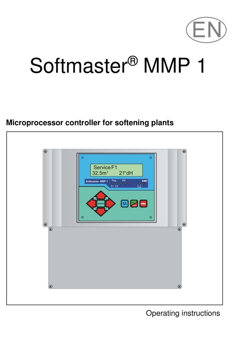
Softmaster MMP 2 User manual

Softmaster® MMP 2
Microprocessor controller for softening plants
Operating instructions

2/37
Table of contents
General notes .................................................................. 3
Introduction .................................................................. 3
Handling notes ............................................................ 3
Safety instructions ....................................................... 3
Installation and commissioning ................................... 3
General description ........................................................ 4
Views of unit ................................................................ 4
Description of display and operating features ............. 4
Display functions ......................................................... 5
Display - top line ..................................................... 5
Display - bottom line ............................................... 5
LED displays ............................................................... 6
Operating displays....................................................... 6
Error messages ........................................................... 7
Terminal block identification ....................................... 10
Functions ................................................................... 10
Description of relay outputs ....................................... 12
Filter1 / Filter2 ....................................................... 12
BV1 / BV2 ............................................................. 12
Sync ...................................................................... 12
PR1 / PR2 ............................................................. 12
Supplementary program 1 .................................... 12
Supplementary program 2 .................................... 12
AL Fault message output ("Alarm") ...................... 13
Impulse / Dosing output ........................................ 13
Description of signal inputs ....................................... 14
SVC1 and SVC2 ................................................... 14
ALC1 and ALC2 .................................................... 14
START .................................................................. 14
STOP .................................................................... 15
PROG1 and PROG2 programmable function inputs
.............................................................................. 15
IN 0/4-20mA total water hardness measuring signal
(Testomat 2000®/ECO) ......................................... 16
RS232 Serial interface .......................................... 16
Programming ................................................................ 17
Start menu ................................................................. 17
Menu selection .......................................................... 17
Input .......................................................................... 17
End menu .................................................................. 17
Information menu ...................................................... 17
Programming ............................................................. 17
Enter password ......................................................... 17
Change password ..................................................... 17
Functioning and programming description ............... 18
Switching on and voltage loss ................................... 18
Operating modes (type of plant) ................................ 18
Electric control of regeneration valves ...................... 19
Hardness unit ............................................................ 19
Exchange capacity ..................................................... 19
Regeneration ............................................................. 20
Regeneration delay .................................................... 21
Premature regeneration triggering ............................. 21
Regeneration interval ................................................. 21
Regeneration before service ..................................... 22
Minimum regeneration pause .................................... 22
Regeneration stages .................................................. 22
Supplementary program 1 ......................................... 23
Supplementary program 2 ......................................... 23
Water meter ............................................................... 24
Dosing ........................................................................ 24
Monitoring of hardness measuring instruments (ALC
inputs) ........................................................................ 24
Function START input ............................................... 25
Function STOP input ................................................. 25
Function PROG1 input ............................................... 25
Function PROG2 input ............................................... 25
Function IN 0/4-20mA input ....................................... 26
Interface ..................................................................... 26
Release ...................................................................... 26
“SERVICE” menu ......................................................... 27
Regeneration of the filter in reserve ...................... 27
Regeneration without water meter reset ............... 27
Filter change without regeneration start ................ 27
Hardness raw water .............................................. 27
Filter capacity ........................................................ 27
Regeneration information ...................................... 27
Regeneration counter ............................................ 27
Water meter ........................................................... 28
Quick motion ......................................................... 28
Operating time ....................................................... 28
Time / Date ............................................................ 28
Error history ........................................................... 29
Status history ......................................................... 29
Diagnosis (Test in/out) .......................................... 29
Software status ...................................................... 29
Menu structure ............................................................. 30
Technical appendix .................................................... 31
Connection example .............................................. 31
Connection example 24 Volt ................................. 32
Connection example 230/24 Volt .......................... 33
Example for double-filter softening plant with serial
connection (polishing filter) ........................................ 34
Example for double-filter softening plant with pilot
valves .................................................................... 35
Conformity Declaration .............................................. 36
Technical data ........................................................... 37

3/37
General notes
Introduction
These operating instructions describe the installation, operation and programming of the Softmaster MMP 2 controller.
We recommend that, while familiarising yourself with the operation of the instrument aided by these operating
instructions, you have immediate access to the operable controller in order to perform the described functions and
combinations. As certain functions are interrelated, it is advisable to follow the instructions in the given order.
Should problems or questions arise while operating the controller which are not described in these operating
instructions and/or cannot be solved, our customer service is always at your disposal.
Try to identify the problem as accurately as possible and record the actions and conditions under which it occurred.
This will enable us to offer you swift effective assistance.
Handling notes
Quick, repeated switching on/off of the controller should be avoided. Wait at least 5 seconds before switching 'on' or
'off' at the main switch.
Only operate the controller in compliance with the ambient conditions (e.g. temperature, moisture) stated in the
Technical Data. Always protect the controller against moisture.
It should never come into contact with condensation or splash water.
The warranty shall not apply if the controller is tampered with, altered, modified or repaired contrary to the instructions
described in this manual.
Before dismantling a defect controller, always write down the description of the error (failure effect).
The repair of a defective controller (irrespective of the warranty period) is only possible when the controller is
dismantled and returned to us with a description of the error.
The maximum electrical load capacity of the relay outputs and the total power rating of the plant should never be
exceeded.
The controller should only be used for its specified intended purpose.
Safety instructions
Always adhere to the following safety instructions:
The controller must be installed and operated in compliance with relevant standards (e.g. DIN, VDE, UVV) or in
accordance with regulations laid down by the respective country.
Some functions (e.g. manual filter change) allow direct manipulation of the plant (valves, pumps, etc.) without locking
or monitoring. These functions should only to be used by fully qualified personnel.
If you observe malfunctioning of the controller, switch it off immediately and inform the service personnel.
Do not attempt to repair the controller yourself (loss of warranty rights); instead always contact authorised service
personnel. This is the only way to ensure reliable and safe operation of the plant.
After a protective circuit (fuse, motor protection switch) has been triggered, attempt to eliminate the cause of
malfunctioning (e.g. clean the pump) before reactivating the protective circuit. Frequent triggering is always due to an
error which, in certain circumstances, may also cause damage to the controller.
Non-adherence to these instructions can damage the controller as well as the plant and may result in a loss of
warranty rights.
Installation and commissioning
Installation and commissioning should only be carried out by authorised technicians!
The connecting cables to the sensors should be kept as short as possible and clear of power cables. Close proximity
to strong electromagnetic radiators can lead to deviations of the display; in this case, separate interference
suppression measures should be carried out.
After installation, program the instrument with the plant-specific features and data (e.g. switch functions, conductivity
limit values, etc.). The data is permanently stored (also during power failure).

4/37
F2
T0,2A
115V
F3
T0,1A
230V
F1
T6,3A
RI1
TO1
RI2
GND
General description
Views of unit
Wall-mounted variant Panel-mounted variant
Terminal box Terminal box
Drilling scheme for wall-mounted variant Panel cut-out for panel-mounted variant

5/37
Description of display and operating features
A On/Off switch
Only the wall-mounted variant is equipped with a
lateral On/Off switch. Use this switch to switch the unit
on or off.
B Safety fuse, max. T6,3A
The safety fuse protects the outputs against overload
or a short circuit. (Inside of the unit)
D "ENTER" key
Confirm inputs and trigger functions with the ENTER
key.
E Arrow keys
Use these keys to operate the menu drive in the
display and to enter values and programming data.
F "M" key
Call the menu and return from submenu levels.
G "Run/Stop" key (“Regeneration start/stop”)
After pressing the key for 5 seconds, manual triggering
of regeneration takes place (the filter in operation is
regenerated) or a running regeneration is interrupted
(depending on the type of plant, the filter goes into
operation / ready position or reserve). If a regeneration
stop is pending, regeneration is already started after
pressing the key for a short period.
H "Alarm" key (fault OFF)
Deletes the alarm signal at output 'AL' (Alarm); a fault
display can only be deleted if the fault has been
eliminated.
I LED functions
LED symbols always signal the status of the plant,
independent of the level (menu) being worked on.
J LC display
Two lines, each line with 16 characters, backlit.
Display functions
Display - top line
The top line shows operating displays and error messages (described below).
Display - bottom line
The available (residual) capacity of the plant or filter and the raw water hardness are displayed in the bottom line.
Measured with Testomat 2000/ECO/DUO = flashing hardness unit. Entered manually = permanent display.
Service F1
12.4m
3
15°dH
Display of raw water
hardness
Measured values
(unit flashes)
Display of the
plant statuses
Display of important
plant functions
Display of the
residual filter-/plant
capacity

6/37
Service F1
12.3m
3
21.4°dH
Reg F1, R2: 43m
12.3m
3
21.4°dH
PR1 on: 10m
12.3m
3
21.4°dH
LED displays
The LEDs display operating statuses, plant functions and pending error messages:
Reg. F1 and Reg. F2 (green)
LED lights up: Filter 1 or filter 2 in regeneration.
LED flashes: A regeneration of the respective filter is triggered today at the set time (also see regeneration delay).
RP1 and RP2 (green)
LED lights up: Supplementary program 1 or 2 active, relay PR1 or PR2 switched.
LED flashes (only RP2): Relay RP2 not switched, “OFF” phase of supplementary program 2 active.
Dosing message (green)
LED lights up as long as the impulse output has been activated.
Warning message “Chemical low” (yellow)
LED lights up: The brine deficiency contact is active (also see PROG1 input).
Error message “Alarm” (red)
LED lights up: Alarm relay activated, error message not confirmed yet and error still occurring.
LED flashes: Alarm relay not active any more, error message has been confirmed but the error is still occurring.
As long as an error is still occurring, it is shown alternately with the operating display.
Operating displays
Each status change is stored in the status registration (e.g. manual regeneration, filter change).
Filter 1 in operation with 12.3m3 of residual capacity (still available soft water
quantity) and 21.4°dH of current total water hardness.
Display occurs with single-filter and double-filter plants.
or:
Operation F2 Filter 2 in operation
Operation F1 + F2 Filter 1 and filter 2 in operation (parallel or serial mode, filter 1 is first)
Operation F2 + F1 Filter 2 and filter 1 in operation (only serial mode, filter 2 is first)
Example: Filter 1 in regeneration: with regeneration stage R2 and remaining
stage time of 43 minutes. LED Reg. F1 lights up.
or:
Reg F2, R1: 7m Example: Filter 2 in regeneration: with stage R1 and remaining stage time of 7 minutes.
Supplementary program PR1 active prior to regeneration, remaining time of
10 minutes. LEDs Reg. F1 and ZP 1 light up.
Filter 1 Filter 2 Aux.
prog. 1
Alarm message
„Brine/Chemical low“
Error
message
in regeneration
Aux.
prog. 2
Dosing
message

7/37
Reg. STOP
12.3m3 21.4°dH
Power failure
Power failure
set clock !
Plant override
Regeneration stopped via STOP input or regeneration start delayed.
Continue regeneration by pressing the “Run/Stop” key.
Error messages
In addition to the displayed error messages, the red LED “Alarm” lights up or flashes.
Alternate display of all error messages and operating displays.
Each occurred error is stored in the error registration.
Error message “Power failure”
or
Message after each switching on: “Power failure”. Check the time and, if necessary, set the time if “set clock !“ is
displayed. After this, the unit is without a real-time clock (plug-in card RTC/RS232).
After switching on or after voltage recovery, the controller starts with the last active status. A running regeneration
continues.
Check the plant for possible negative results due to power failure (e.g. exhaustion caused by washing for too long in
the regeneration stage “Wash out”).
All stored values remain stored even during a power failure.
Confirm the fault display with the “Horn” key.
Error message “Plant override”
Regeneration triggering via contact at the start input or via to high
consumption while a filter is still being regenerated.
In multi-filter plants it can occur that a filter is in regeneration and a second filter is also waiting to be regenerated. This
status can occur if the soft water consumption is very high, e.g. when filling a swimming pool. If this scenario occurs,
the plant will only provide raw water to the consumers. If only soft water should be provided, the soft water supply to
the consumers has to be closed.
Wait until the current filter regeneration has finished and then open the soft water supply to the consumers. The
controller will always automatically complete regeneration of this filter.
Find and eliminate the fault and confirm the fault display via the ”Horn” key.
If regeneration is really necessary again (triggered via consumption measurement), regeneration will occur at the end
of the current regeneration.
If you have programmed a minimum regeneration interval, regeneration will be started after this period has expired.
With triggering via a contact at the START input, you have to start regeneration manually via the ”Run/Stop” key.

8/37
Min. reg. Pause
Max. regenerat.
Err.hardn.meas.
Error T2000 1
Error T2000 2
Error message “Minimum regeneration interval not achieved”
Regeneration triggering via contact at the start input or if consumption is too
high during the programmed time after a completed filter regeneration.
Confirm the fault display with the “Horn” key.
Regeneration requested via the water consumption is executed after the programmed period.
Regeneration triggering via the START contact is ignored. Check the plant and trigger a required regeneration
manually. The error message is subsequently deleted.
Error message “Maximum number of regenerations achieved”
The entered maximum number of possible regenerations has been achieved.
The current status of the regeneration meter is shown in the SERVICE menu
under “Reg. meter”.
In addition to the error message, the yellow warning light “Chemical/brine low” lights up.
Confirm the fault display with the “Horn” key. The message is displayed until the regeneration meter is deleted.
Delete the regeneration meter in the SERVICE menu under “Reg. meter”.
Error message “Incorrect hardness measurement”
The connected water hardness measuring instrument (e.g. Testomat 2000)
gives an incorrect current signal 4-20mA.
Confirm the fault display with the “Horn” key.
Check the settings of the current input. Programming has to correspond to the set signal level of the measuring
instrument. Check the signal levels in the SERVICE menu under “Diagnosis”.
Error message “Error total water hardness measuring instrument”
The connected water hardness measuring instrument (e.g. Testomat 2000)
for the total water hardness gives an alarm. The alarm signal occurs at
contact input ALC1.
Confirm the fault display with the “Horn” key.
Check the connected unit. The error display is deleted after the alarm signal has ceased.
Error message “Error soft water hardness measuring instrument”
The connected water hardness measuring instrument (e.g. Testomat 2000)
for soft water monitoring gives an alarm. The alarm signal occurs at contact
input ALC2.
Confirm the fault display with the “Horn” key.
Check the connected unit. The error message is deleted after the alarm signal has ceased.
Regeneration triggering via START contact is suppressed as, in the case of quality-controlled plants, the START
signal is usually triggered by the instrument for soft water monitoring if the hardness is exceeded.

9/37
Error Filter 1
Error Filter 2
Chemicals low
Chem. overflow
Reg. STOP/Hold
Error message “Error operating position filter 1”
The central control valve or pilot distributor of filter 1 does not give a signal in
the operating position or is not running synchronously.
The signal does not occur at contact input SCV1.
Confirm the fault display with the “Horn” key.
Check the connected central control valve or pilot distributor of filter 1.
The error display is deleted after the fault has been eliminated.
Error message “Error operating position Filter 2”
The central control valve or pilot distributor of filter 2 does not give a signal in
the operating position or is not running synchronously.
The signal does not occur at contact input SCV2.
Confirm the fault display with the “Horn” key.
Check the connected central control valve or pilot distributor of filter 2.
The error display is deleted after the fault has been eliminated.
Error message “Chemicals low”
The brine or chemical tank is empty.
The EMPTY signal occurs at contact input Prog1 and the input is programmed
as “Chemicals low” contact.
In addition to the error message, the yellow warning light “Chemical/brine low” lights up.
Confirm the fault display with the “Horn” key.
Check the brine tank and desalination valve or the automatic refilling of the measuring vessel. The error display is
deleted after the fault has been eliminated.
Error message “Chemicals overflow”
The brine or chemical tank is overflowing.
The overflow signal occurs at contact input Prog2 and the input is
programmed as “Chem. overflow” contact.
Confirm the fault display with the “Horn” key.
Check the brine tank and desalination valve or the automatic refilling of the measuring vessel. The error display is
deleted after the fault has been eliminated.
Error message “Regeneration stopped”
If the program has been stopped via an external switch (STOP input) prior to
or during regeneration and if you have programmed the alarm message for
the STOP input, the display "Reg. STOP/Hold" will appear as an error
message.
Confirm the fault display with the “Horn” key.
The display ceases as soon as the switch reopens and the program cycle is continued.

10/37
Terminal block identification
Functions (IN = input, OUT = output)
No.
Terminal
Type
Function
Note
PE
IN
4x Mains
-
Protective earth
N
L IN Mains, N = Neutral
Mains, L = Live
Mains-input
230 - 240 V AC
n
l OUT 8x Neutral switched
8x Live switched Mains voltage, max. 4 A
1
2
3
Filter1 OUT
Filter1, 7 - normally open
Filter1, c - common
Filter1, 6 - normally closed
Volt-free relay output
max. load 240 V AC, 4 A
4
5
6
BV1 OUT
Service valve filter 1, no - normally open
Service valve filter 1, c - common
Service valve filter 1, nc - normally closed
Volt-free relay output
max. load 240 V AC, 4 A
7
8
9
Filter2 OUT
Filter2, 7' - normally open
Filter2, c - common
Filter2, 6' - normally closed
Volt-free relay output
max. load 240 V AC, 4 A
10
11
12
BV2 OUT
Service valve filter 2, no - normally open
Service valve filter 2, c - common
Service valve filter 2, nc - normally closed
Volt-free relay output
max. load 240 V AC, 4 A
13
14
15
Sync OUT
Sync, 8 - normally open
Sync, c - common
Sync, PR
-
normally c
losed
Volt-free relay output
max. load 240 V AC, 4 A
16
17
18
PR1 OUT
Supplementary program 1, no -normally open
Supplementary program 1, c -common
Supplementary program 1, nc
-
normally closed
Volt-free relay output
max. load 240 V AC, 4 A
19
20
21
PR2 OUT
Supplementary program 2, no -normally open
Supplementary program 2, c -common
Supplementary program 2, nc
-
normally closed
Volt-free relay output
max. load 240 V AC, 4 A
22
23
24
AL OUT
Fault message output, no - normally open
Fault message output, c - common
Fault message output , nc
-
normally closed
Volt-free relay output
max. load 240 V AC, 4 A
25
26
WM1
2
IN Water meter input 1
common load for inputs
See water meter description!
27
28
WM2
2 IN Water meter input 2
common load for inputs
See water meter description!
29
30
+12V
2
OUT 12V-supply for turbine
common load for inputs
See water meter description!
( Current max. 50mA )
31
32
SVC1
2
IN Synchronous message filter 1 (operating pos.)
common load for inputs
Only for volt-free normally open/ normally
closed contact!
33
34
SVC2
2 IN Synchronous message filter 2 (operating pos.)
common load for inputs
Only for volt-free normally open/ normally
closed contact!
35
36
ALC1
2
IN Error message Testomat 1 (total water)
common load for inputs
Only for volt-free normally open/ normally
closed contact!
37
38
ALC2
2
IN Error message Testomat 2 (soft water)
common load for inputs
Only for volt-free normally open/ normally
closed contact!
39
40
START
2 IN external regeneration start
common load for inputs
Only for volt-free normally open/ normally
closed contact!
41
42
STOP
2
IN external regeneration stop
common load for inputs
Only for volt-free normally open/ normally
closed contact!
43
44
PROG1
2 IN Brine level-switch EMPTY / brine deficiency
common load for inputs
Only for volt-free normally open/ normally
closed contact!
45
46
PROG2
2 IN Brine level-switch FULL / brine overflow
common load for inputs
Only for volt-free normally open/ normally
closed contact!
47
48
49
50
-
-
-
-
OUT/
IN
Free for later add-ons (e.g. optional serial interface
RS485 instead of RS232)
Not available yet !
51
52
Impuls
2 OUT Dosing impulse (open collector)
common load
Max. load 50mA, see “impulse/dosing
output” description
53
54
- - - -
55
56
- - - -
57
58
2
IN 0/4-20mA IN
common load
Measuring value for total water hardness from
Testomat
Testomat ECO or Testomat 2000 with
SK910, 0/4-20mA output

11/37
Continuation of terminal block identification
No.
Terminal
Type
Function
Note
RI1
TO1
RI2
GND
IN/
OUT
Serial interface RS232, RxD
Serial interface RS232, TxD
Serial interface RS232, DTR/DSR
Serial interface RS232, load
Parallel to D-SUB-plug RS-232 (J3)
Terminal blocks for mains supply and relay outputs
Terminal block for inputs and interface
Serial interface RS232
PIN 2 - RxD
PIN 3 - TxD
PIN 4 - DSR, DTR
PIN 5 - GND, load
Please observe that the peripheral devices are
connected via a neutral modem cable!

12/37
Description of relay outputs
Filter1 / Filter2 pilot distributor or central control valves 1 and 2
Connect the regeneration valves (central control valves) or pilot distributors which are controlled via an electric
change-over or impulse switch to these relay outputs.
Change-over: In the case of change-over switches, the output changes after each regeneration stage.
Impulse: In the case of impulse switches, the output switches for 40 seconds (terminal 7 or 7').
Pilot valves: For pilot valves for controlling regeneration valves like, e.g., Siata V250/V360 etc.
The neutral position of the relay is the same during de-energized control and in the operating position of the filter:
contact on terminal 6 or 6'.
Set the control type under menu option
"M" BASIC PROGRAM VALVE TYPE
If the regeneration valves or pilot distributors are equipped with a volt-free message contact for the operating position,
it is possible to connect them to the inputs "SVC1" and "SVC2". Faults of the valve / pilot distributor are then
monitored and evaluated by the controller in accordance with the programming (see SVC1/SVC2 service contact).
BV1 / BV2 Service valves Filter 1 and 2
The service valves of the filter can be designed as normally closed or opened. Please connect valves which are
normally closed to the terminals BV1-nc / BV2-nc. For safety reasons, the service valves should be designed in a
way that they open under driving voltage.
Note!
In the operating mode “double-filter serial connection“, the outputs BV1 and BV2 are used for filter change-over. For
this reason, they are not freely available. Please observe the plant example notes in the technical appendix.
Sync Synchronous contact / Regeneration message
(formerly: 8th-contact at MMP70/81)
After a power failure (e.g. during regeneration) or if faults occur, it is often necessary to synchronize the valves or pilot
distributors with the controller. It is even necessary to connect regeneration valves/pilot distributors with change-over
control and an odd number of (electric) regeneration settings to the synchronous contact. Due to this, the regeneration
valve / pilot distributor returns to the operating position after regeneration. The connection takes place at terminal
Sync - 8.
The connection Sync - PR can be used for the external display of the program cycle (regeneration) or for the control of
a contactor or magnetic valve during regeneration.
PR1 / PR2 Supplementary program 1 / 2
The volt-free outputs PR1 (supplementary program 1) and PR2 (supplementary program 2) can be used for various
functions:
Supplementary program 1
Supplementary program 1 is used, e.g., for the automatic filling of the brine tank or for the control of an additional
valve - prior to, during or after regeneration with a programmable operating time. If output PR1 is switched, the LED
"ZP1" lights up as a check.
Program the function under menu option (see basic programming “Aux prog. 1"):
"M" BASIC PROGRAM Aux prog. 1
Supplementary program 2
Supplementary program 2 can only be switched on and off twice during regeneration. If output PR2 is switched, the
LED "ZP2" lights up as a check.
Program the function under menu option (see basic programming “Aux prog. 2"):
"M" BASIC PROGRAM Aux prog. 2
Note!
Supplementary programs 1 and 2 are used for filter change-over in the operating mode “double-filter serial
connection“. For this reason, they are not freely available. Outputs BV1 and BV2 also have a special function. Please
observe the plant example notes in the technical appendix.
The two supplementary programs are also not freely available when using pilot distributors (e.g. Siata V250/V360).
(Programming: "M" BASIC PROGRAM Valve type Pilot valves)
Please also observe the example in the technical appendix.

13/37
AL Fault message output ("Alarm")
Output "AL" is a volt-free change-over relay contact. During trouble-free operation, the contact between the terminals
22 - 23 is closed and the one between terminals 23 - 24 is open. During power failure or if an error occurs, the
contact between terminals 23 - 24 is closed and the one between terminals 22 - 23 is open.
The controller monitors several plant statuses. Output "AL" remains activated (terminals 23 - 24 closed) until the fault
ceases and is confirmed.
A fault is displayed with the red LED "Error message" and in the display.
The fault message signal at output "AL" is deleted by confirming the fault with the "Horn" key.
The fault display can only be deleted if the fault has been eliminated.
The following faults activate output "AL" and are displayed if the softening plant or valves/pilot distributors have been
equipped with the appropriate contacts:
Statuses which always trigger a fault message:
Power failure
Plant override (regeneration start during filter regeneration)
Error hardness measurement (if current input has been programmed as 4-20mA and no current is measured)
Error messages which occur depending on the programming:
Minimum regeneration interval not achieved
Maximum number of regenerations achieved (when reaching the regeneration meter)
Regeneration stopped via Stop input
Error Testomat 1 (ALC1)
Error Testomat 2 (ALC2)
Error Filter 1 (SVC1)
Error Filter 2 (SVC2)
Depending on programmed PROG1 input:
Brine/Chemicals low
Depending on programmed PROG2 input:
Brine/Chemicals overflow
Impulse / Dosing output
Use output "Impulse" to control a dosing pump if dosing should take place during operation. For this, a water meter
has to be connected to the input "WM1" or "WM2". The impulse interval in litres can be set (litre/impulse).
Example:
An impulse lasting 1 second should be given per 50 litres : L/Imp. = 50.0, I.duration = 1.0sec
A dosing distance of less than 50 L/Imp should not be entered for this water meter! The minimum dosing impulse
distance corresponds to the water meter constant.
"M" Basic program Dosing
"M" Basic program Water meter 1
"M" Basic program Water meter 2
The output is an open collector transistor with a max. load capacity of 50mA/30V.

14/37
Description of signal inputs
Note!
Connect the signal inputs "SVC1", "SVC2", "ALC1", "ALC2", "START", "STOP", "PROG1" and "PROG2" only to volt-
free contacts!
SVC1 and SVC2 check inputs operating position valve
When using pilot distributors or regeneration valves equipped with a volt-free signal contact for the operating position,
it is possible to connect this contact to input "SVC1" for filter1 and "SVC2" for filter2. An operating fault is then
monitored and, depending on the programming, evaluated by the controller.
Function Test time Type of contact Type of contact
connection
Action
SVC1, SVC2
S signal contacts for
operating position of
the filters
1 - 99 sec.
Normally closed Contact during operation
- Entry in error list
programmable:
S Continuous alarm
Normally open Contact during
regeneration
Please program the inputs according to the operating mode of the signal contacts under:
"M" Basic program Funct. SVC 1
"M" Basic program Funct. SVC 2
ALC1 and ALC2 Alarm inputs for hardness measuring instruments (Testomat)
If the softening plant is equipped with hardness measuring instruments (e.g. Testomat 2000/ECO), we recommend
monitoring these instruments for faults. Operating faults and hardness monitoring instrument errors are then
monitored and, depending on the programming, evaluated by the controller.
Function
Type of contact
Test time
Action
ALC1
S Alarm input "Hardness
measuring instrument",
on the input side or
Testomat 2000 DUO programmable
normally closed/
normally open
programmable
1 - 99 seconds
S Calculate filter performance/soft
water quantity with
programmable water hardness
(with measured total water
hardness)
S with DUO: regeneration only
quantity-dependent, ignore
START signal
S Entry in error list
programmable:
S
Continuous alarm
ALC2
S Alarm input "Hardness
measuring instrument",
on the output side
programmable
normally closed/
normally open
programmable
1 - 99 seconds
S Regeneration only quantity-
dependent, ignore START signal
S Entry in error list
programmable:
S
Continuous alarm
START external regeneration start
Connection for hardness monitoring instrument (e.g. Testomat)
Functio
n
Type of contact
Test time
Action
START
S Start of regeneration
after filter exhaustion
programmable
normally closed/
normally open
programmable
1 - 99 seconds
S Filter change (only serial and
double-filter operation)
S Regeneration start
S
Entry in history
Install a hardness monitoring instrument at the input/soft water side to avoid hard water (e.g. due to insufficient
regeneration) being supplied by the plant.
If the limit value is exceeded (the limit value contact of the Testomat switches), the filter in the reserve/ready position
goes into operation after a programmed test time and the exhausted filter is regenerated.

15/37
"M" Basic program Funct. Start
Note!
If the plant is operated with a hardness monitoring instrument for triggering regeneration, we recommend monitoring
the trouble-free functioning by connecting the alarm contact of the Testomat to input ALC2.
STOP external regeneration interruption/prevention
Connection for volt-free contact
Function
Type of contact
Test time
Action
STOP
S Regeneration stop
programmable
normally closed/
normally open
programmable
1 - 99 seconds
S Regeneration interruption or
prevention of a pending
regeneration
During regeneration, it might be necessary to interrupt the regeneration externally via a switch (e.g. pressure switch at
the input). A running regeneration can be stopped or a pending regeneration delayed via a contact at the STOP input.
The message: “Reg. STOP” appears on the display.
"M" Basic program Funct. Stop
PROG1 and PROG2 programmable function inputs
Inputs "PROG1" and "PROG2" can be used to connect level transmitters (monitoring or automatic filling of the brine
tank) for an extended checking of the plant.
Function
Type of contact
Test time
Action
PROG1
S Level transmitter input:
"Chem. low" alarm
or
“EMPTY” level brine
programmable
normally closed/
normally open
programmable
1 - 99 seconds
programmable:
S Brine filling valve opens (relay
output PR1 in connection with
supplementary program 1)
S Continuous alarm
S Entry in error list
PROG2
S Level transmitter input:
"Chem. overflow" alarm
or
“FULL” level brine
programmable
normally closed/
normally open
programmable
1 - 99 seconds
programmable:
S Brine filling valve closes (relay
output PR1 in connection with
supplementary program 1)
S Continuous alarm
S Entry in error list
"M" Basic program Funct. PROG1
"M" Basic program Funct. PROG2
Example:
The supplementary program 1 with input PROG1 has to be
started for automatic filling. Please program the supplementary
program 1 accordingly:
"M" Basic program Aux prog. 1
Start PROG1
The filling valve closes again if the level switch “FULL” opens at
PROG2 input.
Brine proportion tank
“FULL”
Brine deficiency
as overflow
or
Brine
suction line
To input suppl. PR1:
brine filling valve
Brine supply
as “EMPTY”
or
Overflow
PROG2:
PROG1: as “EMPTY”
or
as “EMPTY”
or

16/37
IN 0/4-20mA total water hardness measuring signal (Testomat 2000®/ECO)
Function
Connection
Test time
Action
Input for interface0/4 - 20
mA
Terminals 57 / 58
load type 200 Ohm
- - Total water hardness (measuring
signal of the Testomat 2000®/ECO)
The measuring input IN 0/4-20mA (only in connection with the optional plug-in card disinfection DES2002, Art.no.
37262) for connecting a hardness measuring instrument Testomat 2000/ECO with 0/4-20mA output is used for the
automatic calculation of the filter capacity (available soft water quantity in m³) on the basis of total water hardness.
Program the measuring range of the used reagent in the menu:
"M" Basic program Fct. IN 0-20mA max. h.
If the filter performance is to be calculated automatically, activate the function in the menu:
"M" Basic program Exchange cap. Calc. f. cap.
Note!
In the case of automatic filter capacity calculating, we recommend monitoring the trouble-free functioning of the
hardness measuring instrument. For this, please connect the alarm contact of the Testomat 2000/ECO with the alarm
message input ALC1. This way, an incorrect calculation can be avoided when faults occur. The controller then
calculates the filter capacity with the programmed total water hardness. If the input is programmed as 4-20mA input
and there is no signal (< 4mA), the calculation of the filter capacity also takes place with the programmed total water
hardness.
Request the total water hardness in the service menu (e.g.):
"M" Service Hardness raw water Measured: 16.7°dH
RS232 Serial interface (terminal block left and 9-pole D-Sub)
Function
Connection
Test time
Action
serial interface
RS 232
see terminal block
identification on
page 7
- - Connection to parameterisation
and remote maintenance
Activate the function of the output in the menu accordingly:
"M" Basic program Interface

17/37
MENU
Service
Information
Basic program
“M“
BASIC PROGRAM
Password input
Change password
Password:
Programming
Start menu
Call the menu with the "M" key.
Menu selection
The current line position is displayed as a heading in CAPITAL LETTERS. Activate the
selected/displayed menu option with the "ENTER" key, i.e. you "jump" into a submenu.
Call the next menu point with the "DOWN" arrow key: thus you "scroll" the menu.
Input
Inputs are only possible in the BASIC PROGRAM menu and in some SERVICE
menu options.
Select a programming step with the "DOWN" and "UP" arrow keys and activate the
input function with the "ENTER" key.
When entering digits, the digit/position to be changed flashes.
Change to the next or previous digit (now flashing) with the "Right" and "Left" arrow
keys.
Change the value or selection with the "DOWN" and "UP" arrow keys.
Selected functions are marked with a T if selection is possible.
Terminate the input function with "ENTER".
Change to the higher-order menu with the "M" key.
End menu
Return to the higher-order menu with the "M" key. After returning from the highest menu level, the unit is once again in
the display function.
Information menu
"M" Information
Request the current settings without entering a password in the information menu.
The information menu is also displayed if an incorrect password has been entered.
Programming
"M" Basic program
Enter password
The programming menu is protected with a 3-digit password (number between 000
and 999) in order to prevent unauthorised intervention in the programming.
Enter the password under "M" Basic program Password input
and confirm the input with “ENTER”.
You are now in the menu BASIC PROGRAM
Change password
Enter or change your individual password at any time. For this, enter the old password (OLD: )
and then the new one (NEW: ).
When restoring the factory settings, the password is also deleted and reset to 000!

18/37
OPERATING MODE
Single-filter -
2
-
F.altenate
2-F.parallel -
2-F.serial -
Functioning and programming description
Switching on and voltage loss
After switching the unit on and after each voltage loss, the plant automatically returns to the last active position.
Operating modes (type of plant)
Control the following softening plants with the controller Softmaster MMP2:
Single-filter plant
Only one filter (filter 1) in operation, no soft water is available during regeneration.
Programming: “Single- filter ”
Double-filter change-over mode
Alternately, one filter in operation, one filter in reserve/ready position or in
regeneration. Usually, soft water is always available.
Programming: “2-F. alternate ”
Double-filter parallel mode
Both filters in operation. Usually, soft water is always available.
With the parallel mode, only quantity-dependent regeneration triggering should be selected. Only enter the capacity of
one filter.
When commissioning the plant, both filters are regenerated, one after the other. After this, soft water is removed. After
removing a filter‘s soft water, a regeneration is started. At this point of time, both filters are half exhausted. After
regeneration, the regenerated filter has full soft water capacity while the other filter is available with its residual
capacity.
Programming: “2-f. parallel ”
Double-filter serial mode
Both filters in operation. Alternately, one filter is first filter, the other one is connected downstream as a “polishing
filter”. After removing a filter‘s soft water, the first filter is regenerated and the second filter becomes first filter. The
regenerated filter becomes “polishing filter”. Usually, soft water is always available.
Programming: “2-f. serial T”
Note!
As the supplementary programs 1 and 2 are used for the filter change-over in this operating mode, they are not freely
available. Outputs SV1 and SV2 also have a specific function. Please observe the notes on the plant example in the
technical appendix.

19/37
6, 6'
7, 7'
Operation/
neutral position
1. Stage
2. Stage
3. Stage
Operation/
neutral position
Position
Relay outputs
nc
no
PR1/2
Filter 1/2
VALVE TYPE
Change
-
over
Impulse
-
Pil
ot
valves
-
HARDNESS UNIT
°dH
°f
-
ppmCaCO3
-
EXCHANGE CAP.
m
3
°dH 100
Calc. f. cap. -
Electric control of regeneration valves
It is possible to use central control valves or pilot distributors with up to 8
stage/positions with impulse or change-over control as well as pilot valves with 4
positions.
In the case of pilot valves, the number of stages is set to a maximum of 3 regeneration
stages as these valves usually have 4 positions.
Examples for 4-stage valves/pilot distributors:
as change-over
In the case of change-over switches, the output
changes after each regeneration stage. If the number
of mechanical positions is odd, the return movement to
the operating position has to take place via the
synchronous contact (operating switch).
as impulse
In the case of impulse switches, the output switches
for 40 seconds at the beginning of each stage
(terminal 7 or 7').
In the case of plants with pilot valves, the relay outputs
filter 1/2 and the supplementary program PR1/2
change after each regeneration stage.
For a description of the connection, see example in the
technical appendix.
with pilot valves
Hardness unit
Enter and display the total water hardness in different units:
German hardness = °dH
French hardness = °f (1.79 °f × 1 °dH)
ppm as CaCO3 = ppmCaCO3 (17.9 ppmCaCO3 × 1 °dH)
Enter the exchange capacity according to the unit (in the next menu option).
Exchange capacity
The controller calculates the filter capacity of available soft water quantity in m³. For this, enter the exchange capacity
of a filter in m3x°dH, m3x°f or gCaCO3 and the current total water hardness (in the “Service” menu).
Manual calculation of the filter capacity
If the function “calc. f. cap.” is not activated, the filter capacity (often also
described as filter performance), i.e. the available soft water quantity, is calculated on
the basis of the entered total water hardness.
"M" Service Hardness raw water Setting: 016°dH (example)
(in m3)
6, 6'
7, 7'
Operation/
neutral position
1. Stage
2. Stage
3. Stage
Operation/
neutral position
Position
Contact
6, 6'
7, 7'
Operation/
neutral position
1. Stage
2. Stage
3. Stage
Operation/
neutral position
Position
Contact
40s 40s 40s 40s
Filter per
formens
=
Exchanger
capacity
Raw water
hardness

20/37
Automatic calculation of the filter capacity
If the total water hardness varies strongly, it is also possible to automate the calculation of the filter capacity (available
soft water quantity). The total water hardness is measured with an analysis instrument (Testomat 2000/ECO) and
requested at the measuring input IN 0/4-20mA. The request interval for the calculation is one minute. If the alarm
contact of the analysis instrument is connected to the alarm message input ALC1, the controller measures the filter
capacity if the measuring instrument is not working correctly on the basis of the entered total water hardness.
If the filter capacity is to be calculated automatically, activate the function in the menu:
"M" Basic program Exchange cap. Calc. f. cap.
Request the total filter capacity (available soft water quantity after regeneration) in the service menu:
"M" Service Exchange cap.
The remaining residual filter capacity or residual soft water quantity is shown in the operating display.
Regeneration
Regeneration start
Regeneration of an exhausted filter can be started via different triggering criteria:
- Manually by operating the “Run/Stop” key (press the key for 5 seconds)
- After removing the set soft water quantity (filter capacity)
- After the end of the set daily interval at the programmed time
- Via start impulse from the water hardness measuring instrument (Testomat)
Manual regeneration
A filter change takes place when starting regeneration manually. The filter in operation is regenerated and the filter in
the reserve/ready position is put into operation.
Quantity-dependent regeneration
In most cases, we recommend recording the removed soft water quantity and to regenerate the filter when the
calculated filter capacity has been reached. The controller calculates the filter capacity on the basis of the
programmed exchanger capacity (m3 x °dH) and total water hardness. Quantity recording takes place via a water
meter in the filter/plant output.
Program regeneration delay in order to avoid a regeneration taking place at an inappropriate time for the operation. A
necessary regeneration only starts at the set time, e.g. 20:00 (see "Regeneration delay").
During change-over mode, there is an immediate change to the filter in reserve and regeneration of the exhausted
filter is caught up on at the set time.
The filter can be overrun due to delayed regeneration. Additionally select a premature regeneration triggering (reg.
start at x% of residual filter capacity) to avoid this happening.
Time-dependent regeneration
If there should only be a time-controlled regeneration of the plant, program the daily interval and the time of
regeneration (regeneration delay = ON).
Quality-controlled regeneration
Using the internal control functions in connection with a water hardness measuring instrument (e.g. Testomat
2000/ECO), it is possible to construct a convenient and reliable plant. The water hardness measuring instrument
monitors the soft water hardness and sends a start signal to the controller in order to trigger regeneration if the set
limit value has been reached.
Due to the combination of the different control possibilities, it is possible to assure the greatest possible operating
safety.
Stop or delay the regeneration
Manually cancel a running regeneration at any time with the “Run/Stop” key. A regeneration can be delayed or a
running regeneration stopped via a contact at the “Stop” input.
Regeneration stages
Up to 8 regeneration stages can be programmed. Exception: In the case of pilot valves, the number of stages is set to
a maximum of 3 regeneration stages as these valves usually have 4 positions.
The minimum duration per stage is 1 minute (operating time of the valve/pilot distributor), the maximum duration is 99
minutes.
Table of contents
Other Softmaster Controllers manuals
Popular Controllers manuals by other brands
Johnson Controls
Johnson Controls Metasys VMA1610 installation instructions
Siemens
Siemens SIMATIC Mobile Client900WXN operating instructions
TP-Link
TP-Link AC50 Configuration guide
Enovation Controls
Enovation Controls Murphy EMS PRO LITE Installation and operation manual

Mitsubishi Electric
Mitsubishi Electric SV13/22 Programming manual
dymax
dymax BlueWave MX-Series user guide
