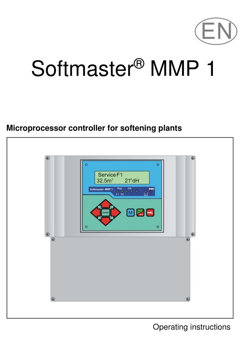
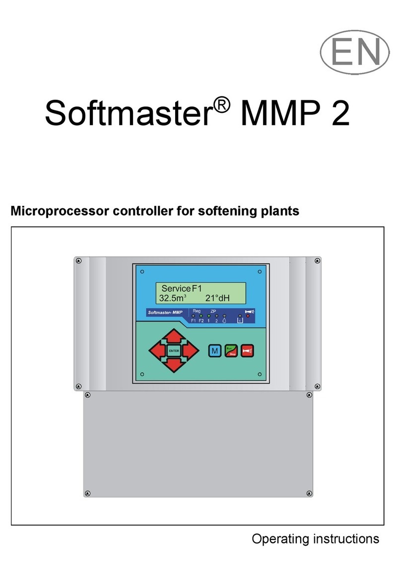
Softmaster MMP compact User manual

Softmaster®MMP compact
Controller for softening plants
Operating instructions

2/30
Table of Contens
General notes .................................................................3
Introduction..................................................................3
Handling notes ............................................................3
Safety instructions.......................................................3
Installation and commissioning...................................3
General description........................................................4
Views of the instrument...............................................4
Description of display and operating features.............5
Display functions .........................................................5
Display top line.......................................................5
Display bottom line.................................................5
LED displays................................................................6
Operating displays.......................................................6
Error messages...........................................................7
Terminal block identification.........................................9
Functions.....................................................................9
Description of the relay outputs.................................10
Filter 1 / Filter 2....................................................10
Sync .....................................................................10
BV1 / BV2.............................................................10
AL/PR Fault message output / additional program10
Description of the signal inputs .................................11
START .................................................................11
STOP ...................................................................11
PROG...................................................................11
LL .........................................................................12
WM.......................................................................12
Programming................................................................13
Menu start............................................................13
Menu selection / Selection...................................13
Input .....................................................................13
Menu end .............................................................13
Information menu.................................................13
Programming........................................................13
Enter password....................................................13
Change password................................................13
Switching on and power failure .................................14
Operating modes (plant type)....................................14
Electrical control of the regeneration valves..............14
Hardness unit............................................................15
Exchanger capacity...................................................15
Regeneration.............................................................15
Regeneration delay................................................... 16
Early regeneration triggering..................................... 16
Regeneration interval................................................ 17
Regeneration prior to operation................................ 17
Minimum regeneration interval ................................. 17
Regeneration stages................................................. 17
Fct. Out AL/PR.......................................................... 18
Additional program PR.............................................. 18
Water meter.............................................................. 18
Function START input .............................................. 19
Function STOP input ................................................ 19
Function PROG input................................................ 19
Chemical tank monitoring (LL input)......................... 19
Language.................................................................. 19
“SERVICE” menu ......................................................... 20
Regeneration of the reserve filter........................ 20
Filter change without regeneration start .............. 20
Hardness raw water............................................. 20
Filter capacity....................................................... 20
Regeneration information .................................... 20
Regeneration meter............................................. 20
Water meter......................................................... 21
Fast mode............................................................ 21
Operating hours................................................... 21
Time / Date.......................................................... 21
Error history......................................................... 21
Status history....................................................... 22
Diagnosis............................................................. 22
Software status.................................................... 22
Menu structure............................................................. 23
Technical Appendix..................................................... 24
Connection example for control valves (415, 426,
427, 441) from WWWS............................................ 24
Connection example for control valve Autotrol 952.. 25
Connection example for control valve Fleck2900
(single-filter plant)..................................................... 25
Connection example for control valve Fleck2900
(double-filter plant).................................................... 26
Connection example for control valve Fleck9000
(single-filter plant)..................................................... 27
Conformity Declaration............................................. 29
Technical data .......................................................... 30

3/30
General notes
Introduction
These operating instructions describe the installation, operation and programming of the Softmaster MMP compact
controller. We recommend that, while familiarising yourself with the operation of the instrument aided by these
operating instructions, you have immediate access to the operable controller in order to perform the described
functions and combinations. As certain functions are interrelated, it is advisable to follow the instructions in the given
order.
Should problems or questions arise while operating the controller which are not described in these operating
instructions and/or cannot be solved, our customer service is always at your disposal.
Try to identify the problem as accurately as possible and record the actions and conditions under which it occurred.
This will enable us to offer you swift effective assistance.
Handling notes
Quick, repeated switching on/off of the controller should be avoided. Wait at least 5 seconds before switching'on'or 'off' at
the main switch.
Onlyoperate the controller in compliance with the ambient conditions (e.g. temperature, moisture) stated inthe Technical
Data. Always protect the controller against moisture.
It should never come into contact with condensation or splash water.
The warranty shall not apply if the controller is tampered with, altered, modified or repaired contrary to the instructions
described in this manual.
Before dismantling a defect controller, always write down the description of the error (failure effect).
The repair of a defective controller (irrespective of the warranty period) is only possible when the controller is dismantled
and returned to us with a description of the error.
The maximum electrical load capacityof the relayoutputs and the total power rating of theplant should never beexceeded.
The controller should only be used for its specified intended purpose.
Safety instructions
Always adhere to the following safety instructions:
The controller must be installed and operated in compliance with relevant standards (e.g. DIN, VDE, UVV) or in
accordance with regulations laid down by the respective country.
Some functions (e.g. manual filter change) allow direct manipulation of the plant (valves, pumps, etc.) without locking
or monitoring. These functions should only to be used by fully qualified personnel.
If you observe malfunctioning of the controller, switch it off immediately and inform the service personnel.
Do not attempt to repair the controller yourself (loss of warranty rights); instead always contact authorised service
personnel. This is the only way to ensure reliable and safe operation of the plant.
After a protective circuit (fuse, motor protection switch) has been triggered, attempt to eliminate the cause of
malfunctioning (e.g. clean the pump) before reactivating the protective circuit. Frequent triggering is always due to an
error which, in certain circumstances, may also cause damage to the controller.
Non-adherence to these instructions can damage the controller as well as the plant and may result in a loss of warranty
rights.
Installation and commissioning
Installation and commissioning should only be carried out by authorised technicians!
The connecting cables to the sensors should be kept as short as possible and clear of power cables. Close proximity
to strong electromagnetic radiators can lead to deviations of the display; in this case, separate interference
suppression measures should be carried out.
After installation, program the instrument with the plant-specific features and data (e.g. switch functions, conductivity
limit values, etc.). The data is permanently stored (also during power failure).

4/30
General description
Views of the instrument
Terminal box Serial interface RS232
Drilling-scheme

5/30
Description of display and operating features
A On/Off switch
Use this switch to switch the instrument on or off.
B"ENTER" key
Use the ENTER key to confirm inputs and trigger
functions.
CArrow keys
Use these keys to operate the menu drive in the display
and to enter numerical values and programming data.
D"M" key
Call the menu and return from submenu levels.
Ekey (“Regeneration-Start/Stop”)
If the key is pressed for 5 seconds, manual triggering of
regeneration occurs (the filter in operation is regenerated)
or current regeneration is stopped(depending on the type of
plant the filter starts to operate / is put into standby or
reserve). Regenerationis restartedfrom a regenerationstop
after pressing the key briefly.
Fkey (fault OFF)
Deletes the alarm signal at Fault message output, a fault
display can only be deleted if the fault has been
eliminated.
GLED - functions
LED symbols always signal the status of the plant,
irrespective of the level (menu) you are working at.
HLC display
Two lines, each line with 16 characters, backlit.
Display functions
Display top line
The top line shows operating displays and error messages (described below).
Display bottom line
The display of the plant or filter residual capacity (still available quantity of soft water) and the raw water hardness
(entered manually) occurs in the bottom line.
Service F1
12.4m315°dH
Display of
water hardness
Display of plant statuses
Display important
functions of the plant
Display of filter-/
plant capacity

6/30
Service F1
12,3m321,4°dH
Reg F1, R2: 43m
12,3m321,4°dH
PR on: 10m
12,3m321,4°dH
Reg. STOP/Halt
12,3m321,4°dH
LED displays
The displays signal operating statuses, plant functions and current error messages:
Reg. F1 and Reg. F2 (green)
LED lights up: Filter 1 or Filter 2 in regeneration.
LED flashes: Today, a regeneration of the respective filter is triggered at the set time (also see Regeneration delay).
PR (green)
LED lights up: Additional program active, relay ”AL/PR” switched.
Warning message ‟Low chemicals” (yellow)
LED lights up: The low chemicals contact is active (also see LL input).
Error message ‟Alarm” (red)
LED lights up: Alarm relay has been activated, error message not confirmed yet and error still occurring.
LED flashes: Alarm relay no longer active, error message has been confirmed but the error is still occurring.
As long as an error is still occurring, it is shown alternately with the operating display.
Operating displays
Each status change is saved in the status history (e.g. manual regeneration, filter change).
Filter 1 in operation with 12.3m³ residual capacity (still available quantity of soft
water) and a set raw water hardness of 21.4dH.
Display only occurs for double-filter plants.
or:
F2 mode Filter 2 in operation (two filter plant)
Mode Filter in operation (single filter plant)
Example: Filter 1 in regeneration: With regeneration stage R2 and remaining
stage period of 43 minutes. The LED ‟Reg. F1" lights up.
or:
Reg F2, R1: 7m Example: Filter 2 in regeneration: With step R1 and remaining stage period of
7 minutes.
Additional program PR active prior to regeneration, remaining period 10
minutes.
The LEDs ‟Reg. F1” and ‟PR” light up.
Regeneration stopped via the STOP input or regeneration start delayed. Briefly
press the key to restart regeneration.
Filter 1
Filter 2
Add.
prog.
Warning
„Chemicals low“
Error
in regeneration

7/30
Power failure
Plant override
Min. reg. pause
Error messages
In addition to the displayed error messages, the red LED ‟Alarm” lights up or flashes.
Alternate display of all error messages and operating displays.
Each occurred error is stored in the error history.
Error message ‟Power failure”
Message after each switching on, ‟power failure”. Check the time and, if
necessary, set the time.
After switching on or after voltage recovery, the controller starts with the last active status. Current regeneration is
continued.
Check the plant for possible negative results due to the power failure (e.g. exhaustion due to excessive washing in the
regeneration stage ‟wash out”).
All stored values remain stored even during a power failure.
Confirm the fault display via the key.
Error message ‟Plant override”
Regeneration triggered via a contact at the START input or via too high
consumption while a filter is still being regenerated.
In multi-filter plants it can occur that a filter is in regeneration and a second filter is also waiting to be regenerated. This
status can occur if the soft water consumption is very high, e.g. when filling a swimming pool. If this scenario occurs,
the plant will only provide raw water to the consumers. If only soft water should be provided, the soft water supply to the
consumers has to be closed.
Wait until the current filter regeneration has finished and then open the soft water supply to the consumers. The
controller will always automatically complete regeneration of this filter.
Find and eliminate the fault and confirm the fault display via the key.
If regeneration is really necessary again (triggered via consumption measurement), regeneration will occur at the end
of the current regeneration.
If you have programmed a minimum regeneration interval, regeneration will be started after this period has expired.
With triggering via a contact at the START input, you have to start regeneration manually via the key.
Error message ‟Minimum regeneration interval not achieved”
Regeneration triggering via a contact at the START input or via excess soft
water. The required temporal interval to the previous regeneration has not
been observed.
Confirm the fault display via the key.
Regeneration requested via the water consumption is executed after the programmed period.
Regeneration triggering via the START contact is ignored. Check the plant and trigger a required regeneration
manually. The error message is subsequently deleted.

8/30
Max. reg. nums.
Chemicals low
Reg. STOP/Hold
Error message ‟Maximum number of regenerations achieved”
The entered maximum number of possible regenerations has been achieved.
The current status of the regeneration meter can be viewed in the SERVICE
menu under ‟Reg. meter”.
In addition to the error message, the yellow warning light ‟Low chemicals” lights up.
Confirm the fault display via the key. The message remains until the regeneration meter has been deleted.
Delete the regeneration meter in the SERVICE menu under ‟Reg. meter”.
Error message ‟Low chemicals”
The chemical tank is empty.
The EMPTY signal is present at the contact input ‟LL” and the input is
programmed as the ‟Low chemicals” contact.
In addition to the error message, the yellow warning light ‟Low chemicals” lights up.
Confirm the fault display via the key.
Check the chemical tank and the desalination valve or the automatic refilling of the proportion tank. The error display is
only deleted after the fault has been eliminated.
Error message ‟Regeneration stopped”
If the program has been stopped via an external switch (STOP input) prior to
or during regeneration and if you have programmed the alarm message for the
STOP input, the display "Reg. STOP/Hold" will appear as an error message.
Confirm the fault display via the key.
The display will be deleted as soon as the switch re-opens and the program continues.

9/30
Terminal block identification
Functions (IN = input, OUT = output)
Terminal
Type
Function
Note
PE
IN
6x mains protective earth
L
N
IN
Mains, N = Neutral
Mains, L = Live
Mains input
230 - 240 V AC
l
n
OUT
5x live, switched
5x Neutral, switched
Mains voltage, max. 6 A
5
Fi 1 6
7
8
OUT
Filter 1 - common
Filter 1 - normally open
Filter 1 - normally closed
Synchronisation relay K3, normally open
5‘
Fi 2 6‘
7‘
8‘
OUT
Filter 1 - common
Filter 1 - normally open
Filter 1 - normally closed
Synchronisation relay K3, normally open
SYNC
OUT
Synchronisation relay K3 / 8, normally closed
Synchronisation relay K3 / 8’, normally closed
BV1
OUT
Operating valve 1, common
Operating valve 1, relay K2
BV2
OUT
Operating valve 2, common
Operating valve 2, relay K2
C
AL/PR NC*
NO
OUT
Fault message output / Add. program - common
Fault message output / Add. program - normally open
Fault message output / Add. program - normally closed
Volt-free relay output
max. Load 240 V AC, 6 A
WM
IN
Water meter
Common earth for inputs
Only connect volt-free normally
open / closed
+12V
GND
OUT
12V-Supply for turbine
Common earth for inputs
See water meter description!
LL
GND
IN
Storage tank EMPTY
Common earth for inputs
Only connect volt-free normally
open / closed
PROG
GND
IN
Add. program Start
Common earth for inputs
Only connect volt-free normally
open / closed
STOP
GND
IN
Stop plant
Common earth for inputs
Only connect volt-free normally
open / closed
START
GND
IN
Start plant
Common earth for inputs
Only connect volt-free normally
open / closed
* (NO = Normally open, NC = Normally closed; Normally means: switch position is current-free)
Terminal blocks for mains supply and relay outputs
Terminal blocks for inputs and interface

10/30
Description of the relay outputs
Filter 1 / Filter 2 Pilot distributor or central control valves 1 and 2
Connect the regeneration valves (central control valves) or pilot distributors which are controlled via an electrical change-
over switch or impulse switch control at these relay outputs (terminal 5, 6, 7, 8 and 5‘, 6‘, 7‘, 8‘).
Change-over contact: For versions with a change-over switch the output changes after each regeneration stage.
Impulse: For versions with an impulse switch control the output switches for 40 seconds (terminal 7 or 7').
The idle position of the relay is the same for de-energized controllers and in the operating position of the filter: Contact at
terminal 6 or 6'.
The control version can be set under the menu item
"M" BASIC PROGRAM Valve type
Sync Synchronous contact / Regeneration message
After power failure (e.g. during regeneration) or with faults, it is usually necessary to synchronise the valves or pilot
distributors with the controller. For regeneration valves / pilot distributors with a change-over controller and an uneven
number of (electrical) regeneration positions it is necessary to connect these to the synchronouscontact.This ensures that
the regeneration valve / the pilot distributor returns to the operating position after regeneration. The connection occurs at
terminal Sync –8 or 8’.
The connection ‟Sync” can be used to externally display the program course (regeneration) orto control arelayor solenoid
valve during regeneration.
BV1 / BV2 Operating valves Filter 1 and 2
The operating valves of the filters have to be designed as normally closed.
AL/PR Fault message output / additional program (terminal “C NC NO”)
The volt-free output AL/PR can be used for various functions:
as additional program PR
The additional program is used for controlling an additional valve prior to, during or after regeneration with
programmable on-time. If the output AL/PR has been switched, the LED "PR" will light up.
Program the function under the menu item (see basic programming ‟Aux Prog."):
"M" BASIC PROGRAM Aux Prog.
as fault message output ("Alarm")
During trouble-free operation the contact between the terminals C - NO is closed and the one between terminals C - NC is
open. In case of power failure or a fault, the contact between the terminals C - NC is closed and the one between terminals
C - NO is open.
The controller monitors a whole range of plant statuses. The fault messageoutput remains active(terminals C - NOclosed)
until the fault has been eliminated and confirmed.
The red LED "Error message" and the text on the display indicate a fault.
The fault message signal at the fault message output is deleted by confirming the fault via the key.
The fault display can only be deleted if the fault has been eliminated.
(NO = Normally open, NC = Normally closed; Normally means: switch position is current-free)
The following faults activate the fault message output and are displayed if the softening plantor valves/pilot distributor have
been equipped with the respective contacts:
The following statuses always trigger a fault message:
Power failure
Plant overrun (regeneration start while a filter is still being regenerated)
Occurring error messages depending on the programming:
Minimum regeneration interval
Maximum number or regenerations achieved (the max. regeneration meter level has been reached)
Regeneration stopped via the stop input
When an LL input is used:
Low chemicals

11/30
Description of the signal inputs
Note
Only connect the signal inputs "WM", "LL", "PROG", "START" and "STOP" to volt-free contacts!
START External regeneration start
Connection for hardness monitoring instrument (e.g. Testomat)
Function
Type of Contact
Test time
Action
START
Start of regeneration after
exhaustion of the filter
programmable
programmable
normally closed/
normally open
programmable
1 - 99 seconds
–Filter change (only for double-
filter operation)
–Regeneration start
To prevent hard water (e.g. due to insufficient regeneration) being removed from the plant, install a hardness
monitoring instrument on the output /soft water side.
If a limit value is exceeded (the Testomat limit value contact switches), the filter in the reserve / standby position is put
into operation after a programmable test time and the exhausted filter is regenerated.
"M" Basic program Funct. Start
STOP External regeneration interruption / prevention
Connection for volt-free contact
Function
Type of Contact
Test time
Action
STOP
Regeneration stop
programmable
normally closed/
normally open
programmable
1 - 99 seconds
Regeneration interruption or
prevention of a pending regeneration
During regeneration it may be necessary to interrupt the process externally via a switch (e.g. pressure switch in the
input). A current regeneration can be stopped via a contact at the STOP input or a pending regeneration can be
delayed. The following message is displayed: ”Reg. STOP/Hold”.
"M" Basic program Funct. Stop
PROG External start of the additional program
Connection for volt-free contact
Function
Type of Contact
Test time
Action
PROG
Start of the additional
program
programmable
normally closed/
normally open
programmable
1 - 99 seconds
External start of the additional
program
"M" Basic program Funct. Prog

12/30
LL Low chemicals
For extended control of the plant it is possible to use the "LL" input for connecting a level transmitter (monitoring of the
chemical tank).
Function
Type of Contact
Test time
Action
LL
Level transmitter input:
"Low chemicals" alarm
or
”EMPTY” chemical level
programmable
normally closed/
normally open
programmable
1 - 99 seconds
programmable:
–Chemical fill valve open
–Continuous alarm
–Entry in the error list
"M" Basic program Funct. LL
WM Water meter
Use the “WM” input for connecting a water meter.
Function
Type of Contact
Test time
Action
WM
Connection for monitoring
the water quantity via water
meter
programmable
normally closed/
normally open
programmable
1 - 99 seconds
programmable:
–Quantity of used soft water
"M" Basic program Water meter

13/30
MENU
Service
Information
Basic program
“M“
BASIC PROGRAM
Password input
Change password
Programming
Menu start
Use the "M" key to open the menu.
Menu selection / Selection
The current line position is displayed as a header in CAPITAL LETTERS. Use the
"ENTER" key to activate the selected/displayed menu item, i.e. you ‟jump” into a
submenu. The next menu item is called via the "DOWN" arrow key: You can "scroll" the
menu.
Input
Inputs are only possible in the BASIC PROGRAM menu and in certain SERVICE
menu items.
Select a programming step via the arrow keys "DOWN" and "UP" and activate the input
function by pressing the "ENTER" key.
The first digit/position to be changed flashes when entering digits.
Use the arrow keys "Right" and "Left" to change to the next or previous digit (now
flashing).
Use the arrow keys "DOWN" and "UP" to change the value or the selection.
With selection options, selected functions are labelled with a .
Exit the input function via the "ENTER" key.
Use the "M" key to go to the superordinate menu.
Menu end
Use the "M" key to jump to the superordinate menu. After returning from the highest menu level, the instrument is in
display mode again.
Information menu
"M" Information
In the information menu it is possible to request the current settings without entering a password.
The information menu is still displayed even if an incorrect password has been entered.
Programming
"M" Basic program
Enter password
The programming menu is protected by a 3-digit password (number between 000 and
999) in order to prevent unauthorised access to the programming.
Enter the password under “M” Basic program Password input
and confirm the entry via the ‟ENTER” key.
You are now in the BASIC PROGRAM menu.
If an incorrect password is entered, the INFORMATION menu is opened.
(Password RESET occurs by switching on via the ‟M” key and the ‟Right” key. Only for internal use.)
Change password
Enter or change your individual password at any time. To achieve this, enter the old password (OLD: ) and then the
new one (NEW: ).

14/30
OPERATING MODE
Single-filter -
2-F.change
VALVE TYPE
Change-over
Impulse
Function and programming description
Switching on and power failure
After switching on the instrument and after each power failure, the plant automatically returns to the last active position.
Operating modes (plant type)
The Softmaster®MMP 1 compact controller can control the following softening plants:
Single-filter plant
Only one filter is in operation. Soft water is not available during regeneration.
Programming: ‟Single-filter ”
Two-filter operation
One filter is in operation and the other filter is in the reserve/standby position or is being
regenerated. Soft water is usually always available.
Programming: ‟2-F.change ”
Electrical control of the regeneration valves
You can use control valves or pilot distributors with up to 8 stages / positions with
impulse or change-over control.
Examples for 4-stage valves/pilot distributors:
as change-over contact
For versions with a change-over switch the output
changes after each regeneration stage. With an odd
number of the mechanical positions, operating position
reset has to occur via the synchronous contact (operating
switch).
as impulse
For versions with an impulse switch control, the output
switches for 40 seconds at the beginning of each stage
(terminal 7 or 7').
6, 6'
7, 7'
Operation/
neutral position
1. Stage
2. Stage
3. Stage
Operation/
neutral position
Position
Contakt
6, 6'
7, 7'
Operation/
Ruhestellung
1. Stage
2. Stage
3. Stage
Operation/
neutral position
Position
Contakt
40s 40s 40s 40s

15/30
HARDNESS UNIT
°dH
°f -
ppmCaCO3 -
EXCHANGE CAP.
m3°dH 100
Hardness unit
The raw water hardness can be entered and displayed in various units:
German hardness = dH
French hardness = f (1.79 = 1° dH)
ppm as CaCO3= ppmCaCO3(17.9 ppmCaCO3, 1° dH)
The exchanger capacity has to be entered (in the next menu item) according to
the unit.
Exchanger capacity
The filter capacity in a m³ available soft water quantity is calculated by the controller.
You enter the exchanger capacity of a filter in m³xdH, m3x°f or gCaCO3and the
current raw water hardness (in the ‟Service” menu).
Calculation of the filter capacity
The filter capacity (also known as the filter performance), i.e. the available soft water quantity, is calculated on the
basis of the entered raw water hardness.
"M" Service Hardness raw water Input: 016°dH (example)
The filter capacity remains constant: Exchanger capacity
Filter performance = (in m3)
Raw water hardness
The total filter capacity (available soft water quantity after regeneration) can be requested in the service menu:
"M" Service Filter capacity
The remaining residual filter capacity or residual soft water quantity is displayed in the operating display.
Regeneration
Regeneration start
The regeneration of an exhausted filter can be started via various triggering criteria:
- Manually by pressing the key (press the key for 5 seconds)
- After removal of the set soft water quantity (filter capacity)
- After end of the set daily interval for the programmed time
- Via start impulse from the water hardness measuring instrument (Testomat)
Manual regeneration
A filter change occurs with a manual regeneration start. The filter in operation is regenerated and the filter in the reserve /
standby position is put into operation (only for double-filter operation).
Quantity-dependent regeneration
In most cases it is recommended to record the removed soft water quantityand to regenerate the filter whenthe calculated
filter capacity has been achieved. The filter capacity is calculated by the controller using the programmed exchanger
capacity(m3x °dH) and the raw water hardness. The quantity recording occurs via a water meter in the filter / plant output.
If you wish to prevent regeneration at an inappropriate time during operation, program regeneration delay. Required
regeneration is not started until the set time, e.g. 8 pm (see "Regeneration delay"), has been reached.
During change-over mode, the instrument immediately switches to the filter in the reserve position and regenerationof the
exhausted filter is carried out at the set time.
Delayed regeneration can result in the overrun of the filter. This can be prevented by selecting early regeneration
triggering (Reg. start for x% filter residual capacity).
Time-dependent regeneration
If the plant is to be regenerated in a time-controlled manner, program the daily interval and the time of regeneration
(regeneration delay = ON).

16/30
REG. DELAY
On -
Reg. at: 18:00
Reg. to: 08:00
SV on (1-F)
REG.PRE-TRIG.
Resid. cap. 0%
Quality-controlled regeneration
With the internal control function combined with a water hardness measuring instrument (e.g. Testomat 2000®/ ECO) it is
possible to install a convenient and reliable plant. The water hardness measuring instrument monitors the soft water
hardness and sends a start signal to the controller to trigger regeneration once the set limit value has been reached.
By combining the various control possibilities you can ensure the largest possible operational reliability.
Stopping or delaying the regeneration
You can cancel a current regeneration manually at any time via the key. A regeneration can be delayed or a current
regeneration stopped via a contact at the STOP input.
Regeneration stages
You can program up to 8 regeneration stages. The minimum time per stageis 0or 1minute (1 minute: operatingtime of the
valve / pilot distributor), the maximum time is 99 minutes (250 minutes for stage 1).
Regeneration delay
If a triggered regeneration (e.g. by reaching the filter capacity, time interval or measured
hardness irruption) should be carried out at a later date or only within a time window,
program regeneration delay ON and the corresponding times.
Regeneration is then only started at the set start time ‟Reg. at: ”, e.g. 8 p.m.. Enter the
latest time for the regeneration start under ‟Reg. to: ”, e.g. 6 a.m..
This prevents regeneration from being carried out at an inappropriate time during
operation.
During change-over mode, the instrument immediately switches to the filter in the
reserve position and regeneration of the exhausted filter is carried out at the set time.
For single-filter plants it is possible to specify whether the operating valve should remain open until regeneration or be
closed immediately: ‟SV on (1-F) ” = operating valve is only closed at regeneration start.
Note
Delayed regeneration can result in the overrun of the filter. This can be prevented by selecting early regeneration
triggering (Reg. start for x% residual filter capacity).
Example for double filter:
Early regeneration triggering
Select this function for single-filter plants to ensure a certain soft water consumption for
the next day. If regeneration should not be started immediately after the set residual
filter capacity has been reached, please additionally program ”Regeneration delay” with
the desired time for regeneration start. This prevents regeneration from being carried
out at an inappropriate time during operation.
A further application possibility arises when combining "Regeneration prior to commissioning" for double-filter plants.
It is possible to set values between 0 and 50% of soft water reserve for early regeneration triggering.
(Default setting is 0% = no early regeneration triggering)

17/30
REG. INTERVAL
Days 0
REG.BEFORE SERV.
ON -
MIN. REG. PAUSE
60min
Max.stages 3
REG. STAGES
Stage 1 5min
Stage 2 60min
Stage 3 10min
Stage 4 0min
Stage 5 0min
Stage 6 0min
Stage 7 0min
Stage 8 0min
Regeneration interval
To prevent improper bacterial contamination of the resin bed during longer downtimes,
regeneration can be carried out at fixed daily intervals.
The regeneration interval (0 - 99 days) complies with the operational conditions and
national regulations for the drinking water supply (e.g. DVGW, DIN, etc.).
If regeneration should be carried out at a certain time, please additionally program
‟Regeneration delay” with the desired time for regeneration start.
Without regeneration delay the filter will be regenerated at the same time as the last regeneration.
The interval restarts after each completed regeneration.
In how many days the next interval regeneration will be carried out can be requested in the menu under
"M" Service Reg. Info Interv. days
On the day of the interval triggering of a regeneration the control lamp "REG” of the corresponding filter starts flashing
at midnight.
Regeneration prior to operation
Select this triggering type for double-filter plants where bacterial contamination problems can occur due to longer
downtimes of the filter in reserve.
To ensure that soft water is still available during the regeneration time, regenerationshould
be triggered early enough via "early regeneration triggering" so that soft water can still be
removed for approx. 2 hours.
Notes
It is not possible to combine this operating mode with the additional program prior to regeneration with immediate filter
change.
The manual service functions ‟Regeneration of the reserve filter” and ‟Filter change without regeneration” are also not
possible in this operating mode.
Minimum regeneration interval
If the softening plant is equipped with a desalination tank for chemical storage, the interval
between two regenerations has to be at least 4 hours to ensure sufficient chemical
concentration. Otherwise regeneration is insufficient and the plant is soon ‟overrun”.
If regeneration can be triggered by an analysis instrument (e.g. Testomat) due to hardness irruption, it is possible to
prevent frequent regenerating due to early triggering (e.g. due to hardness increase caused by counter ion effect, or
insufficient wash out of the filter, or possible malfunctioning of the measuring instrument) by selecting a minimum
regeneration interval.
If regeneration triggering (e.g. by reaching the max. removal quantity or externally via an analysis instrument) occurs
within this time, the error message ‟Min. reg. interval” is displayed and the alarm relay switches. Regeneration has to
be triggered manually.
Regeneration stages
Enter the number of regeneration stages (without operating position!) and the time of
the individual stages according to the used central control valves or pilot distributors.
You can program up to 8 regeneration stages / positions.
Choose the time for stage 1: 1 - 250 minutes, stage 2: 1 - 99 minutes,
stage 3: 1 - 99 minutes and the other stages: 0 - 99 minutes.
Example: Valve position Time (duration)
Operation -
Rerinse 5 Minuten
Salting and
Wash slowly 60 Minuten
Wash out /
Wash quickly 10 Minuten

18/30
FCT.OUT AL/PR
Aux. prog. PR
Alarm AL
AUX PROG.
Start Prog -
Start reg.
Start stage: 1
Duration 0min
SV off(only0)-
WATER METER
L/imp. 100.000
Fct. Out AL/PR
The output AL/PR can either be used as alarm output or as output for the additional
program PR.
Additional program PR
If under menu „FCT.OUT AL/PR” the function „Aux prog. PR” is selected, the output
PR is available for an additional program.
If the output AL/PR has been switched, the LED "PR" will light up.
The output PR switches prior to, during or after regeneration only once for a
programmed time. The additional program can be started internally or externally via
output PROG.
Activate the external start via ‟Start Prog ”
Activate the internal start via ‟Start reg. ”.
Output PR switches prior to regeneration
The output switches when regeneration is requested. If the signal duration of the additional program is expired, the
filter is changed or the operating valve is closed and the regeneration program starts.
Start stage: 0
If regeneration is requested:
the operating valve should close immediately for a single-filter plant or
the operating valves should switch over immediately for double-filter plant
then program „SV off (only 0)“.
Not possible with regeneration prior to commissioning!
Output PR switches during regeneration
The output switches at the start of an entered regeneration stage.
Start stage: 1 … 8
At the start of the entered regeneration stage 1 to 8, cannot be more than the number of reg. stages.
Output PR switches after regeneration
The output switches after the last regeneration stage is completed.
Start stage 2 … 9
After completion of the last regeneration stage, cannot be more than the number of reg. stages + 1.
Program for how long the output PR is to be switched under „Duration“. The range is 0 to 999 minutes.
0 means, no additional program is used.
Water meter
The water meter is used for recording the used soft water quantity. The memory of the
water meter is deleted after each regeneration.
Set the impulse numbers for contact water meters or turbines in the menu:
Request the recorded quantity in the ‟Service” menu, e.g.:
"M" Service Water meter total: 43 m3

19/30
FUNCT. START
norm. closed -
norm. open
Delay 15s
FUNCT. STOP
norm. closed -
norm. open
Delay 5s
Funct. alarm -
FUNCT. PROG
norm. closed -
norm. open
Delay 3s
FUNCT. LL
norm. closed -
-
norm. open
Delay 3s
LANGUAGE
German
English
French
Italian
Polish
Dutch
Function START input
If regeneration should be triggered quality-dependently, a water hardness measuring
instrument has to monitor the soft water hardness. If the set limit value has been
reached, the measuring instrument sends a start signal to the controller for triggering
regeneration.
With two-filter plants a filter change (only serial or double-filter operation) occurs and
regeneration is started according to the programming (e.g. regeneration delay).
"M" Basic program Funct. Start
Function STOP input
During regeneration it may be necessary to interrupt the process externally via a switch
(e.g. pressure switch in the input). A current regeneration can be stopped via a contact at
the STOP input or a pending regeneration can be delayed.
Function PROG input
The additional program can be externally started with this input.
"M" Basic program Funct. Prog
Chemical tank monitoring (LL input)
The input ‟LL" has been designed as level transmitter input for the "Low chemicals" alarm
or ‟EMPTY” level.
Program the desired effect of the contact, test time (delay) and alarm function. If you
monitor the desalination tank for low chemicals, the input is queried at regeneration
start. If the input is active = ‟Low chemicals” alarm, no regeneration is triggered. You
have to trigger regeneration manually and confirm the error message.
If the input ”Delay” is active after the test time in case of automatic filling of the chemical tank (also see additional
program PR), the output ”PR” switches. With simultaneous ‟Low chemicals” monitoring a ”Low chemicals” alarm
message (e.g. the tank is still EMPTY although the fill valve is open) occurs after the test time of the input.
Language
Selection of the desired display language:
Six ‟standard” languages are currently available. If desired other language versions are
also possible.

20/30
REG. RES.FILTER
START (Enter)
ONLY FILT.CHANGE
START (Enter)
HARDN.RAW WATER
Setting: 20.0°dH
FILTER CAPACITY
total 5,0m3
REG. INFO
Interv.days 0
Chem.supply
REG. COUNTER
Max.number 0
Numbers 0
“SERVICE” menu
Request and change current settings and statuses of the instrument in the service menu.
Regeneration of the reserve filter
If the reserve/standby filter should be regenerated, press the ‟ENTER” key in the menu.
No filter change occurs.
This function is only possible with double-filter operation!
Filter change without regeneration start
Press the ‟ENTER” key in this menu to change the current filter.
This function is only possible with change-over mode!
Caution!
The display and memory value of the residual soft water quantity are maintained after each filter change.
Hardness raw water
Enter the current raw water hardness here.
Filter capacity
The calculated total filter capacity is displayed.
Regeneration information
Interval days
Display of the days until the next interval triggering.
Chemical storage
Display of the still possible number of regenerations until the chemical storage is
exhausted.
Enter the number of regenerations possible with the chemical storage in the ‟Reg. Counter” menu. If the chemical
storage has been exhausted, the ”Low chemicals” LED lights up.
Regeneration meter
The controller is equipped with a regeneration meter for monitoring the chemical
storage, e.g. salt. Enter the number of regenerations possible with the chemical
storage.
If the value 00 is entered for the pre-setting of the meter, the regeneration meter is
switched off and no monitoring occurs.
If the set number of regenerations has been reached (= exhausted chemical storage), the ‟Low chemicals” LED
lights up.
The number of regenerations which can still be carried outwith the available saltquantityis displayedinthe ‟Reg. Info –
Chem.supply” menu. After each regeneration the value is automatically reduced by 1. If the value "0" is reached, the error
message ‟Max. reg.” is displayed and the fault display "Alarm" flashes. Confirm the alarm by pressing the key.
Reset
After chemicals have been refilled up to the specified filling height, the regeneration meter is reset to the initial value by
pressing ‟Reset (ENTER)” in this menu.
Early reset
If the chemical storage tank is, e.g., still half full with chemicals and you still wish to refill it up to the specified filling
level, you have to reset the regeneration meter to the initial value via ”Reset (ENTER)” in this menu.
Caution!
A regeneration process is also not stopped in case of the message "Max. reg." (low chemicals).
Table of contents
Other Softmaster Controllers manuals
Popular Controllers manuals by other brands
Val Controls
Val Controls I 24-AF Series Hardware manual
WAREMA
WAREMA KNX 2024236 Short description

Siemens
Siemens SIMATIC ET 200SP manual

Malmbergs
Malmbergs 99 170 25 instruction manual
Technische Alternative
Technische Alternative UVR 63 Operation & installation instructions
Nidec
Nidec Leroy-Somer D510 C Installation and Maintenance
