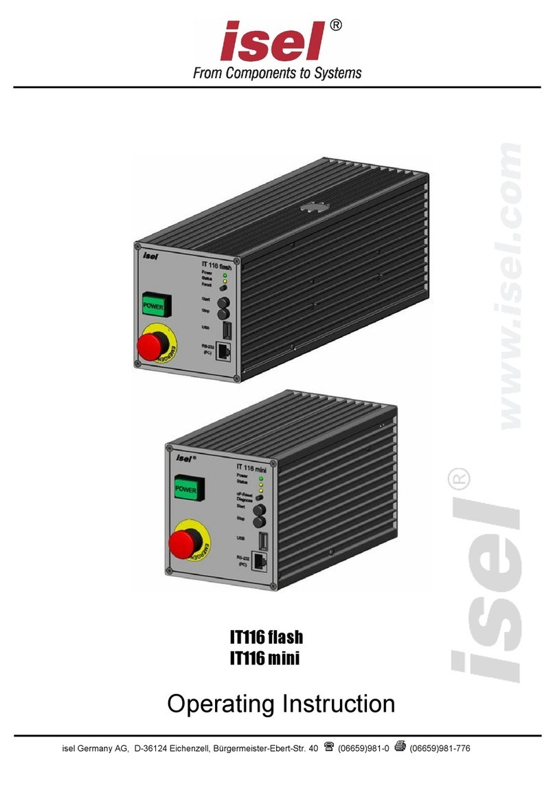
Isel MC1 Series User manual

isel Germany AG, D-36124 Eichenzell, Bürgermeister-Ebert-Str. 40 (06659)981-0 (06659)981-776
1-axis-controller MC1 series
MC1-10
MC1-20
MC1-30
MC1-40
Operating Instruction

1-axis-controller MC1: Operating instruction
Page - 2
Table of contents
1About this manual ............................................................................................................................... 4
2Controller types................................................................................................................................... 7
3Technical data...................................................................................................................................... 8
3.1 Technical data of series .........................................................................................................8
3.2 Technical data of the controller and power amplifier ...........................................................10
3.2.1 1-axis-controller MC1-10 10
3.2.2 1-axis-controller MC1-20 10
3.2.3 1-axis-controller MC1-30 11
3.2.4 1-axis-controller MC1-40 11
4Type independent hardware description of the MC1 series ......................................................... 12
4.1 Description of the base board for all types...........................................................................12
4.1.1 Base board pin assignment 13
4.1.2 Base board jumper settings 14
4.2 Control display (MC1-10, MC1-20, MC1-40)........................................................................15
4.3 Binary user input wiring........................................................................................................16
4.4 Binary user output wiring......................................................................................................16
5Hardware description MC1-10.......................................................................................................... 17
5.1 Overview...............................................................................................................................17
5.2 Pin assignment.....................................................................................................................17
6Hardware description MC1-20.......................................................................................................... 19
6.1 Overview...............................................................................................................................19
6.2 Pin assignment.....................................................................................................................19
7Hardware description MC1-30.......................................................................................................... 21
7.1 Overview...............................................................................................................................21
7.2 Pin assignment.....................................................................................................................21
8Hardwarebeschreibung MC1-40....................................................................................................... 23
8.1 Overview...............................................................................................................................23
8.2 Pin assignment.....................................................................................................................23
9Operation modes and operation...................................................................................................... 25
9.1 MC1 operation modes..........................................................................................................25
9.1.1 CNC mode 25
9.1.2 DNC mode 27
9.2 Operation (menu driven) ......................................................................................................28
9.2.1 Menu PROGRAM: program driven (automatic mode) 30
9.2.2 Menu MANUAL: Manual operation (initial operation mode) 32

1-axis-controller MC1: Operating instruction
Page - 3
9.2.3 Menu SETUP: Initial operation of motor power amplifier IMDxx / control options 45
10 Software .......................................................................................................................................... 49
10.1 Initial operation and parameterization power amplifiers IMDxx ...........................................49
10.1.1 Installing setup programs 49
10.1.2 Starting setup software and serial connection 50
10.2 PALPC: User programming for CNC mode and download..................................................54
10.2.1 Install programming software PALPC.exe 54
10.2.2 User programming for CNC mode and download 55
11 Troubleshooting............................................................................................................................. 61
12 EC Declaration of Conformity ....................................................................................................... 62
13 Bibliography.................................................................................................................................... 64
14 Index ................................................................................................................................................ 64

1-axis-controller MC1: Operating instruction
Seite - 4
1 About this manual
All information, technical data and dimensions contained in this booklet correspond to the technical state
at the moment of publication. However, possible misprints or mistakes cannot be ruled out. We will
appreciate all suggestions for improvement and error notes.
We would like to point out that all used software and hardware names of the respective companies
generally are subject to protection by brand, trademark and patent law.
All rights reserved. It is prohibited to process, duplicate or reproduce this booklet partially or on the whole
in any form (print, copy, or other procedure) without written permission of isel Germany AG.
This booklet has been translated from the original German version into English language. It does not lay
claim to completeness nor flawlessness. In case of doubt the German original has validity.
isel controllers are concurrent with CE norms and marked accordingly. Commissioning of all other parts
or components, for which CE safety regulations apply, is prohibited until all respective requests are met.
isel Germany AG as the manufacturer cannot take over guarantee if you change the controller in any
way.
The EMC test is valid only for the controllers original configuration ex works, i.e. the delivery state.
Manufacturer: isel Germany AG
Bürgermeister-Ebert-Straße 40
D-36124 Eichenzell
Tel.: (06659) 981-0
Fax: (06659) 981-776
http://www.isel.com
Part-No.: 970381 BE518
Revisions
Date of
change
Reason for change
Changed by
A
08/01/2014
Serial number
RL
07/2014
First print

1-axis-controller MC1: Operating instruction
Page - 5
Safety symbols
Attention
This symbol signalizes that there is danger for persons life and health.
Danger
This symbol signalizes that there is danger for material, machine and
environment.
Information
This symbol signalizes important information.
Safety instructions
The 1-axis-controllers MC1-10, MC1-20, MC1-30 and MC1-40 are designed to
current technical and recognized rules.
The device may only be used if it is in correct condition. Any faults have to be
eliminated immediately. Neither children nor non-authorized persons are allowed to
put the device into operation.
The device may only be used for the intended use: control of a linear or rotational
axis with brushed (MC1-10), brushless (MC1-20) DC servo motors or 3-phase
stepper motors (MC1-30) up to 500 W and integrated incremental measurement
system (encoder) in CNC or DNC mode.
All work with the 1-axis controller MC1-xx, especially initial operation, installation as
well as external wiring must be executed by authorized personal regarding
electrical industry rules and accident prevention regulations.
Assembly and use of operating material has to be according to machine directive
2006/42/EC resp. Low voltage directive 2006/95/EC. In case of in proper use even
the observation the respective rules and standards does not protect against
physical damages and damage to property.
Ambient temperature: +5°C to +40°C
Storage temperature: –25°C to +70°C
Pay attention that there is enough free zone on the louvers for air circulation.
Ignoring this fact causes overheat and potential defect of the controller.
Do not expose the device to high humidity or high vibrations.
Please take care of the instruction manual. Be sure that all users know the
instructions.
Ignoring the instruction manual can lead to damage, heavy physical damage or to
death.

1-axis-controller MC1: Operating instruction
Page - 6
Warning! High earth leakage current (ground discharge current,
protection conductor current). Before connecting to the AC supply
network, it is necessarily required an additional protective grounding.
Before connecting the CNC controller to the AC supply network, an
additional protective grounding (cross section: 2.5 mm2or 4 mm2, see
below) has to be connected! Before the electrical start-op of the controllers
a protective grounding of 2.5 mm2(protected installation) or a protective
conductor of 4 mm2(unprotected installation) has to be connected durably
to the marked clamping point at the back of the housing where the
cross section of the protective grounding shall not be less than 10 mm2
copper or 16 mm2aluminum has (e.g. electrical distribution of the
building). Please instruct an electrician with these implementation. When
using the Residual Current circuit Device (RCD) for line fuses/fault current
delimitation: Do not use an RCD with AC characteristics. Using a
frequency inverter and choppered power stages in the power units may
cause superimposed AC fault units with pulsating direct current and direct
current apart from AC fault currents. Please consult your electrician.
The term leakage is understood here as grounding discharge current.
This is defined in the standard EN 60204-1:2006 section 8.2.8, note 1
If the CNC machine (ideal) is set up isolated from the reference
potential, the grounding discharge current is equal to the protective
grounding stream.

1-axis-controller MC1: Operating instruction
Page - 7
2 Controller types
The 1-axis-controllers of series MC1-xx are compact desk devices for connection to the 115VAC /
230VAC public power supply net (50/60Hz).
All controllers are free programmable and destined for the use of linear or rotational axis with different
motor types.
The MC1-xx series comprises the following controller types:
type
motor
power amplifier
MC1-10
Part-No.: 381518 0010
brushed isel - DC-servo-motors (BB-DC)
IMD-10
MC1-20
Part-No.: 381518 0020
brushless isel - DC-servo-motors (BL-DC)
IMD-20
MC1-30
(in preparation)
Part-No.: 381518 0030
isel - 3-phase-stepper-motors
IMD-30
MC1-40
Part-No.: 381518 0040
brushless isel - DC-servo-motors (EC, BL-DC-310V)
IMD-40
All 1-axis-controller have to be used only with the compatible motor type.
Please read this operation instruction manual carefully before first use of the controller therewith you can:
•Work safely, fast and effective
•Keep away danger from persons
•Use all the power and features of the controller.

1-axis-controller MC1: Operating instruction
Page - 8
3 Technical data
3.1 Technical data of series
Case dimensions: 204mm (L) x 150mm (W) x 300mm (H)
(without the holder for motor cable)
Weight: 6550 g
Safety class: IP20
Power supply: 230 VAC, 50 Hz, fuse: 4 A
115 VAC, 60 Hz, fuse: 6 A
Power consumption: power supply 48VDC: max. 500W,
power supply 24VDC: max. 2,5A (60W)
power supply 24VDC controller internally load 0,5 A (12W)
i.e. there is maximum 2A for external wiring of user In-/Outputs
(without a connected motor brake)
Ambient temperature: 5°C to +40°C
Storage temperature: -25°C to +70°C
Humidity: max. 95%
STOP category: 0 according to EN 60204-1:2006, 9.2.2
Operation modes:
standard operation mode: CNC-mode (Stand alone, program download in flash memory)
additional operation mode: DNC-mode (optional operation with PC)
User control interface:
LC display 4 lines x 20 symbols, english character set (alphanumerical, dot matrix 5x7)
foil keyboard: 4 keys F1 to F4 for softkey control, Start, Stop, Enter, ESC
Binary inputs:
external program-start on E1.1 = Input 1 on controller back side
external program-stop on E1.2 = Input 2 on controller back side
positive / negative end switch, reference switch (for micro switch or initiator –opener means n.c.)
8 free user inputs (24VDC, optically isolated; load of the internal 24VDC/60W-power supply with
12,5 mA per input if high active input connection) with LED bargraph
analog input (future extension, not available in this version)

1-axis-controller MC1: Operating instruction
Page - 9
Binary outputs:
motor brake
8 free user relay outputs (24VDC / max. 700 mA per output) with LED bargraph
1,9 A maximum load of the internal 24V/60W power supply if all 8 outputs set to high (230 mA per
output)
The user is responsible for dimensioning the current load of the
binary outputs.
PWM output (future extension, not available in this version)
Download memory for PALPC user programs (CNC mode)
Flash memory for about 650 commands and separate memory for LCD text output (ca. 100 text
lines by 20 ASCII characters)
Communication interfaces:
RS232 interface for program download and parameterization of the power amplifier
USB interface (future extension, not available in this version)
CANopen interface (future extension, not available in this version)
Programming software:
PALPC 2.1 for programming in CNC mode, program download
ProNC / Remote for operation in DNC mode
Scope of delivery:
1-axis controller MC1-xx as desk device with integrated power amplifier IMD-xx
Main cable (protection contact plug, IEC-60320 power connector)
RS232 communication cable: PC-side: 9 pin Sub-D jack
Controller side: RJ45 plug
Installation CD PAL-PC 2.1
Installation CD isel-CAN-CNC-control with initial operation program
Operation instruction manual in printed form

1-axis-controller MC1: Operating instruction
Page - 10
3.2 Technical data of the controller and power amplifier
3.2.1 1-axis-controller MC1-10
Controller:
Controller for linear- or rotational axis with brushed DC servo motor
Power supply for intermediate circuit: 48VDC / 500W with PFC
Embedded controller MCF52223 with flash memory for firmware update and download of user
programs (firmware update ex factory possible)
Back side connector (8 pin remote plug) for integration in higher ranked security circuit
Protection against short circuit, over- resp. under voltage, over temperature
Back side connector for external Start- resp. Stop button or signal (PLC control)
Back side connector for PWM output and analog input (optional)
Back side USB jack (future extension, load user programs from memory stick, not available
in this version)
Initial operation software:
Parameterization of the motor power amplifier IMD10 (gear factor, encoder resolution, current-
speed- and position control) over serial interface RS232-PC (RJ45-connector); PC based initial
operation software ”DCSetup.exe”
3.2.2 1-axis-controller MC1-20
Controller:
Controller for linear- or rotational axis with brushless DC servo motor
Power supply for intermediate circuit: 48VDC / 500W with PFC
Motor current up to 12 A (digital current regulation)
Embedded controller MCF52223 with flash memory for firmware update and download of user
programs (firmware update ex factory possible)
Back side connector (8 pin remote plug) for integration in higher ranked security circuit
Protection against short circuit, over- resp. under voltage, over temperature
Back side connector for external Start- resp. Stop button or signal (PLC control)
Back side connector for PWM output and analog input (optional)
Back side USB jack (future extension, load user programs from memory stick, not available
in this version)
Initial operation software:
Parameterization of the motor power amplifier IMD20 (gear factor, encoder resolution, current-
speed-, position control) over serial interface RS232-PC (RJ45-connector); PC based initial
operation software ”ACSetup.exe”

1-axis-controller MC1: Operating instruction
Page - 11
3.2.3 1-axis-controller MC1-30
Controller:
Controller for linear- or rotational axis with 3 phase stepper motor
Power supply for intermediate circuit: 48VDC / 500W with PFC
Motor current up to 10 A (digital current regulation)
Embedded controller MCF52223 with flash memory for firmware update and download of user
programs (firmware update ex factory possible)
Back side connector (8 pin remote plug) for integration in higher ranked security circuit
Protection against short circuit, over- resp. under voltage, over temperature
Back side connector for external Start- resp. Stop button or signal (PLC control)
Back side connector for PWM output and analog input (optional)
Back side USB jack (future extension, load user programs from memory stick, not available
in this version)
Initial operation software:
Parameterization of the motor power amplifier IMD30 (gear factor, encoder resolution, current-
speed-, position control) over serial interface RS232-PC (RJ45-connector); PC based initial
operation software ”StepSetup.exe”
3.2.4 1-axis-controller MC1-40
Controller:
Controller for linear- or rotational axis with brushless DC servo motor (EC, BLDC 310
Power supply: 230V AC single-phase, intermediate circuit: 310VDC
Motor current up to 6.5 A (digital current regulation)
Embedded controller MCF52223 with flash memory for firmware update and download of user
programs (firmware update ex factory possible)
Back side connector (8 pin remote plug) for integration in higher ranked security circuit
Protection against short circuit, over- resp. under voltage, over temperature
Back side connector for external Start- resp. Stop button or signal (PLC control)
Back side connector for PWM output and analog input (optional)
Back side USB jack (future extension, load user programs from memory stick, not available
in this version)
Initial operation software:
Parameterization of the motor power amplifier IMD40 (gear factor, encoder resolution, current-
speed-, position control) over serial interface RS232-PC (RJ45-connector); PC based initial operation
software ”ACSetup.exe

1-axis-controller MC1: Operating instruction
Page - 12
4 Type independent hardware description of the MC1 series
Image 1: front view (for example MC1-10)
4.1 Description of the base board for all types
The 1-axis-controller MC1 series base board consists of: user I/Os, embedded controller with LCD and
keyboard interface, two serial interfaces (RS232 asynchronous to PC resp. Power amplifier) and security
circuit functions (Emergency stop circuit). The base board is mounted in all controller types.
Image 2: base board layout
JP3
X13
JP2
X6
C1
C2
JP4

1-axis-controller MC1: Operating instruction
Page - 13
4.1.1 Base board pin assignment
C1: RS-232-connector to motor amplifier
1 - RxD Receive Data
2 - TxD Transmit Data
3 - GND
C2: Connection of POWER-button, FAULT-signal, Emergency-stop-button in the case front
1 - GND GND
2 - 24VDC operating voltage from 24VDC power supply unit
3 - Emergency stop Ch1 (11) Emergency stop switch
4 - Emergency stop Ch2 (12) Emergency stop switch
5 - Emergency stop Ch2 (21) Emergency stop switch
6 - Emergency stop Ch2 (22) Emergency stop switch
7 - Error Out FAULT-notification
8 - GND FAULT-notification GND
9 - Power (13) POWER-button
10 - Power (14) POWER-button
11 - Power lamp (cathode) POWER lamp
12 - Power lamp (anode) POWER lamp
X6: Power switch (primary side 500W power supply unit for motor amplifier operating voltage)
1 - L1
2 - L1’
3 - N
4 - N’
X13: Connector for foil keyboard
1 - Start key (3) P0.7
2 - Start key (4) GND
3 - Stop key (3) P0.6
4 - Stop key (4) GND
5 - Enter key (3) P0.5
6 - Enter key (4) GND
7 - Esc key (3) P0.4
8 - Esc key (4) GND
9 - F1 key (3) P0.3
10 - F1 key (4) GND
11 - F2 key (3) P0.2
12 - F2 key (4) GND
13 - F3 key (3) P0.1
14 - F3 key (4) GND
15 - F4 key (3) P0.0
16 - F4 key (4) GND

1-axis-controller MC1: Operating instruction
Page - 14
4.1.2 Base board jumper settings
JP2: LC display connection (I2C-Bus)
1 - +5V
2 - SDA data
3 - SCL step
4 - GND
JP3: Motor amplifier connection
1 - Analog IN+ type dependent used
2 - Analog IN- type dependent used
3 - Digital GND type dependent used
4 - Analog GND type dependent used
5 - Enable enable motor amplifier
6 - Enable enable motor amplifier
7 - Ready IN statically 24VDC
8 - Ready OUT FAULT signal
9 - Homing bridge end switch during reference run
10 - Homing bridge end switch during reference run
11 - Limit IN control current circuit (emergency stop circuit)
12 - Limit OUT control current circuit (emergency stop circuit)
13 - Logic 24V 24VDC operation voltage
14 - Logic 24V 24VDC operation voltage
15 - Logic GND reference operation voltage
16 - Logic GND reference operation voltage
JP4: Settings for switch on operation voltage of the power amplifier (internal/external)
Pin 1, 2bridged: Power On internal: front POWER button will be used
Pin 2, 3bridged: Power On external: contacts 7 and 8 of the Remote-connector will be used

1-axis-controller MC1: Operating instruction
Page - 15
4.2 Control display (MC1-10, MC1-20, MC1-40)
The controller MC1 has several control displays. These are:
Controller-front side:
FAULT- lamp (red) -> error in motor power amplifier; no ready signal (READY, 1-aktive = HIGH)
will be generated from the motor power amplifier
POWER-lamp (green) is on -> motor power amplifier und DC-servo motor powered
Controller-back side:
LEDs for signaling active outputs = 1-active / HIGH (yellow LED on)
LEDs for signaling active input = 1-active / HIGH (green LED on)
LEDs for signaling state of the power amplifier
(blink codes look at IMD10-Manual /1/ or IMD20-Manual /2/)
LEDs for signaling state of power supply:
5V –logic voltage motor power amplifier
24VDC –80 VDC –motor voltage power amplifier
24V –controller internal operation voltage for base board and user I/O
LEDs for signaling active
outputs
LEDs for signaling active
input
5V –logic voltage motor
power amplifier
24VDC –80 VDC –motor voltage
power amplifier
24V –controller internal
operation voltage:
Input: LED green
Output: LED yellow
LEDs for signaling state of the power amplifier
(device state)

1-axis-controller MC1: Operating instruction
Page - 16
4.3 Binary user input wiring
The binary user inputs 1 - 8 of the MC1 are realized using 24V-DC process voltage.
The 24VDC reference potential is used from the controller internal 24VDC power supply unit. (no galvanic
separation !).
Do not short 24VDC reference potential of the controller with GND or
case ground.
The binary user inputs 1 –8 must be wired
as shown opposite. (InX means Input 1 to 8).
The load of the controller internal 24V/60W
power supply unit amounts on 1-active state
12,5 mA per input.
4.4 Binary user output wiring
The binary user outputs of the MC1 switch 24VDC process voltage. The switched 24VDC reference
potential for every external load will be used from the internal 24VDC power supply unit (no galvanic
separation!).
Do not short 24VDC reference potential of the controller with GND or
case ground.
When using inductance, an free-wheeling diode is necessarily.
If you have pushed the emergency stop switch all states of the binary
user outputs will be maintained and not reset!
The user is responsible for dimensioning the current load of
the binary outputs.
The binary user output 1 –output 8 must be
wired as shown opposite. (Out X means
output 1 to 8).
The relay outputs output 1 –output 8 can be
rated with 700 mA per output.
If all outputs are switched (1-active) the
maximum load of the internal 24VDC power
supply unit is 1,9 A (ca. 230mA per output)

1-axis-controller MC1: Operating instruction
Page - 17
5 Hardware description MC1-10
5.1 Overview
1-axis-controller MC1-10 contains the following modules:
Base board with user I/O, embedded controller with LCD- and keyboard interface, 2 serial
interfaces RS232, asynchronous to PC resp. motor power amplifier IMD10, security circuit
functions (emergency stop circuit)
Motor power amplifier IMD10
Power supply unit 48VDC/500W, power supply unit 24VDC/60W
Net input module with main switch, net filter and fuses
4 part mechanical chassis (ground plate, front side, back side, covering hood)
Front side with LC-display, foil keyboard (soft keys: Stop, Start, ESC and ENTER)
Back side with motor cable connector, power supply line, remote connector, PC connector
(RS232), connectors for binary inputs and outputs
5.2 Pin assignment
Image 3: Back side view controller MC1-10

1-axis-controller MC1: Operating instruction
Page - 18
5-pin motor power plug:
Pin (left right)
Signal
Description
1
2
3
4
5
1
2
PE
Brake
Brake_GND
Motor line 1 (brown/green)
Motor line 2 (white/yellow)
Protective ground
Output motor brake
GND 24V (reference motor brake)
8-pin remote plug:
1 - Potential free contact - output
2 - Potential free contact - output
3 - Emergency stop external Ch2
4 - Emergency stop external Ch2
5 - Emergency stop external Ch1
6 - Emergency stop external Ch1
7 - Power On external - input
8 - Power On external - input
Contacts 1 and 2 will be bridged from the base board as far as the
operation voltage of the motor power amplifier IMD10 is switched on.
Contacts 7 and 8 must be bridged to switch on operation voltage for motor
power amplifier IMD10 (condition is that pin 2 and 3 of jumper JP4 are
bridged to enable PowerOn external mode).
4-pin connector:
1 - PWM-signal (output), 1 kHz
2 - 5V logic voltage
3 - Analog signal (output)
4 - GND logic voltage
15-pin SubD-connector for motor signals:
Pin
Signal
Description
1
2
3
4
5
6
7
8
9
10
11
12
13
14
15
VCC
/ENC_Z
/ENC_B
/ENC_A
24V
LIMIT_SW1
GND_24V
DGND
ENC_Z
ENC_B
ENC_A
REF_SW
LIMIT_SW2
Digital +5V
Encoder line /Z
Encoder line /B
Encoder line /A
Logic 24V
End switch 1
Logic GND
Digital GND
Encoder line Z
Encoder line B
Encoder line A
Reference switch
End switch 2

1-axis-controller MC1: Operating instruction
Page - 19
6 Hardware description MC1-20
6.1 Overview
1-axis-controller MC1-20 contains the following modules:
Base board with user I/O, embedded controller with LCD- and keyboard interface, 2 serial
interfaces RS232, asynchronous to PC resp. motor power amplifier IMD20, security circuit
functions (emergency stop circuit)
Motor power amplifier IMD20
Power supply unit 48VDC/500W, power supply unit 24VDC/60W
Net input module with main switch, net filter and fuses
4 part mechanical chassis (ground plate, front side, back side, covering hood)
Front side with LC-display, foil keyboard (soft keys: Stop, Start, ESC and ENTER)
Back side with motor cable connector, power supply line, remote connector, PC connector
(RS232), connectors for binary inputs and outputs
6.2 Pin assignment
Image 4: Back side view controller MC1-20

1-axis-controller MC1: Operating instruction
Page - 20
6-pin motor power plug:
Pin (left right)
Signal
Description
1
2
3
4
5
6
3
2
1
PE
Brake
Brake_GND
Motor line 3
Motor line 2
Motor line 1
Protective ground
Output motor brake
GND 24V (reference motor brake)
8-pin remote plug:
1 - Potential free contact - output
2 - Potential free contact - output
3 - Emergency stop external Ch2
4 - Emergency stop external Ch2
5 - Emergency stop external Ch1
6 - Emergency stop external Ch1
7 - Power On external - input
8 - Power On external - input
Contacts 1 and 2 will be bridged from the base board as far as the
operation voltage of the motor power amplifier IMD20 is switched on.
Contacts 7 and 8 must be bridged to switch on operation voltage for motor
power amplifier IMD20 (condition is that pin 2 and 3 of jumper JP4 are
bridged to enable PowerOn external mode).
4-pin connector:
1 - PWM-signal (output), 1 kHz
2 - 5V logic voltage
3 - Analog signal (output)
4 - GND logic voltage
15-pin SubD-connector for motor signals:
Pin
Signal
Description
1
2
3
4
5
6
7
8
9
10
11
12
13
14
15
HALL_A_IN
VCC
/ENC_Z
/ENC_B
/ENC_A
24V
LIMIT_SW1
GND_24V
HALL_B_IN
DGND
ENC_Z
ENC_B
ENC_A
HALL_C_IN
LIMIT_SW2
Hall signal A
Digital +5V
Encoder line /Z
Encoder line /B
Encoder line /A
Logic 24V
End switch 1
Logic GND
Hall signal B
Digital GND
Encoder line Z
Encoder line B
Encoder line A
Hall signal C
End switch 2
This manual suits for next models
4
Table of contents
Other Isel Controllers manuals
Popular Controllers manuals by other brands

Balmar
Balmar CENTERFIELDER II Installation & operator's manual

oventrop
oventrop Aktor M ST/2P L operating instructions

Pentair
Pentair Goyen IS Series Products Installation Instructions

Exodraft
Exodraft EBC10 Instructions for fitting, installation and operation

TLV
TLV SC-F70 operating instructions

Amazone
Amazone EasySet 2 operating manual