Software Bisque Paramount ME II User manual

Paramount ME II, Paramount MX,
Paramount MX+ and Paramount MYT
Homing Sensor and Homing Sensor Cable
Troubleshooting and Wiring Instructions
Revision 3, January 2017
© 2014 Software Bisque, Inc. All rights reserved.

Table of Contents
Troubleshooting Homing Sensors ............................................................................................................... 3
Replacing a Homing Sensor......................................................................................................................... 3
Removing Homing Sensor Cable ................................................................................................................. 4
Step 1: Remove the Worm Block Covers................................................................................................. 4
Step 2: Unplugging the Sensor Electronics.............................................................................................. 7
Step 3: Removing the Existing Cable ....................................................................................................... 8
Removing the Electronics Box..................................................................................................................... 9
Installing the Replacement Homing Sensor Cable ...................................................................................... 9
Step 1: Installing the Right Ascension Side of the Homing Sensor Cable .............................................. 11
Step 2: Installing the Declination Side of the Homing Sensor Cable ..................................................... 11
Replacing Electronics Box ......................................................................................................................... 12
Troubleshooting Homing Sensors
Typically, when homing is not working correctly, the homing sensors rarely fail and it is one of these
three things:
1. The homing sensor cable has been pinched
a. Using the instructions and diagrams below in Removing Homing Sensor Cable to remove
the worm block cover of the axis that is not homing and look for a pinched cable. This
can happen if the worm block cover is replaced and the homing sensor isn’t moved out
of the way.
2. The homing sensor has grease in it
a. If too much grease has been put on the gear, then the extra grease can be transferred
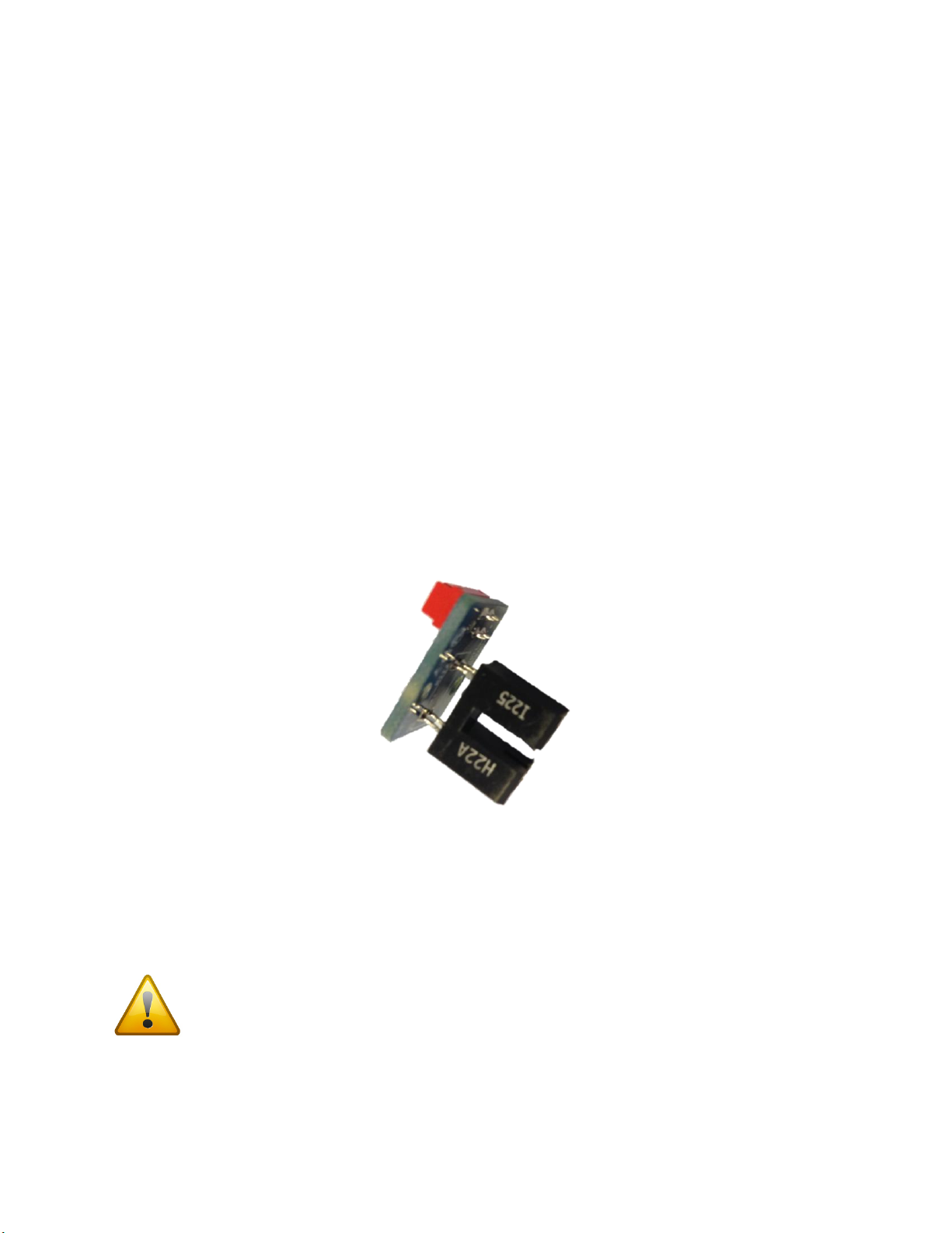
from the gear to the homing sensor during use of the mount. See Figure 8 for what the
homing sensor looks like. Follow the steps below in Replacing a Homing Sensor to get
access to the sensor. The sensor cable can stay plugged in to help grab the sensor to
both uninstall and to install. Inspect the sensor for any grease in between the black “U”
(see Figure 1).
3. The homing sensor has been damaged
a. Follow the steps from #2 above and make sure the sensor is not damaged or bent in any
way.
Figure 1: Sensor PCB
Replacing a Homing Sensor
To just replace a homing sensor and not the cable, follow Step 1: Remove the Worm Block Covers and
Step 2: Unplugging the Sensor Electronics below. These two steps give you access to the homing sensor.
Tape over the hole that gives access to the cables going in to the mount so screws cannot
fall in to the tube for either axis.
There are two screws that hold in the homing sensor (see Figure 8). Use a flat end 1/16” allen key to
remove the two 4-40 button head cap screws and free the sensor. Take care not to drop any screws in
to either tube when removing sensor. The sensor only fits one way in to the cover so note that the red
connector to plug in to is on top for ease of replacing.
Reverse these directions to replace with new homing sensor. Make sure all the slack from the cable is
pushed back in to the hole in the tube before replacing the cover.
Be careful to not pinch cables when replacing the cover or tightening screws! Pinched
cables can cause electronic issues or erratic behavior.
Removing Homing Sensor Cable
Step 1: Remove the Worm Block Covers
Remove both worm block covers so that homing sensor cables can be unplugged.
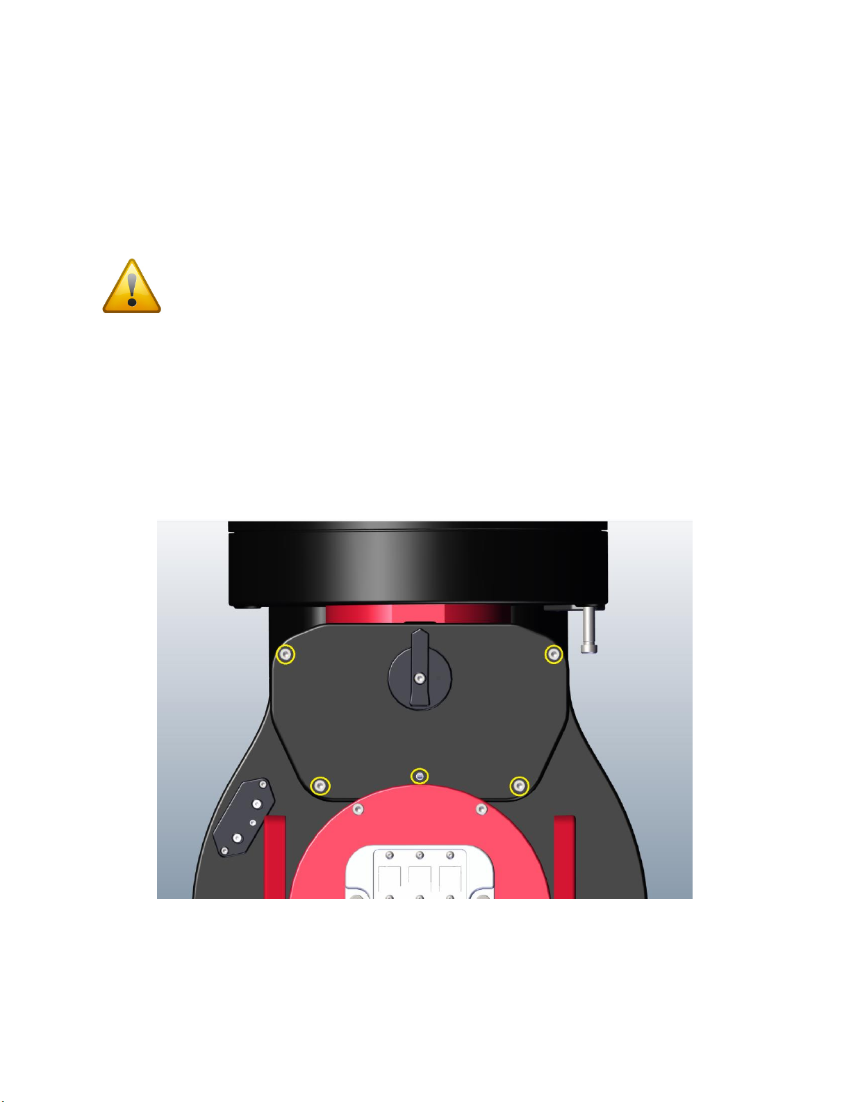
The worm block cover is attached to the mount with five 10-32 socket head cap screws (SHCS), see
Figure 2. Remove each using a 5/32-inch hex wrench. The cover should come off with little to no force,
however, sometimes the standoffs that align the cover to the mount body can bind. A light “tap” with
the palm of your hand will release the cover.
Figure 2: Five worm block cover screws to be removed for Paramount ME II.
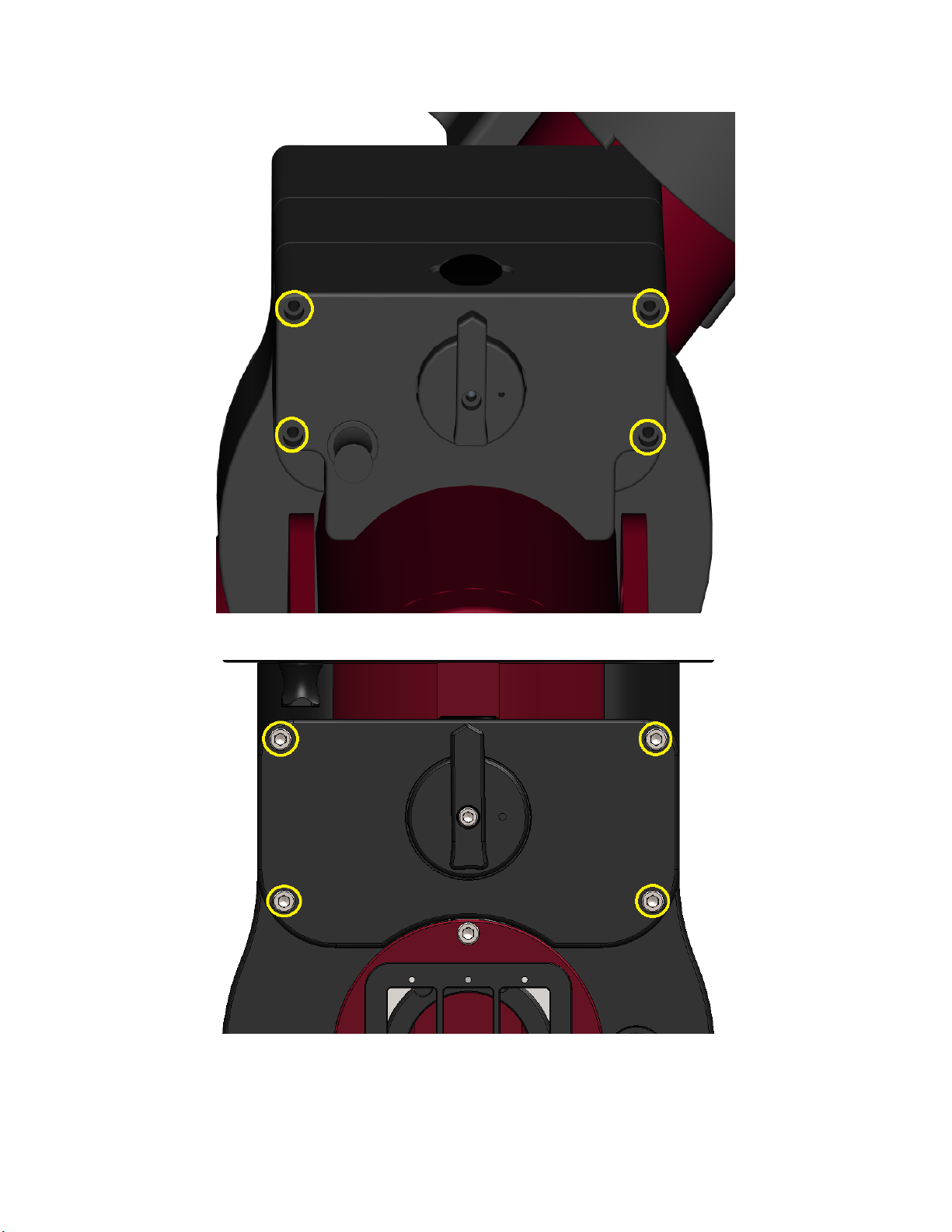
Figure 3: Four worm block cover screws to be removed for Paramount MX/MX+
Figure 4: Four worm block cover screws to be removed for Paramount MYT
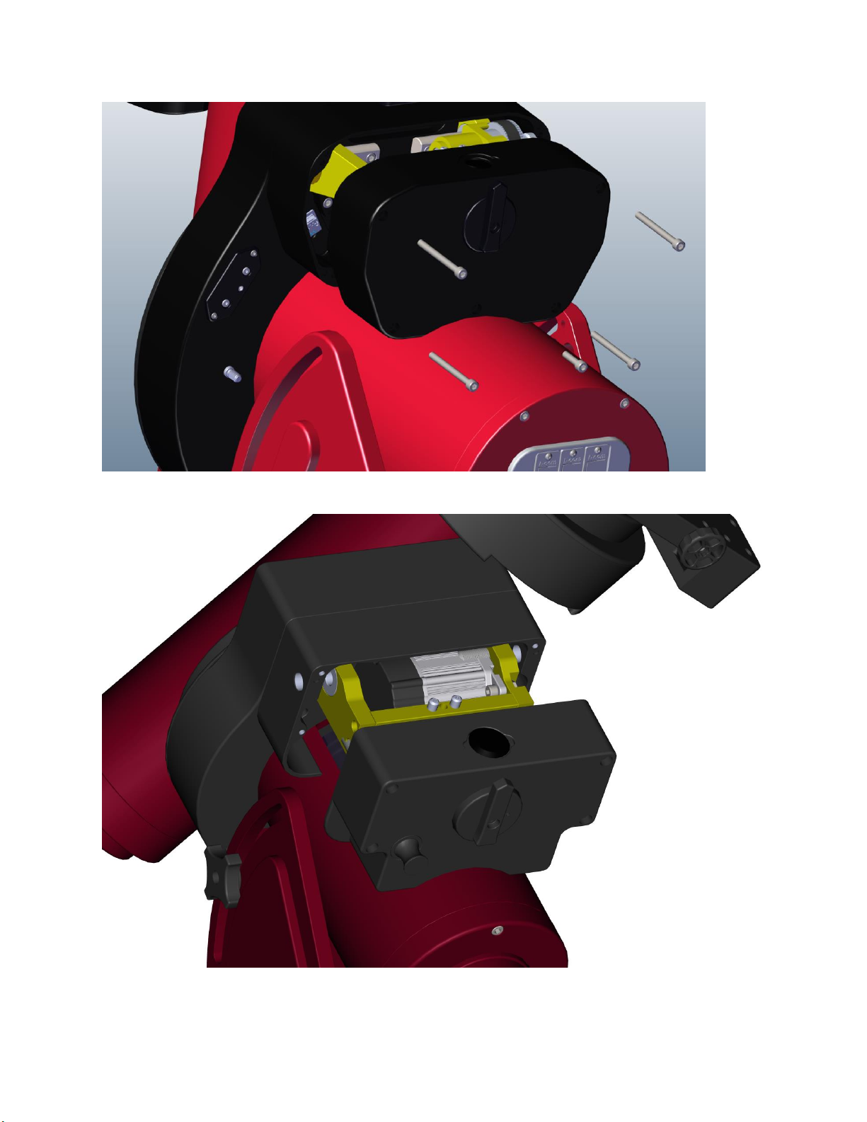
Figure 5: Removing cover from Paramount ME II (note that the above screw sizes are different and may not look to scale)
Figure 6: Removing cover from Paramount MX+.
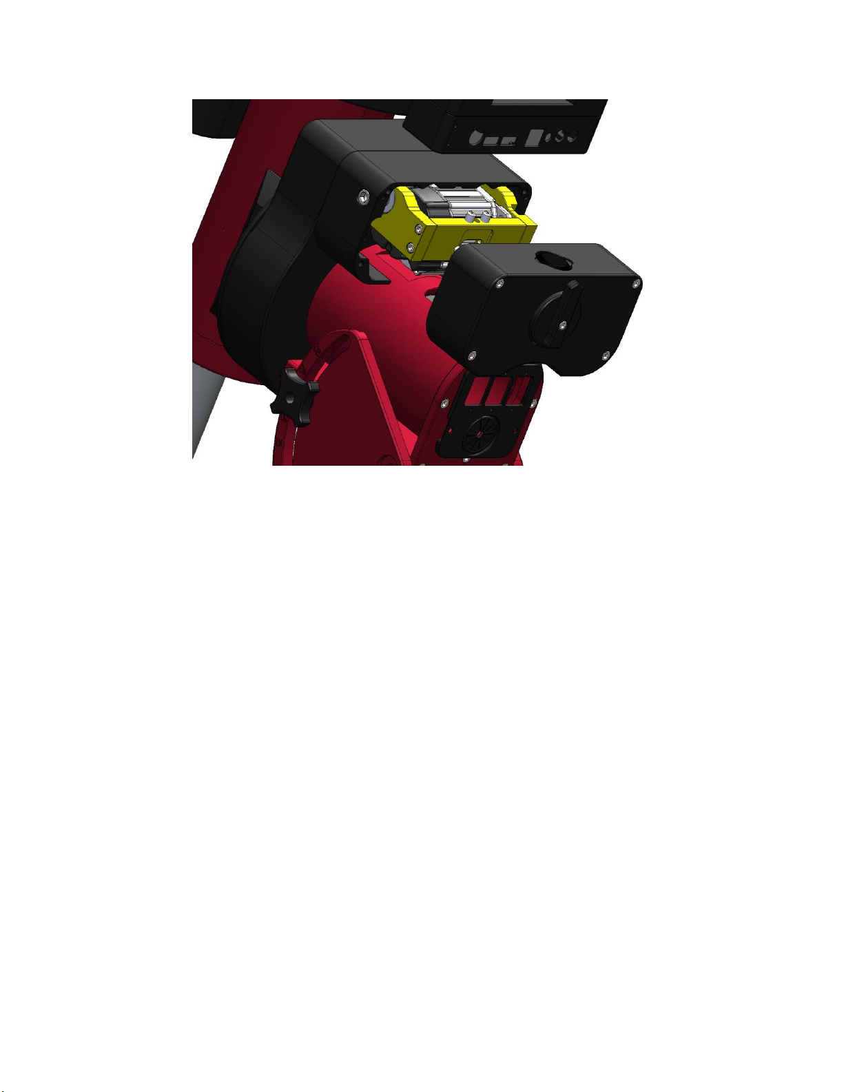
Figure 7: Removing cover from Paramount MYT
Step 2: Unplugging the Sensor Electronics
Figure 8 shows the homing sensor cable in the mount. Gently pull the connector straight out, away from
the mount to unplug it. Make a note of which side the long tab is on so that the replacement cable can
be plugged in the same way.

Figure 8: Declination half of the sensor cable.
Unplug homing sensors in both the right ascension and declination axes.
Step 3: Removing the Existing Cable
For the right ascension axis, feed the homing sensor down through the hole in the right ascension tube
then pull the remaining cable out of the mount from the void left by removing the Electronics Box (see
Removing the Electronics Box).
For the declination axis, remove the rear cover (Figure 10) by unscrewing the two thumb screws. Also
remove the two 8-32 SHCS with a 7/64 hex wrench from the declination axis hole cover (see Figure 9,
screws highlighted in blue).
Next, slowly rotate the declination axis the homing sensor cable is visible, then gently grasp and pull it
down through the declination tube axis hole. You may have to rotate the declination axis slightly while
pulling the cable out of the Electronics Box end in order to prevent the sensor connector from catching
on the other cables in the declination tube.
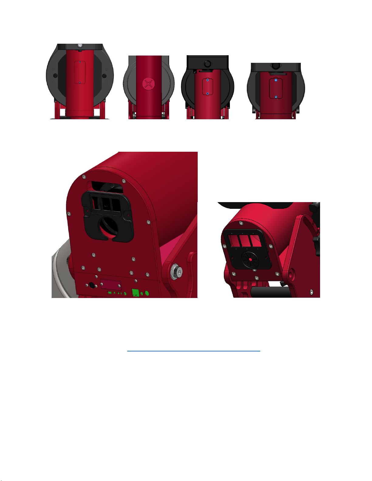
Figure 9: Declination axis hole cover with screws.
(From left to right Paramount ME II, Paramount MX, Paramount MX+, Paramount MYT)
Figure 10: Right ascension rear cover.
Removing the Electronics Box
Please refer to this document: http://www.bisque.com/sc/media/p/63292.aspx. It also explains the
purpose of each cable plugged in to the MSK 5000 board. Depending on how small and nimble your
hands are, it is probably easiest to unplug all of the cables and completely remove the Electronic Box
before removing and replacing the homing sensor cable.
Installing the Replacement Homing Sensor Cable
The Paramount Accessory Kit includes a long zip tie looped at one end. This tie is especially helpful to
install the replacement cable. Use a short piece of electrical tape to attach the connector to the looped
end of the zip tie.

The small rubber-banded loop in right ascension sensor cable shown in Figure 8 is intended to provide
strain relief. This loop can also be used to attach the zip. The pointed, non-looped end of the zip tie
should be fed up through the mount, to the sensor connectors. There are two holes in the base of the
right ascension axis for both the Paramount ME II and Paramount MX/MX+ (Figure 11). The right
ascension sensor cable must be fed through the hole, located toward the center of the mount and is
circled in blue in Figure 11 for the Paramount ME II and Paramount MX/MX+. For the Paramount MYT
there is only one hole in the RA base used for all cables coming from the electronics box, see Figure 12.
Figure 11: RA base, RA wiring hole (Paramount ME II on the left, Paramount MX/MX+ on the right).
Figure 12: Paramount MYT RA base, cable wiring hole
Step 1: Installing the Right Ascension Side of the Homing Sensor Cable
The right ascension sensor has four wires colored either white, black, brown and red or brown, red,
orange and yellow. The colors don’t matter as much as the placement of the tab. Starting at the
Electronics Box, insert the zip tie with this half of the sensor cable attached up through the hole shown
in Figure 11 and guide the zip tie up to the hole in the RA tube where you pulled it from originally.
The shortest distance, and best practice, is to stay on the side of the right ascension shaft closest to the
hole in the right ascension tube. Gently pull the zip tie and sensor cable up through the mount until the
sensor cable can be plugged in. Remove the zip tie and plug in to the homing sensor. Remember, the
long tab on the connector goes on the right side.
You can now replace the right ascension worm block cover.
Be careful to not pinch cables when replacing the cover or tightening screws! Pinched
cables can cause electronic issues or erratic behavior.
Step 2: Installing the Declination Side of the Homing Sensor Cable
The declination sensor also has four wires, colored orange, yellow, green, and blue or green, blue,
purple, grey. Again, the colors don’t matter as much as the placement of the tab. As before, attach the
zip tie to the declination sensor cable.

This cable gets fed through the front hole in the right ascension base (circled in yellow in Figure 13), and
follows same route as the other cables in the right ascension shaft: into the declination tube and up,
around the declination shaft, finally to be fed up into the motor hole.
If you have trouble getting the zip tie to go around the declination shaft, then feed the zip tie partially
through the holes in the declination shaft while simultaneously rotating the declination axis by hand.
The most critical step in this process is to avoid feeding the sensor cable into any holes in center
declination shaft.
Figure 13: RA Base, Declination wiring hole (Paramount ME II on left, Paramount MX/MX+ on right).
Once you have fed the sensor cable through the motor hole and can plug it in to the homing sensor
(long tab from the connector on the right), the worm block cover can be replaced.
Be careful to not pinch cables when replacing the cover or tightening screws! Pinched cables
can cause electronic issues or erratic behavior.
Replacing Electronics Box
Refer to this document: http://www.bisque.com/sc/media/p/63292.aspx to plug all cables in and
replace the Electronics Box.
This manual suits for next models
2
Table of contents


