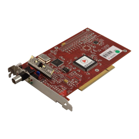
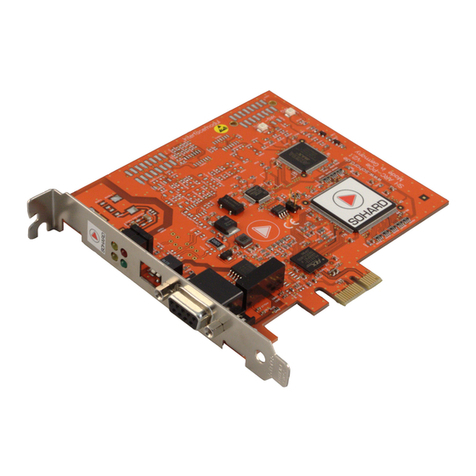
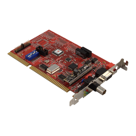
SOHARD SH ARC-PCMCIA User manual


Handbuch / Manual
2

Handbuch / Manual
Content
1 Sicherheitshinweise ..................................................................................5
1.1 Warnungen und Anweisungen.......................................................5
1.2 Installation.......................................................................................5
1.3 Elektromagnetische Verträglichkeit................................................5
1.4 Belüftung.........................................................................................5
1.5 Temperatur......................................................................................6
1.6 Umkonfiguration von Schnittstellenmodulen..................................6
2 Einleitung...................................................................................................6
3 Inbetriebnahme..........................................................................................6
3.1 Änderung von Busterminierung und Sendeleistung......................6
3.2 Zugriff..............................................................................................7
3.3Speicherbelegung............................................................................7
3.4 Einbau der Karte.............................................................................7
3.5 Gerätetreiber und alternative Zugriffsmöglichkeiten......................7
3.6 COM20022-Konfiguration...............................................................8
Beim Zugriff auf die empfangenen oder gesendeten Daten kann der
COM20022 sowohl im 8-Bit Modus (entspricht COM20020) als auch
im 16 Bit Modus[2] betrieben werden. LED-Anzeigen an dem
Netzwerk-Schnittstellen-Modul.............................................................8
3.7 LED-Anzeigen an dem Netzwerk-Schnittstellen-Modul.................9
4 ARCNET-Schnittstellen.............................................................................9
4.1 Koaxiale Schnittstelle (SH KOAX-PCMCIA)..................................9
4.2 RS-485/EIA-485-Schnittstelle (SH RS485-PCMCIA)....................9
4.3 RS485AC-Schnittstelle (SH RS485AC-M)...................................11
4.4 Twisted-Pair-Schnittstelle (SH TWP-PCMCIA)............................11
4.5 LWL-Schnittstellen (SH LWLSMA-PCMCIA, SH LWLST-
PCMCIA, SH LWLTOS-PCMCIA)......................................................12
5 Was tun bei Problemen?.........................................................................13
6 Safety Instructions...................................................................................15
6.1 Warnings and Instructions............................................................15
6.2 Installation.....................................................................................15
6.3 To ensure Electro-magnetic compatibility....................................15
6.4 Ventilation.....................................................................................15
6.5 Temperature..................................................................................15
6.6 Re-configuration of interface modules with modular devices......16
7 Introduction..............................................................................................16
8 Starting Up...............................................................................................16
8.1 Switching bus termination and transmission power.....................16
8.2 Access...........................................................................................16
8.3 Installation of the card...................................................................17
3

Handbuch / Manual
8.4 Device drivers and alternative access..........................................17
8.5 COM20022 Configuration.............................................................18
8.6 LED's on network-interface-module.............................................18
9ARCNET Interfaces..................................................................................19
9.1 Coaxial Interface (SH KOAX-PCMCIA)........................................19
9.2 RS-485/EIA-485 Interface (SH RS485-PCMCIA)........................19
9.3 RS485AC Interface (SH RS485AC-PCMCIA).............................20
9.4 Twisted pair Interface (SH TWP-PCMCIA)..................................21
9.5 Fiber Optic Interfaces (SH LWLSMA-PCMCIA, SH LWLST-
PCMCIA, SH LWLTOS-PCMCIA)......................................................21
10 Troubleshooting.....................................................................................22
11Technical Specifications.........................................................................23
11.2 CE Declaration of Conformity ....................................................25
11.3 Contact........................................................................................25
11.4 Warranty......................................................................................25
11.5 Support........................................................................................25
11.6 Order information........................................................................26
11.7 Literature.....................................................................................26
4

Handbuch / Manual
1 Sicherheitshinweise
Für eine sichere Verwendung und für die elektromagnetische
Verträglichkeit des Gerätes sind folgende Sicherheitshinweise bei der
Installation und dem Betrieb zu befolgen.
1.1 Warnungen und Anweisungen
Lesen Sie die Sicherheitshinweise vor der Inbetriebnahme des Gerätes.
Heben Sie diese Sicherheitshinweise gut auf und beachten Sie die
enthaltenen Warnungen und Anweisungen.
1.2 Installation
Das Gerät darf nur in industriellen Umgebungen verwendet werden. Es
darf nur in PCs mit Gehäusen gemäß EN 60950-1 eingebaut und
betrieben werden.
1.3 Elektromagnetische Verträglichkeit
a) An den ARCNET-Anschlüssen dürfen nur geschirmte Kabel mit
geschirmten Steckern angeschlossen werden.
b) Es dürfen nur Bitraten verwendet werden, die von SOHARD für das
gewählte Übertragungsverfahren spezifiziert sind.
c) Bei modularen Geräten dürfen nur originale Schnittstellenmodule von
SOHARD verwendet werden.
d) Das Gerät darf nur in PCs mit durchgehender Schirmung verwendet
werden.
Unbelegte Slots und Laufwerkeinschübe des PC-Gehäuses müssen mit
geeigneten Blenden verschlossen sein.
1.4 Belüftung
Das Gerät ist so zu montieren, dass beim Betrieb ausreichend Belüftung
vorhanden ist.
5

Handbuch / Manual
1.5 Temperatur
Das Gerät darf nicht außerhalb der angegebenen Temperaturbereiche
betrieben und gelagert werden.
1.6 Umkonfiguration von Schnittstellenmodulen
Das Gerät darf nur im ausgesteckten Zustand umkonfiguriert werden.
Bitte entnehmen Sie dem Handbuch weitere Hinweise zur Bedienung des
Geräts.
2 Einleitung
Die Geräte der Produktfamilie SH ARC-PCMCIA sind ARCNET-Adapter
für Rechner mit PCMCIA-Slot vom Typ 1. Als ARCNET-Controller kommt
der COM20022 [2] zum Einsatz.
Die Karte verfügt über einen 16 Bit breiten Datenbus. Über ein
geschirmtes Kabel wird ein Netzwerk-Schnittstellen-Modul
angeschlossen. Alle Netzwerk-Schnittstellen-Module befinden sich in
einem Aluminium-Gehäuse.
Bei Verwendung des ARCNET-RAW-Treibers sind die Geräte voll
kompatibel zu den anderen SOHARD-ARCNET-Adaptern.
3 Inbetriebnahme
3.1 Änderung von Busterminierung und Sendeleistung
Bei allen Netzwerk-Schnittstellen-Modulen ist die Terminierung
werksseitig ausgeschaltet. In den Netzwerk-Schnittstellen-Modulen kann
die Terminierung bei Bedarf mit einem DIP-Schalter auf dem Modul
aktiviert werden.
Bei den Lichtwellenleiter-Schnittstellen-Modulen kann die Sendeleistung
in vier Stufen (Very low, low (Werkseinstellung), medium, high) variiert
werden.
6

Handbuch / Manual
3.2 Zugriff
Die SH ARC-PCMCIA-Karte ist über den IO-Bereich ansprechbar. Der
Zugriff erfolgt dabei byteweise bzw. optional beim Lesen/Schreiben der
Daten auch wortweise (einstellbar). Die Einblendung der Karte in den IO-
Bereich sowie die Vergabe des Interrupts wird automatisch durch
Software, die sogenannten „Card Services“ erledigt.
3.3 Speicherbelegung
Der COM20022 belegt ab der eingestellten Basisadresse 8 Bytes
fortlaufenden Adressraum.
IO-Adresse Baustein Register
IO-Basis + 0 COM20022 Status/Interrupt Mask
IO-Basis + 1 COM20022 Diagnostic/Command
IO-Basis + 2 COM20022 Address PTR HIGH
IO-Basis + 3 COM20022 Address PTR LOW
IO-Basis + 4 COM20022 DATA
IO-Basis + 5 COM20022 RESERVED
IO-Basis + 6 COM20022 Configuration
IO-Basis + 7 COM20022 TENTID/NODEID/SETUP
Die Funktion der Register ist dem Datenblatt [2] zu entnehmen.
3.4 Einbau der Karte
Die Karte ist eine Einbau-Karte für Rechner mit PCMCIA Slot vom Typ 1.
Externe Netzwerk-Schnittstellen-Module müssen an die Karte
angeschlossen werden.
3.5 Gerätetreiber und alternative Zugriffsmöglichkeiten
Gerätetreiber (ARCNET-Treiber) und Beschreibungen für ihre Installation
und Verwendung finden Sie auf der mitgelieferten CD. Bitte sehen auf
unserer Website www.sohard.de im Bereich SH ARC-PCMCIA→
7

Handbuch / Manual
Downloads nach, ob aktuellere Treiber vorliegen.
3.6 COM20022-Konfiguration
Der COM20022 Baustein[2] muß wie folgt initialisiert werden:
3.6.1 Setupregister
Bezeichnung Bit Nr. Wert Bemerkung
Slow Arbitration
Bit 0 0 für Bitrate ≤2.5 Mbit/s
1 für Bitrate ≥5 Mbit/s
Pulse1 Mode 7 1 Push-Pull
Treiber im
Backplane
Mode aktiviert
Die richtige Einstellung des Pulse1 Mode ist besonders bei Verwendung
der RS485 Schnittstelle bei hohen Bitraten zu empfehlen.
3.6.2 Zugriffsart
Der COM20022 wird im Non-Multiplexed-Mode betrieben. Die
Umschaltung in diesen Modus erfolgt nach Reset durch einige Dummy-
Zugriffe auf den Baustein[2]. Diese sollten von der Treibersoftware
durchgeführt werden.
Beim Zugriff auf die empfangenen oder gesendeten Daten kann der
COM20022 sowohl im 8-Bit Modus (entspricht COM20020) als auch im
16 Bit Modus[2] betrieben werden. LED-Anzeigen an dem Netzwerk-
Schnittstellen-Modul
8

Handbuch / Manual
3.7 LED-Anzeigen an dem Netzwerk-Schnittstellen-Modul
LED Beschreibung
Grün Die LED am Interface-Schnittstellen-Modul zeigt
Aktivität auf dem ARCNET Empfangskanal an. Das
Signal wird mittels eines digitalen Monoflops
verlängert und so sichtbar gemacht. Wenn das
ARCNET stabil läuft, leuchtet die LED
kontinuierlich. Wenn Rekonfigurationen[1]
auftreten, flackert die LED periodisch.
Rot Die LED zeigt alle Schreib/Lese-Zugriffe des Host-
PC auf die SH ARC-PCMCIA-Karte an. Jeder
Zugriff wird mittels eines digitalen Monoflops
(Zeitkonstante ca. 1msec) verlängert und so
sichtbar gemacht.
4 ARCNET-Schnittstellen
4.1 Koaxiale Schnittstelle (SH KOAX-PCMCIA)
Anschluss: BNC-Buchse, isoliert
4.2 RS-485/EIA-485-Schnittstelle (SH RS485-PCMCIA)
Wichtiger Hinweis: Zur Erhaltung der elektromagnetischen
Verträglichkeit (EMV) muss das verwendete Kabel über einen Schirm
verfügen, der möglichst niederimpedant mit dem Gehäuse des D-Sub-
Steckers verbunden werden muss.
Anschluss: D-Sub-Buchse 9-polig
9

Handbuch / Manual
Steckerbelegung Pin Bezeichn. Bedeutung
1,5 GND_RS Bezugspotential, Masse
Versorgungsspannung
3 DATA-A Datenleitung A
4 DATA-B Datenleitung B
2, 6-8 NC Reserviert
9 +5V_RS Galvanisch getrennte
5 Volt für RS-485
Schnittstelle. Die
maximale Belastung darf
25 mA nicht
überschreiten.
Schirm AGND Schirm
AGND ist das Halteblechpotenzial. GND_RS ist die Masse des galvanisch
getrennten RS-485-Schaltungsteils.
Terminierung und Fail-Safe-Schaltung stellen sich wie folgt dar:
Der resultierende Abschlusswiderstand beträgt dabei ca. 114 Ohm.
10
RS485
Transceiver
Pin3/Sub-D
Connector
Pin4/Sub-D
Connector
240 Ohm
240 Ohm
150 Ohm
S1
S2
+5V,
RS485
GND,
RS485
RS485-Terminierung

Handbuch / Manual
4.3 RS485AC-Schnittstelle (SH RS485AC-M)
Wichtiger Hinweis: Zur Erhaltung der elektromagnetischen
Verträglichkeit (EMV) muss das verwendete Kabel über einen Schirm
verfügen, der möglichst niederimpedant mit dem Steckergehäuse
verbunden werden muss.
Anschluss: RJ45-Buchse
Steckerbelegung Pin Bezeich. Bedeutung
4 DATA+ positive Datenleitung
5 DATA- negative Datenleitung
1-3
6-9 unbeschaltet Reserviert
4.4 Twisted-Pair-Schnittstelle (SH TWP-PCMCIA)
Wichtiger Hinweis: Zur Erhaltung der elektromagnetischen
Verträglichkeit (EMV) muss das verwendete Kabel über einen Schirm
verfügen, der möglichst niederimpedant mit dem Steckergehäuse
verbunden werden muss.
Anschluss: RJ45-Buchse
Belegung kompatibel zur SH ARC-66 von SOHARD
Steckerbelegung Pin Transceiver-Pin Bedeutung
4 PH_A Datenleitung
5 PH_B Datenleitung
1-3
6-9 unbeschaltet Reserviert
11

Handbuch / Manual
4.5 LWL-Schnittstellen (SH LWLSMA-PCMCIA, SH LWLST-
PCMCIA, SH LWLTOS-PCMCIA)
Anschluss LWLST: 2 ST/BFOC-Buchsen je eine für Senden und
Empfangen. TX muss mit RX bzw. RX mit TX der Gegenstelle verbunden
werden.
Anschluss LWLSMA: 2 FSMA-Buchsen je eine für Senden und
Empfangen. TX muss mit RX bzw. RX mit TX der Gegenstelle verbunden
werden.
Anschluss TOSLINK: Toshiba-spezifische Buchse TODX296 für TX- und
RX-Leitung, Verwendbare Stecker: TOCP200Q, TOCP200X, CF-2071.
12

Handbuch / Manual
5 Was tun bei Problemen?
•Karte nicht ansprechbar:
•Mögliche Ursache: Die Treiber („Card Services“) für die
Unterstützung von PCMCIA Karten sind nicht installiert
•
•Karte ist ansprechbar, aber es werden keine Interrupts generiert.
•Es ist kein freier Interrupt verfügbar. Abhilfe: Im BIOS die IRQ
Zurodnungen überprüfen und korrigieren
•
•LED für Empfangsaktivität zeigt Rekonfigurationen an.
•Mögliche Ursachen:
•Es ist nur ein Knoten im Netz
•Das Netzwerk ist nicht korrekt terminiert.
•Bei RS485 Verbindungen sind DATA-A und DATA-B vertauscht
•
•Die Koax –Schnittstelle arbeitet nicht
Mögliche Ursachen:
•Der COM20022 arbeitet mit einer Bitrate kleiner als 2.5 Mbit/s
•Der COM20022 befindet sich im Backplane Modus
•
•Karte läßt sich zwar ansprechen, aber es kommt kein
Datenverkehr zustande
•Mögliche Ursachen:
•Bei RS485 Verbindungen sind DATA-A und DATA-B vertauscht oder
die Terminierung ist nicht korrekt eingestellt
•Bei Verbindungen mit Lichtwellenleiter ist die optische Sendeleistung
zu gering oder zu hoch (Übersteuerung).
Abhilfe: Sendeleistung an Streckendämpfung anpassen
•Der Controller arbeitet nicht korrekt, weil die Dummy-Zugriffe zur
Initialisierung des Controllers nicht durchgeführt wurden
13

Handbuch / Manual
14

Handbuch / Manual
6 Safety Instructions
The following safety instructions for installation and operation are to be
followed for safe operation and electro-magnetic compatibility of the
device.
6.1 Warnings and Instructions
Read these safety instructions carefully before installing and operating the
device.
6.2 Installation
The device must only be used in industrial environments. It must only be
mounted in and operated within PCs with casings according
to EN 60950-1.
6.3 To ensure Electro-magnetic compatibility
a) Only attach shielded cables and shielded connectors to the ARCNET
connector.
b) Only use bit rates which are specified by SOHARD for the actual
transfer mode.
c) Only use original interface modules by SOHARD for modular cards.
d) Only use PC casings with intact and complete shielding. Unused slots
must be closed appropriately.
6.4 Ventilation
Only mount the device in a way so that adequate ventilation is ensured.
6.5 Temperature
Only store and operate the device within the specified temperature
ranges.
15

Handbuch / Manual
6.6 Re-configuration of interface modules with modular
devices
Only re-configure the device when dismounted and disconnected from the
PC.
Please see manual for further details of the card.
7 Introduction
The devices of the SH ARC-PCMCIA product family are ARCNET
adapters for usage with PCs with a PCMCIA slot (type 1). ARCNET
communication is handled by the COM20022 [2].
The card features a 16 bit data bus. The network interface module is
connected via shielded cable. All network interface modules come in alloy
casing.
When used with ARCNET RAW Drivers the devices will be fully
compatible to the other SOHARD ARCNET adapters.
8 Starting Up
8.1 Switching bus termination and transmission power
By default the termination is switched off on all network interfaces.
If needed, the termination can be activated by a DIP switch in all external
interface modules.
On fiber optical network interface modules the transmission power can be
adjusted in 4 steps (very low, low (default setting), medium, high).
8.2 Access
Address SH ARC-PCMCIA via I/O area. Access on byte-by-byte base or,
optionally, word-wise for reading/writing data. The interrupt and IO-
address are automatically allocated by “Card services”. No manual setting
is required.
16

Handbuch / Manual
8.2.1 Register map
The COM20022 occupies 8 bytes of ongoing addressable storage starting
from set base address.
IO address Module Register
IO-Basis + 0 COM20022 Status/Interrupt Mask
IO-Basis + 1 COM20022 Diagnostic/Command
IO-Basis + 2 COM20022 ADDRESS PTR HIGH
IO-Basis + 3 COM20022 ADDRESS PTR LOW
IO-Basis + 4 COM20022 DATA
IO-Basis + 5 COM20022 RESERVED
IO-Basis + 6 COM20022 Configuration
IO-Basis + 7 COM20022 TENTID/NODEID/SETUP
For functions of the registers see data sheets of COM20022 [2].
8.3 Installation of the card
The cards are plug-in cards for PCs with a PCMCIA slot (type 1).
A external network interface module must be connected to the SH ARC-
PCMCIA card.
8.4 Device drivers and alternative access
Device drivers (ARCNET driver) and descriptions for their installation and
usage are to be found on the enclosed CD. Please refer to the section SH
ARC-PCMCIA Downloads on our website www.sohard.de for the latest
drivers.
When the ARCNET RAW driver is being used, the device will be
automatically detected and registered to the operating system.
17

Handbuch / Manual
8.5 COM20022 Configuration
The COM20022 [2] is to be initialized as follows:
8.5.1 Set-up Register
Bit name Bit Nr. Wert Remark
Slow Arbitration
Bit 0 0 for bit-rate ≤2.5 Mbit/s
1 for bit-rate ≥5 Mbit/s
Pulse1 Mode 7 1 Push-pull driver
activated in the
backplane mode
The right setting of pulse 1 mode is particularly recommended for use of
the RS485 interface at high bit-rates.
8.5.2 Access Mode
The COM20022 is operated in the non-multiplexed mode . The switchover
to this mode is effected by some dummy accesses[2] after reset. As a
rule, the correct setting is already effected by accesses to the PC to other
I/O units such as graphics card or serial interfaces. We nevertheless
recommend to carry out these accesses in the driver software.
The COM20022 must be operated in the 8 bit mode (corresponds to
COM20020).
8.6 LED's on network-interface-module
LED Description
Green The LED reports all activity on the ARCNET
®
receiving channel. The signal is extended and thus
made visible via a digital mono-stable multi-
vibrator. If the ARCNET
®
runs in a stable state, the
LED is continuously active. If reconfigurations [1]
are performed, the LED flickers periodically.
Red The LED reports all write/read access by host PC
18

Handbuch / Manual
to the SH ARC-PCMCIA card. Every access is
extended and thus made visible via a digital mono-
stable multi-vibrator (time constant approx. 1
msec).
9 ARCNET Interfaces
9.1 Coaxial Interface (SH KOAX-PCMCIA)
Connector type: BNC Socket, decoupled from device housing
9.2 RS-485/EIA-485 Interface (SH RS485-PCMCIA)
Important: To maintain the electro-magnetic compatibility (EMC) the
shield of the cable connected to the D-sub DE9M plug must be solidly
attached to the screen of the connector.
Connector type: D-sub DE9F socket
Pin assigment Pin Marking Description
1,5 GND_RS Reference potential,
supply
3 DATA-A Data line A
4 DATA-B Data line B
2, 6-8 NC reserved
9 +5V_RS Isolated +5 V Supply for
RS485 Interface. The
maximum current must
not exceed 25 mA.
Shield AGND Shield
Insulation is implemented between RS485 pins 1 to 9 on one side and the
shields of RS485 and the PC on the other side.
19

Handbuch / Manual
The resulting terminating resistor is approx. 114 ohm.
9.3 RS485AC Interface (SH RS485AC-PCMCIA)
Important: To maintain the electromagnetic compatibility (EMC) the
shield of the cable connected to the RJ45 plug must be solidly attached to
the shield of the connector.
Connector type: RJ45 socket
Pin assignment Pin Marking Description
4 DATA+ Data line
5 DATA- Data line
1-3
6-9 NC Reserved
20
RS485
Transceiver
Pin3/Sub-D
Connector
Pin4/Sub-D
Connector
240 Ohm
240 Ohm
150 Ohm
S1
S2
+5V,
RS485
GND,
RS485
RS485-Terminierung
Table of contents
Languages:
Other SOHARD Adapter manuals
