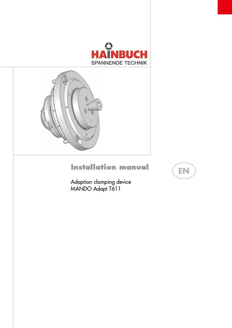
Hainbuch MANDO G211 User manual

Operating instructions
[incl. installation manual]
MANDO G211
EN

MANDO G211
2
Order hotline +49 7144.907-333
Translation of the original operating instructions
Order hotline +4 9 7144.907-333

MANDO G211
Order hotline +49 7144.907-333
3
Contents
1General................................................................................................................7
1.1 Information about this manual.....................................................................7
1.2 Key to symbols............................................................................................7
1.3 Definition of terms.......................................................................................8
1.3.1 Release setting..............................................................................8
1.3.2 Complete clamping reserve...........................................................8
1.4 Limitation of liability.....................................................................................9
1.5 Copyright.....................................................................................................9
1.6 Scope of delivery ........................................................................................9
1.7 Spare parts and accessories.....................................................................10
1.8 Warranty terms .........................................................................................10
2Safety................................................................................................................11
2.1 Responsibility of the operator....................................................................11
2.2 Personnel requirements............................................................................12
2.3 Intended use.............................................................................................13
2.4 Personal protective equipment..................................................................15
2.5 Particular hazards.....................................................................................16
2.6 Other safety instructions ...........................................................................18
2.7 Screws......................................................................................................20
2.8 Functionality..............................................................................................21
2.9 Environmental protection ..........................................................................21
3Technical data...................................................................................................22
3.1 General information...................................................................................22
3.2 Performance values..................................................................................23
3.3 Balancing quality.......................................................................................23
3.4 Speed........................................................................................................24
3.5 Operating conditions.................................................................................24
3.6 Type designation.......................................................................................24
4Layout and function...........................................................................................25
4.1 Overview and brief description..................................................................25
4.2 Accessories required.................................................................................26
4.2.1 Spindle flange..............................................................................26
4.2.2 Drawtube adapter........................................................................26
4.2.3 Segmented clamping bushing .....................................................26
4.2.4 Workpiece end-stop.....................................................................26
4.3 Optional accessories.................................................................................26
4.3.1 hs dock actuating unit..................................................................26
4.3.2 Rotating ms dock actuating unit...................................................26
4.3.3 ms dock stationary actuating unit ................................................27
4.3.4 Adapter kit for a standard spindle flange / hs dock / ms dock......27
4.3.5 mandoteX adapter kit ..................................................................27

MANDO G211
4
Order hotline +49 7144.907-333
5Use and limits of use.........................................................................................28
5.1 Use............................................................................................................28
5.2 Limits of use..............................................................................................28
5.2.1 Nomenclature..............................................................................28
5.2.2 First limit [workpiece length] ........................................................28
5.2.3 Second limit [workpiece mass] ....................................................29
5.2.4 Third limit [clamping length].........................................................29
5.2.5 Fourth limit [forces]......................................................................29
6Transport, packaging, storage...........................................................................31
6.1 Safety, transport, packaging, storage .......................................................31
6.2 Symbols on the packaging........................................................................32
6.3 Transport inspection..................................................................................32
6.4 Unpacking and internal transportation.......................................................33
6.5 Packaging.................................................................................................33
6.6 Storage .....................................................................................................34
6.7 Preservation..............................................................................................34
6.8 Return to storage ......................................................................................34
7Installation.........................................................................................................35
7.1 Installation safety ......................................................................................35
7.2 Preliminary remarks..................................................................................36
7.3 Screw tightening torques...........................................................................37
7.4 Preparation of the machine for installation................................................38
7.5 Installation of the product..........................................................................39
7.5.1 Compatibility check......................................................................39
7.5.2 Preparation of the product...........................................................39
7.5.3 Installation of the product on an actuating unit ............................43
7.5.4 Installation of the drawtube adapter.............................................44
7.5.5 Installation of a spindle flange that cannot be aligned.................45
7.5.6 Installation of a spindle flange that can be aligned ......................47
7.5.7 Installation of the functional unit of an alignable clamping device49
7.5.8 Installation of the functional unit of a non-alignable clamping
device..........................................................................................52
7.6 Installation of the clamping element..........................................................54
7.7 Installation of the changing parts ..............................................................56
7.7.1 Installation of the variant x-times with axial screw connection.....57
7.7.2 Installation of the variant x-times with bayonet axial screw
connection...................................................................................58
7.8 Aligning the clamping device with the test specimen ................................59
8Commissioning..................................................................................................60
8.1 Commissioning safety...............................................................................60
8.2 Checking the total stroke...........................................................................61
8.3 Tests.........................................................................................................62
8.4 Workpiece.................................................................................................63
MANDO G211
Order hotline +49 7144.907-333
5
8.5 Procedure after a collision.........................................................................63
9Activities after end of production .......................................................................64
10 Removal............................................................................................................65
10.1 Safe removal.............................................................................................65
10.2 Preparing the machine for removal...........................................................67
10.3 Removal of the changing parts .................................................................67
10.3.1 Removal of the variant x-times with axial screw connection........68
10.3.2 Removal of the variant x-times with axial screw connection
bayonet........................................................................................69
10.4 Removal of the clamping element.............................................................70
10.5 Removal of the product.............................................................................73
10.5.1 Removal of the product from an actuating unit............................73
10.5.2 Removal of the functional unit .....................................................74
10.5.3 Removal of the spindle flange .....................................................75
10.5.4 Removal of the drawtube adapter................................................76
11 Maintenance......................................................................................................77
11.1 Maintenance safety...................................................................................77
11.2 Maintenance schedule..............................................................................77
11.3 Cleaning....................................................................................................78
11.4 Visual inspection.......................................................................................81
11.5 Lubricating the product..............................................................................81
11.6 Use of lubricants .......................................................................................82
12 Disposal.............................................................................................................83
13 Faults.................................................................................................................84
13.1 Procedure with faults.................................................................................84
13.2 Fault table.................................................................................................85
13.3 Commissioning after a fault has been remedied.......................................86
14 Annex................................................................................................................87
14.1 Contact......................................................................................................87
14.2 Manufacturer certification..........................................................................87

MANDO G211
6
Order hotline +49 7144.907-333
Directory of tables
Table 1: Technical data..............................................................................22
Table 2: Operating conditions ....................................................................24
Table 3: Nomenclature application limits....................................................28
Table 4: Maximum workpiece mass...........................................................29
Table 5: Screw tightening torques, metric control threads..........................38
Table 6: Screw tightening torques for aluminum components....................38
Table 7: Maintenance table........................................................................78
Table 8: Selection of lubricants ..................................................................82
Table 9: Fault table.....................................................................................86

MANDO G211
General
Order hotline +49 7144.907-333
7
1 General
1.1 Information about this manual
This manual enables you to work safely and efficiently with
the product.
This manual is part of the product and must be kept in a lo-
cation directly beside the product that is accessible to the
personnel at all times. The personnel must have read this
manual carefully and understood its contents before starting
any work. The basic requirement for safe work is compliance
with all stipulated safety notices and work-related instruc-
tions in this manual.
If the product is passed onto a third party, this manual must
accompany it.
Illustrations in this manual are there to facilitate a basic un-
derstanding, and may differ from the actual design configu-
ration of the product.
WARNING
Serious injuries caused by individual products or
by inappropriate combinations of them!
Read and pay attention to all operating instruc-
tions for individual products and combinations of
them.
1.2 Key to symbols Safety instructions in this manual are designated by sym-
bols. The safety notices are invoked by signal words that ex-
press the level of hazard involved.
Always comply with safety notices and exercise caution to
avoid accidents, injury to people and damage to materials.
Safety notices
DANGER
… indicates an immediate and hazardous situation
that can lead to death or serious injury if not avoided.
WARNING
… indicates a potentially hazardous situation that can
lead to death or serious injury if not avoided.
CAUTION
… indicates a potentially hazardous situation that can
lead to moderate or slight injuries if not avoided.
NOTE
… indicates a potentially hazardous situation that can
lead to damage to materials if not avoided.

MANDO G211
General
8
Order hotline +49 7144.907-333
Tips and recommenda-
tions
INFORMATION
… highlights useful tips and recommendations as well
as information for efficient and problem-free opera-
tion.
… refers to other documents relating to personal and
general safety.
Warning symbols may appear on the product or its compo-
nents.
Always pay attention to warning symbols, and exercise cau-
tion to avoid accidents, injury to people and damage to ma-
terials.
… warns of stored energy [for example involving springs].
… warns of hand injuries.
… draws attention to the fact that the operating instructions
of the product must be read.
1.3 Definition of terms
1.3.1 Release setting Release setting means that the clamping device is released.
If the clamping device is released, this also releases the
workpiece.
1.3.2 Complete clamping reserve
Complete clamping reserve means that the clamping device
is clamped without a workpiece. The complete stroke has
been used up, which means that the clamping device is
therefore at the limit position for clamping reserve.

MANDO G211
General
Order hotline +49 7144.907-333
9
1.4 Limitation of liability All details and notices in this manual were compiled with due
reference to applicable standards and specifications, state-
of-the-art technology and our many years of expertise and
experience.
The manufacturer accepts no liability for damage arising
from any of the following:
Non-compliance with this manual
Unintended use
Use of untrained personnel
Autonomous conversion work
Technical modifications
Use of non-approved spare parts
Use of non-approved accessories
Installation and use of clamping elements not made by
the manufacturer
Subject to any commitments agreed to in the supplier con-
tract, the General Terms & Conditions of Business and the
delivery terms of the manufacturer and all legislative stipula-
tions valid at the time of conclusion of this contract.
1.5 Copyright This manual is protected by copyright, and are only intended
for internal use.
The dissemination of this manual to third parties, reproduc-
tions in any shape or form - even in part - as well as com-
mercial use and/or communication of their contents are pro-
hibited for anything other than internal use, except with the
written consent of the manufacturer.
Infringements oblige the offending party to pay compensa-
tion. Without restriction on further claims.
1.6 Scope of delivery The scope of delivery of this product includes:
MANDO G211
The operating instructions
Additionally needed and included as optional items in the
scope of delivery:
Spindle flange
Drawtube adapter
Segmented clamping bushing
Workpiece end-stop
if necessary, adapter kit for standard spindle flange

MANDO G211
General
10
Order hotline +49 7144.907-333
1.7 Spare parts and accessories
WARNING
Serious injuries can be caused by incorrect or de-
fective spare parts!
Always use genuine spare parts made by the orig-
inal manufacturer.
WARNING
Serious injuries can be caused by incorrect or de-
fective clamping elements!
Always use genuine clamping elements made by
the original manufacturer.
NOTE
Damage, malfunctions or total failure of the prod-
uct or the machine tool caused by an incorrect or
defective spare parts!
Always use genuine spare parts made by the orig-
inal manufacturer.
NOTE
Damage, malfunctions or total failure of the prod-
uct or the machine tool caused by an incorrect or
defective clamping elements!
Always use genuine clamping elements made by
the original manufacturer.
Spare parts and accessories can be sourced from contract
dealers or directly from the manufacturer [see »Contact«
chapter].
Without exception, wearing parts and components in contact
with the workpiece are not covered by warranty.
1.8 Warranty terms The warranty terms are included in the manufacturer's Gen-
eral Terms & Conditions of Business.

MANDO G211
Safety
Order hotline +49 7144.907-333
11
2 Safety This section provides an overview of all the important safety
aspects for optimum protection of personnel, and for safe
and problem-free operation.
2.1 Responsibility of the operator
The product is used in the industrial sector. The operator of
the product is therefore governed by the provisions of Health
& Safety at Work legislation.
As well as the safety notices in this manual, the area of use
of the product must also comply with locally applicable
safety, accident prevention and environmental protection
specifications as well as those in the manual for the machine
tool.
No modifications must be made to the product. The operator
is wholly and solely responsible for any resultant personal
injury and/or damage to materials.
Excepted from this are changing parts that HAINBUCH ap-
proved explicitly for autonomous machining, but specified
limits must never be exceeded.
DANGER
Serious injuries caused by parts being ejected
centrifugally due to a drop in actuating force / sup-
ply pressure!
On the machine, ensure that the actuating force /
the supply pressure do not drop while the product
is in use.
If no precautions have been taken on the machine
to maintain the actuating force / the supply pres-
sure, it is prohibited to use this product on the ma-
chine.
Pay attention to the operating instructions for the
machine tool.
In particular, note that end-stop requests by the machine tool
must be set on the product involved.
DANGER
Serious injuries caused by parts being ejected
centrifugally after defective setting of the ma-
chine!
Set up the end-stop requests by the machine tool
on the product involved.
On a regular basis, check the end-stop requests
of the machine tool [see »Maintenance schedule«
chapter].
If the limit stops are not reached, the productmust
not be used any more.

MANDO G211
Safety
12
Order hotline +49 7144.907-333
2.2 Personnel requirements
WARNING
Serious injuries caused by incorrect handling of
the product by insufficiently skilled or trained per-
sonnel!
All activities must be performed by skilled staff
from the relevant specialist field.
WARNING
Serious injuries caused by unauthorized presence
of unauthorized personnel in the working area!
Keep unauthorized people away from the working
area.
If in doubt, speak to people and direct them to
leave the working area.
Interrupt work until unauthorized people have left
the working area.
NOTE
Serious damage to materials caused by incorrect
handling of the product by insufficiently skilled or
trained personnel!
All activities must be performed by skilled staff
from the relevant specialist field.
This manual name the following skills sets required for vari-
ous different areas of activity:
Skilled specialist
Skilled specialists, due to their professional training,
knowledge and experience and awareness of applicable pro-
visions, are capable of carrying out the work entrusted to
them and independently to identify and avoid potential haz-
ards.
Hydraulics specialist
Hydraulics specialists are trained in the specific task profile
for which they are employed, and are familiar with the rele-
vant standards and legislative provisions.
Due to their vocational training and experience, hydraulics
specialists can work on hydraulic systems and can inde-
pendently identify and avoid potential hazards.
Pneumatics specialist
Pneumatics specialists are trained in the specific task profile
for which they are employed, and are familiar with the rele-
vant standards and legislative provisions.
Due to their vocational training and experience, pneumatics
specialists can work on pneumatic systems and can inde-
pendently identify and avoid potential hazards.

MANDO G211
Safety
Order hotline +49 7144.907-333
13
Electricians
Electricians are trained in the specific task profile for which
they are employed, and are familiar with the relevant stand-
ards and legislative provisions.
Due to their vocational training and experience, electricians
can work on electrical systems and can independently iden-
tify and avoid potential hazards.
Trainees
Trainees can only work on the machine under the supervi-
sion and direction of staff skilled in the relevant specialist
field.
The only people admitted as personnel are those who can
reasonably be expected to carry out their work to a reliable
standard. People whose response capabilities are impaired,
for example by drugs, alcohol or medication, are prohibited.
For the selection of personnel, pay attention to the stipula-
tions applicable at the place of work governing age and spe-
cific vocational requirements.
2.3 Intended use
The product is only intended for installation in a CE-compli-
ant machine tool with a separating set of guards.
The product is only intended for the type of use described
in this manual [see »Use« chapter]. Furthermore, an ex-
tended form of use can be agreed contractually between
manufacturer and operator.
Only skilled staff from the appropriate specialist fields may
install, operate, maintain and clean the product [see »Per-
sonnel requirements« chapter].
Never exceed the technical values stipulated forthe product
[see »General information« and »Operating conditions«
chapters].
Furthermore, never exceed the limits for use of the product
[see »Limits of use« chapter].
Maintain the product at regular intervals [see »Maintenance
schedule« chapter].
When used for its intended purpose, the operational safety
of the product is assured, subject to compliance with relevant
safety stipulations, to the full extent foreseeable.
Intended use also includes compliance with all stipulations
in this manual.
Any form of use beyond the scope of intended use, or other
forms of use of the product, is considered as misuse, and
can lead to dangerous situations.

MANDO G211
Safety
14
Order hotline +49 7144.907-333
DANGER
Serious injuries caused by misuse of the product!
Only in a CE-compliant machine tool with a sepa-
rating set of guards.
Only use for the type of use indicated [see »Use«
chapter].
Only skilled staff from the appropriate specialist
fields may use the product [see »Personnel re-
quirements« chapter].
Never exceed the technical data indicated on the
product [see »General information« and »Operat-
ing conditions« chapters].
Never exceed the limitsfor use of the product [see
»Limits of use« chapter].
Maintain the product at regular intervals [see
»Maintenance schedule« chapter].
Only use with approved attachments and/or
clamping elements.
DANGER
Serious injuries caused by parts being ejected
centrifugally during commissioning without a
workpiece!
Never rotate the product without a workpiece in-
stalled.
For commissioning, clamp an appropriate work-
piece at every available clamping point.

MANDO G211
Safety
Order hotline +49 7144.907-333
15
NOTE
Damage to materials caused by incorrect use of
the product!
Only in a CE-compliant machine tool with a sepa-
rating set of guards.
Only use for the type of use indicated [see »Use«
chapter].
Only skilled staff from the appropriate specialist
fields may use the product [see »Personnel re-
quirements« chapter].
Never exceed the technical data indicated on the
product [see »General information« and »Operat-
ing conditions« chapters].
Never exceed the limitsfor use of the product [see
»Limits of use« chapter].
Maintain the product at regular intervals [see
»Maintenance schedule« chapter].
Only use with approved attachments and/or
clamping elements.
Claims of all kinds will be rejected that are due to unintended
use.
Here are some examples of unintended use of the product
If workpieces are not clamped properly.
If people fail to observe the safety stipulations when
working on the product, and failing to use additional pro-
tective equipment, for example to machine clamped
workpieces.
If the product is used on machines, workpieces and/or
changing parts for which it is not intended.
2.4 Personal protective equipment
During work, it is essential to wear personal protective equip-
ment to minimize the health hazards.
Always wear the required personal protective equipment
when working on any given job.
Always pay attention to any notices about personal protec-
tive equipment displayed in the working area.
Always wear
When working, always wear the following items:
Workplace clothing
Workplace clothing should be close-fitting, with low tear-re-
sistance, narrow cuffs and no protruding parts. It serves pri-
marily to protect the wearer from coming into contact with
moving machine parts. Do not wear rings, chains or other
jewelry.

MANDO G211
Safety
16
Order hotline +49 7144.907-333
Safety footwear
To protect the wearer from any heavy items that may fall,
and from losing their footing on slippery ground.
Protective goggles
To protect the eyes from projectile parts and liquid
splashes.
Hair net
To protect long hair from getting snagged in rotating parts
on the machine tool.
Additional personal
protective equipment
When carrying out certain work, additional personal protec-
tive equipment is required. Separate reference is made to
this in the individual chapters of this manual. The following
section explains these additional items of personal protec-
tive equipment:
Protective gloves
To protect the hands from friction, chafing, stabbing or
deeper injuries and from contact with hot surfaces.
Hard hat
To protect against falling and projectile parts and materials.
2.5 Particular hazards The following section names residual risks resulting from the
installation of the product in a machine tool. In all cases, the
residual risks detected during a risk assessment of the ma-
chine tool need to be named by the operator.
Pay attention to the safety instructions named here, as well
as the warning notices in other chapters of these operating
instructions to reduce the risk of health hazards and to pre-
vent dangerous situations.

MANDO G211
Safety
Order hotline +49 7144.907-333
17
Moving parts
WARNING
Serious injuries caused by touching rotating
and/or moving parts!
Do not open guards while the system is operating.
During operation, do not reach for rotating and/or
moving parts.
Pay attention to the gap dimensions of moving
parts.
Before opening the guards, ensure that none of
the parts are moving any more.
Stroke
WARNING
Serious crushing injuries caused by the stroke of
the product!
Never reach into an area where moving parts are
operating.
Prevent accidental initiation of the clamping pro-
cess [for example due to an installation error with
the power supply or a programming error].
Insufficient workpiece
clamping
DANGER
Serious injuries caused by parts being ejected
centrifugally if level of workpiece clamping is in-
sufficient!
Workpiece blanks must not be outside the clamp-
ing width diameter.
Clamping of the workpiece must not be outside
the defined limits [see »Limits of use« chapter].
Do not exceed the maximum performance values
[see »General information« chapter].
Insufficient workpiece
clamping
WARNING
Serious injuries caused by breakage of individual
components of the product when actuating force
is too high!
Check actuating force on a regular basis and ad-
just if necessary.

MANDO G211
Safety
18
Order hotline +49 7144.907-333
Sharp-edged parts
WARNING
Serious cut injuries caused by sharp-edged parts
and burrs!
All installation of individual parts must be per-
formed by skilled staff from the relevant specialist
field.
Also wear the following items of personal protec-
tive equipment, in addition to the basic equip-
ment:
2.6 Other safety instructions
DANGER
Serious injuries caused by workpieces being
ejected centrifugally when clamping unit is re-
leased while still rotating!
Never release the clamping of the workpiece
while it is still rotating.
DANGER
Serious injuries caused by projectile workpieces!
To assist clamping of the workpiece with long
clamping devices, always use a tailstock / back
rest or a brace.
WARNING
Serious injuries caused by media escaping under
high pressure due to missing / damaged seal ele-
ments!
Ensure that all sealing elements for the media
ports are present and are undamaged.
Lubricate the sealing elements before every in-
stallation and at every maintenance operation.

MANDO G211
Safety
Order hotline +49 7144.907-333
19
WARNING
Serious head injuries caused by bending into the
working area of the machine!
Only ever bend into the working area of the ma-
chine if there are no cutting tools or sharp objects
in it, or if these are covered.
Never move body partsunder parts in the working
area of the machine with the potential to drop
down.
WARNING
Serious injuries caused by snagging body parts
on the rotating machine spindle!
Never reach into the product while the machine
spindle is still rotating.
Before working on the product, ensure that the
machine spindle is unable to start up.
WARNING
Serious injuries caused by reaching into slots and
bores!
Never reach into slots or bores.
WARNING
Serious injuries caused by workpieces dropping
or the clamping unit getting released!
Only unclamp the workpiece if it is protected
against falling.
WARNING
Serious injuries caused by the use of damaged
products or by their components and accesso-
ries!
Check products or their components and acces-
sories on a regular basis for visible signs of dam-
age [see »Inspections« and »Cleaning« chap-
ters].
Use of damaged products, their damaged compo-
nents and/or their damaged accessories is pro-
hibited.
Report damage to the operator immediately.
Damaged components / accessories must be re-
placed with genuine spare parts / accessories
made by the manufacturer.

MANDO G211
Safety
20
Order hotline +49 7144.907-333
CAUTION
Cut injuries caused by sharp edges and burrs re-
sulting from wear and/or repeated rework!
Remove sharp edges and burrs.
If necessary, replace worn components with gen-
uine parts made by the manufacturer.
NOTE
Serious damage to materials / the machine tool /
the product caused by workpieces being ejected
centrifugally if clamping is released while they are
still rotating!
Never release the clamping of the workpiece
while it is still rotating.
NOTE
Damage to materials caused by untightening the
wrong screws!
Do not open the screws secured with sealing lac-
quer.
2.7 Screws
WARNING
Serious injuries caused by radially installed
screws being ejected centrifugally if installed in-
correctly / poor handling!
Do not open the screws secured with sealing lac-
quer.
Screws and threaded pins fitted radially to the
product that were bonded with adhesive need to
be secured again using a standard, medium-
strength screw adhesive and tightened to the
specified tightening torque [see nomenclature or
the »Screw tightening torques« chapter]. Before
reinstallation, clean and degrease the screw and
internal thread.
Radially mounted screws and threaded pins that
were not bonded with sealing lacquer or an adhe-
sive need to tightened back down to the specified
tightening torque [see nomenclature or the
»Screw tightening torques« chapter].
If in doubt, contact the manufacturer immediately
to determine how best to proceed.
Table of contents
Other Hainbuch Adapter manuals

Hainbuch
Hainbuch MANDO T211 User manual

Hainbuch
Hainbuch T812 User manual

Hainbuch
Hainbuch centroteX S User manual

Hainbuch
Hainbuch centroteX M User manual

Hainbuch
Hainbuch HYDROK User manual

Hainbuch
Hainbuch T812 User manual

Hainbuch
Hainbuch MANDO Adapt T611 User manual

Hainbuch
Hainbuch mandoteX User manual

Hainbuch
Hainbuch MANOK Plus User manual

Hainbuch
Hainbuch mandoteX User manual
Popular Adapter manuals by other brands

Siemens
Siemens DRAE3 installation instructions

PI Manufacturing
PI Manufacturing ANT-S300CPE installation manual

Comtrend Corporation
Comtrend Corporation GCA-7000 Quick installation guide

iLive
iLive IAB13 user manual

TP-Link
TP-Link Archer T4UHP Quick installation guide

Christie
Christie M Series instruction sheet